|

|
Forum Index : Electronics : Amberís diy transformer
| Author | Message | ||||
| BenandAmber Guru Joined: 16/02/2019 Location: United StatesPosts: 961 |
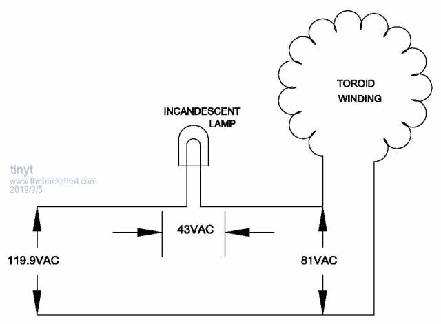
119.9 main wall outlet 81 volts after light bulb 43 across the light bulb I'm trying to figure out volts per turn Ben can't help me because he don't know either Me and him both need to be able to figure this stuff out for ourselves we need a very simple way of figuring this out give a guy fish eats for one day teach him how to fish type deal Are these Transformers for inverters supost to be a dead short when not using the bulb We did at one time have the equation for finding how many turns we (we had that technology but we destroyed it and now it would be too big of a process to get it back) NASA joke but anyway we did not understand it but used it to wind the secondary on this Transformer when ben saw it was a dead short he thought we done something wrong and it sat in shed for a year or so now we can't find netbook with directions on finding volts per turn we are thinking all inverter Transformers acts like a short when secondary is hooked up to Mains voltage if anyone can explain this to us we would really appreciate it we could definitely follow a recipe if someone had a simple one thanks yall   be warned i am good parrot but Dumber than a box of rocks |
||||
| Pete Locke Senior Member Joined: 26/06/2013 Location: New ZealandPosts: 181 |
Well if it was me, I'd wind ten turns of whatever you have on hand onto the transformer. Hit it with the input power and measure your voltage on the new extra winding. That will give you a turns per volt number. Might be missing something in your original query, but when winding new secondary's on old transformers back in the hobby days, that worked well. Cheers Pete'. |
||||
| Clockmanfr Guru Joined: 23/10/2015 Location: FrancePosts: 429 |
Hi, Here is my roughed out chapter 4 on the toroid of the second edition, 'How to Make a 6kW OzInverter'. All the information you require, and the calculations for volt per turn. I also show the testing procedure of the toroids. 2019-03-04_184655_Ch42ndEdtOzInverterToroid1.pdf 2019-03-04_184749_Chpt42ndEdOzinverterToroid2.pdf 2019-03-04_184816_Ch42ndEdtOzInverterToroid3.pdf 2019-03-04_184837_Ch42ndEdyOzInverterToroid4.pdf As regards USA 120vac, we tap the secondary on half its turns for a 240vac winding, so the tap becomes a floating neutral. We still use the OzControl board as it still uses the 240vac regulation, but we alter the HZ output for 60HZ. Everything is possible, just give me time. 3 HughP's 3.7m Wind T's (14 years). 5kW PV on 3 Trackers, (10 yrs). 21kW PV AC coupled SH GTI's. OzInverter created Grid. 1300ah 48v. |
||||
| tinyt Guru Joined: 12/11/2017 Location: United StatesPosts: 438 |
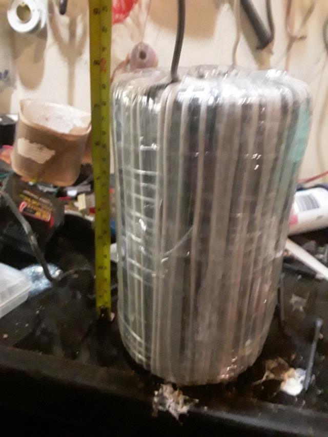
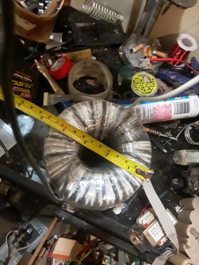
The way I understand the above, the connection looks like this. Lamp wattage is not given. I don't know which winding is connected. It should be the one with the higher number of turns for this test.  And there is no load on the other winding. For an efficient transformer, the voltage across the lamp should be low and almost all of the 120vac should be across the transformer winding being tested. Based on the pictures, the toroid is roughly 4 inches OD and 2 inches ID and the toroid core stack is 7 inches (177.8mm). The toroid core ring width is roughly (4-2)/2 = 1 inch (25.4mm). So the toroid core cross section is 25.4 x 177.8 = 4516mm sq.(roughly) Using the magic number of 2800 (for 50Hz) in Clockman's guide, the volts/turn(?) ratio is 4516/2800 = 1.6128. So, for the 120vac winding, the number of turns is 75 (for 50Hz). I think we can just use the ratio 5/6 to get 75*5/6 = 63 turns for 60 Hz. Looking at the pictures, I assume the white thing is the wire winding with more turns and the black thing has less turns. I am assuming that in the test, the white winding is the one connected. I don't know how many layers of white wires there are, assuming there is only one layer, I counted roughly 50 turns. I think you will need more turns. And since there is a big space inside the toroid hole, I will put more turns than the rough calculation above. If you post the number of turns for each winding that you have now maybe we can get a clearer picture. |
||||
| LadyN Guru Joined: 26/01/2019 Location: United StatesPosts: 408 |
The transformer is an inductor and hence to DC it looks like almost a short. Most multimeters inject a constant current into the load and check the voltage drop to calculate the resistance. What is the multimeter you are using to measure the windings? You really need an oscilloscope. In DC it looks like almost a short and to AC it only shorts when the other winding is shorted out as well. You really need to inject or feed an AC signal into the winding and put an oscilloscope across it. You are going to use the transformer in the AC domain so any DC domain analysis is not going to be very helpful. Do you have an oscilloscope? |
||||
| BenandAmber Guru Joined: 16/02/2019 Location: United StatesPosts: 961 |
Thank you tinyt the white and black wire is the 120 volt 60 hertz wanding she did it about a year ago and lost her Notepad that she had everything wrote down in but I'm thinking she put around 114 turns on it she did the calculations and added a few more turns she was trying to figure out how many windings for the low side windings she figured it out few nights ago I helped her wind it I know she had me help her wind 22 turns I can't remember how many volts per turn and all that though I think you got a really close especially for just looking at a picture thanks again for all your help be warned i am good parrot but Dumber than a box of rocks |
||||
| BenandAmber Guru Joined: 16/02/2019 Location: United StatesPosts: 961 |
And about the Transformer acting like a short I'm talking about on AC it will trip the surge protector breaker if I don't put a light bulb in series this is with a professionally wound Transformer out of a inverter also I'm trying to wrap my head around this is it the end Rush current or if where inverter Transformers have fewer turns are they not meant to be used in this way I am talking about no shorted out secondary it would be secondary in this case because the one with the most turns is the one I'm am hooking up to the surge protector so I guess my question is do all inverter Transformers act like a short without a light bulb in series when you hook the side with the most turns up to ac voltage because it seems that way to me unless I'm doing something wrong in the case of Amber's Transformer only the higher turn side had been wound and we was trying to figure out how many terms for the Least turn side be warned i am good parrot but Dumber than a box of rocks |
||||
| tinyt Guru Joined: 12/11/2017 Location: United StatesPosts: 438 |
So based on the picture and your description above, you have two separate windings in series. One winding is black wire and the other is white wire and the total of the two is 114 turns. But I don't know if they are split equally ( white=57 turns, black=57 turns). And there are no other windings. Assuming there are no shorted turns, the only thing I can think of based on the above assumption is the phasing of the two windings. Try reversing the series connection of one of the colored winding with the other colored winding and retest. Example: White wire: SW(start end) - winding - FW(finish end) Black wire: SB(start end) - winding - FB(finish end) Initial connection that is tripping the circuit breaker (phasing unknown): SW(start end) - winding - FW(finish end) *series* SB(start end) - winding - FB(finish end) New connection to test(change phasing): SW(start end) - winding - FW(finish end) *series* FB(finish end) - winding - SB(start end) |
||||
| BenandAmber Guru Joined: 16/02/2019 Location: United StatesPosts: 961 |
Amber didn't have enough of the black wire so she had me solder the black and the white wire together it's the exact same gauge it's 10 2 electrical outside burial wire both wires came from this wire the outside sheath was cut inside wires removed they were put end to end and soldered together then heat shrink was added it was wound in a single wind in out and around it was so long it was about impossible that's what she uses me for to chase wire while she Loops it through she puts her feet on the Transformer and pulls like hell lol probably a much better way to do this it wouldn't fit on a bobbin the least winding side is number three enameled wire from a giant e style Transformer now the test the wall outlet voltage during test was 120.9 Voltage after light bulb which is an old microwave light bulb is 81.4 Voltage across light bulb is 43.8 Voltage on the least turn side was 25.2 This test was done with light bulb only I didn't have a switch and was just going to jump across the light bulb and it made a spark so I chickened out she was going for 32 volts on the least turn side for the little 4 mosfet China board be warned i am good parrot but Dumber than a box of rocks |
||||
| LadyN Guru Joined: 26/01/2019 Location: United StatesPosts: 408 |
Ben I think if you have to patch wires in a run when you run out of wire, you have to take that run out of the winding to outside, solder new wire to it and run the new wire back in instead of connecting the two wires inline, if that is what you did. I have not spent a lot of time learning about transformers but: 1. Nothing beats practical experience. so I will love to see how this transformer both of you built works out 2. You will get more feedback from others once you have something working and you find issues in it to make it better I will start to learn about transformers though. Thanks to your very very generous gift, I now have the toroids that I badly needed and now I have the cores to wind around! I am excited about this thread! |
||||
| BenandAmber Guru Joined: 16/02/2019 Location: United StatesPosts: 961 |
I just went out to the shed and grab a switch the last time I ran this test it was real cold out and I was too lazy to go out to the building and get a switch I just went outside goddess switch put it across the light bulb Amber's Transformer output with full Voltage was 38 volts it's supposed to be 32 so I think she might have over shot a little bit but my Mains voltage tonight it's pretty high it's a hundred and twenty two she is asleep I don't remember how many volts per turn it was so I'll have to wait on her see how many turns she needs to take back off be warned i am good parrot but Dumber than a box of rocks |
||||
| ltopower Regular Member Joined: 08/03/2019 Location: United KingdomPosts: 64 |
WIth : core size OD 101.6mm ID 50.8mm, HT 177.8mm core area 4516cm2 Flux density : 0.875 T @ 60Hz Primary : 114 turns (1.053V/turn) - 120V input Secondary : 22 Turns - 23.16V output You need closer to 30 turns for 32V I think... 1st edit.. |
||||
| BenandAmber Guru Joined: 16/02/2019 Location: United StatesPosts: 961 |
I'd say you're right I don't want to touch it without her though she might get a little mad happy wife happy life be warned i am good parrot but Dumber than a box of rocks |
||||
| BenandAmber Guru Joined: 16/02/2019 Location: United StatesPosts: 961 |
The big one done okay with the switch 2 they had me worried for a little bit without a switch I just touched the two light bulb wires together last time I tested and it gave a pretty good spark so I left it alone I was awaiting an opinion on it from another person on this form but I guess I answered my own question this guy seems to give me a little while to try to figure it out by myself I think it's his way of trying to get me to figure things out myself which is very good and I appreciate it be warned i am good parrot but Dumber than a box of rocks |
||||