
|

|
Forum Index : Electronics : Inverter PCB’s
| Author | Message | ||||
oztules Guru Joined: 26/07/2007 Location: AustraliaPosts: 1686 |
Mad... your the man with the GTI backfeed. Recently put in 6kw of aerosharp backfeed for a bloke over here. Last two months worked perfectly, and I expect will in future. I shorted the inputs together, and no sign of a problem.... I expect this would have solved your problems with isolated inputs as well. .........oztules Village idiot...or... just another hack out of his depth |
||||
Madness Guru Joined: 08/10/2011 Location: AustraliaPosts: 2498 |
Gidday Oz, good to hear from you. Originally I had the inputs together like you described into the one inverter but every time it started regulating at least one MOSFET shorted, then no more regulation. It stopped shorting out when I separated the Drains for each channel of the MPPT. This was how I had the original PCB and it worked fine (and still does) it was only by going back to this one I discovered the fault. I have no idea why but since separating the drains on the PCB (same as the one I sent you) it has been magic. As to why I have no idea! The same GTI is now running with 7KW of panels and open circuit voltage >500V. There are only 10 types of people in the world: those who understand binary, and those who don't. |
||||
oztules Guru Joined: 26/07/2007 Location: AustraliaPosts: 1686 |
I do mean short the inputs to the inverters, so there is a single output from the controller. That way, who cares what the mppt's think, they share a common source/input. They can fight over it, but the controller does not see this competition, it only see's the aggregate draw..... it shouldn't/can't interfere with the control system then, only have varying drain on it. What this means for the hf inverters I don't know, but for the aero sharps it works fine. I do know it messes with the mppt a bit, as the two inverters give differing outputs all the time for the common rail inputs... and I am not sure why. ( when yours is not "controlling", that will mean a common rail input as well I guess.) ......oztules Village idiot...or... just another hack out of his depth |
||||
Madness Guru Joined: 08/10/2011 Location: AustraliaPosts: 2498 |
They where shorted all connected to the same common track on the regulator PCB. What I know is once separated it works perfectly so I am leaving it alone. There are only 10 types of people in the world: those who understand binary, and those who don't. |
||||
renewableMark Guru Joined: 09/12/2017 Location: AustraliaPosts: 1678 |
Mad, I'll update the shopping cart 2 inverter control boards 2 inverter power boards 1x GTI control board 4x cooling boards. Cheers Mark Cheers Caveman Mark Off grid eastern Melb |
||||
Madness Guru Joined: 08/10/2011 Location: AustraliaPosts: 2498 |
I have the updated control board about 75% completed once I get that sorted out I will post details then we can start looking at firming up who wants what exactly. There are only 10 types of people in the world: those who understand binary, and those who don't. |
||||
oztules Guru Joined: 26/07/2007 Location: AustraliaPosts: 1686 |
Mad, if it works... it works... stick with what works for you. ......oztules Village idiot...or... just another hack out of his depth |
||||
| gpalterpower Senior Member Joined: 19/07/2009 Location: AustraliaPosts: 175 |
Madness... Think I will upgrade the order as well. I feel another project coming on!  1 x inverter control board 1 x inverter power board 2 x GTI control boards 2 x cooling boards. So how many you up now? seems to have snowballed somewhat! When and how would you like to be paid? Marcus if it aint broke dont fix it!! |
||||
Madness Guru Joined: 08/10/2011 Location: AustraliaPosts: 2498 |
I have completed the new version of the control board and have done a preliminary check but would appreciate if anyone out there interested could check these for me also please. The circuit should be identical to Oztules latest version except for the Arduino Nano that I have added to for Low voltage shut down. I have made more use of the top side than Oztules version as he did this originally with the intention of DIY single sided PCBs. 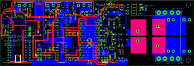 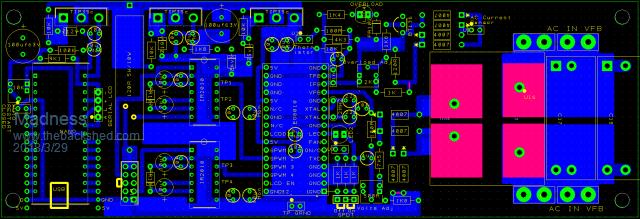 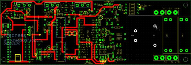 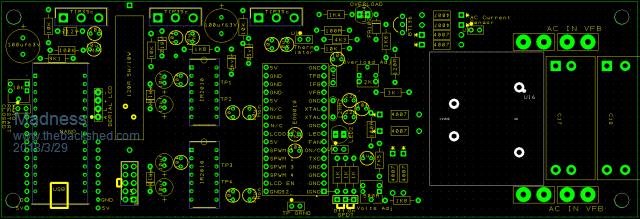 There are only 10 types of people in the world: those who understand binary, and those who don't. |
||||
Madness Guru Joined: 08/10/2011 Location: AustraliaPosts: 2498 |
I have made PDFs but they are still not super clear I can email much better images to anyone who would like them. 2018-03-29_162306_All.pdf 2018-03-29_162334_Bot.pdf 2018-03-29_162403_Top.pdf 2018-03-29_162424_Silk.pdf There are only 10 types of people in the world: those who understand binary, and those who don't. |
||||
| Tinker Guru Joined: 07/11/2007 Location: AustraliaPosts: 1904 |
Mad, The way I check PCB artwork is drawing the complete schematic (I know you don't like doing that  ) and then colour trace each connection as I check it on the board. ) and then colour trace each connection as I check it on the board.With that neat feature of track highlighting of the PCB software you use that task should be easy. You will find having a neat schematic pays off many times over in the case you have to trace a problem down the track  . .Another thing I found useful is putting the project aside a few days before checking it, surprisingly often I had realised that I'd forgotten to include something on the board. Hindsight is quite useful at times. Klaus |
||||
Madness Guru Joined: 08/10/2011 Location: AustraliaPosts: 2498 |
Yes putting something down and walking away for a while can be the quickest and easiest way to sort out something complicated. I used to try drawing circuits with the software but I found it took 4 times longer to get the job finished. Though if it was a really big circuit I am sure it would be hard to do it without a circuit. Stuff like this though you can break into bite-size pieces. I was hoping though that someone wanting boards might contribute a little, I am not making a profit out of this. There are only 10 types of people in the world: those who understand binary, and those who don't. |
||||
| Tinker Guru Joined: 07/11/2007 Location: AustraliaPosts: 1904 |
That sounds a good reason but that person would require the full knowledge of exactly what the board does. And you have introduced new parts with that low voltage sensing, nobody but you would know as yet what this involved. Now, I do not require any boards but I could not check your artwork without that knowledge. And that means a full schematic for me. Its actually not that difficult to draw one if using one of the free programs. Much easier than laying out the PCB, imo. Does not take long either once one has worked out the basics of the program. Klaus |
||||
| tinyt Guru Joined: 12/11/2017 Location: United StatesPosts: 438 |
Some comments from the .png pictures: Are the 2 capacitors under the EGS8010 adapter pcb low profile and will not interfere with the bottom of the adapter pcb? There seems to be a 4-pin serial LCD interface. If you are using I2C, please check the signal pin numbers of the I2C coming from the nano. From the pdf, looks like mounting holes are spaced about 2.8" (71mm) and 9.5" (241mm). Maybe add mounting hole in the middle of the 241mm so that the PCB will not flex too much when inserting/removing the adapter pcb. Too busy at work right now, if I have extra time I will look at them some more later. |
||||
Madness Guru Joined: 08/10/2011 Location: AustraliaPosts: 2498 |
Thanks Tiny well spotted the Serial LCD was incorrect. I have added a hole for support next to the EG8010, also added a connector for the LCD for the EG8010, I know Oz thinks it is pointless but it is there if you want to use it. The 2 Monolithic caps under the EG8010 have plenty of clearance so no problem there. 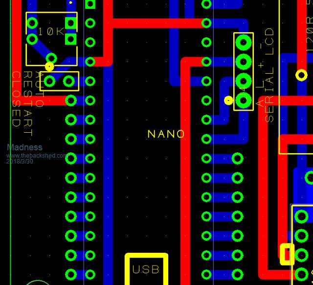 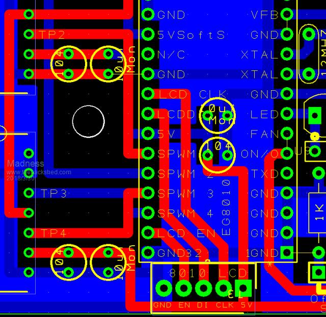 There are only 10 types of people in the world: those who understand binary, and those who don't. |
||||
Madness Guru Joined: 08/10/2011 Location: AustraliaPosts: 2498 |
Just made some changes to the Nano section of the Inverter Control PCB, re waired the voltage input and adjustment and added a playground for future experiments with the Arduino. 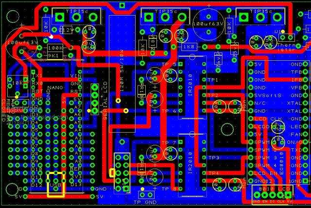 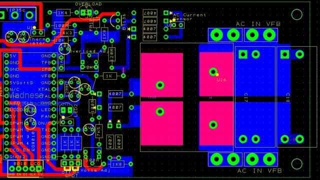 There are only 10 types of people in the world: those who understand binary, and those who don't. |
||||
renewableMark Guru Joined: 09/12/2017 Location: AustraliaPosts: 1678 |
Thanks for your efforts Madness, I know you would like some input, however as you know I couldn't possibly be of any help. But I will say thanks for putting your hand up and helping us all with these custom boards. Cheers Caveman Mark Off grid eastern Melb |
||||
| noneyabussiness Guru Joined: 31/07/2017 Location: AustraliaPosts: 513 |
compatible LCD This is a compatible lcd to the standard eg8010 chips.. quite large and easy to read, if anyone interested. I have tested and they work. I think it works !! |
||||
Madness Guru Joined: 08/10/2011 Location: AustraliaPosts: 2498 |
Mark all it needs is another pair of eyes to compare the PCB with Oztules. There is the left-hand side that is new but the rest is the same excluding the LCD connector. Sometimes there can be a mistake but no matter how many times you look at it you don't see it where to someone else it sticks out like dogs balls. There are only 10 types of people in the world: those who understand binary, and those who don't. |
||||
oztules Guru Joined: 26/07/2007 Location: AustraliaPosts: 1686 |
If A7 for input, D2 for output to temp, then looks good to go to me. ......oztules Village idiot...or... just another hack out of his depth |
||||