|

|
Forum Index : Electronics : A newbie ozinverter build
| Author | Message | ||||
| tinyt Guru Joined: 12/11/2017 Location: United StatesPosts: 438 |
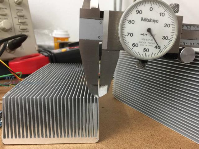
The four dust catchers came. The flimsy fins are only 1mm thick, the base is about 4.5mm thick.  I guess I have to design the pcb around them. I still have to figure out how to bolt them thru the pcb. |
||||
Madness Guru Joined: 08/10/2011 Location: AustraliaPosts: 2498 |
They may work fine as they are, The heatsinks we are using off the old grid tie inverters have thicker fins but a lot less of them also. There is no need to bolt them through the PCB. There are only 10 types of people in the world: those who understand binary, and those who don't. |
||||
| johnmc Senior Member Joined: 21/01/2011 Location: AustraliaPosts: 282 |
Good Day tinyt To tap the thread in thin aluminium use flute less taps as the do not cut the thread but extrude or roll the thread eg 3mm thread would use a 2.65 drilled hole size for thick material . But with thin material and a little trial and error you can reduce the hole size a little, this makes a stronger thread also there is no thread cutting swarf. NOTE you must dip the tap end into light oil before each tapping , this stops the tap galling and breaking. cheers john johnmc |
||||
| tinyt Guru Joined: 12/11/2017 Location: United StatesPosts: 438 |
I learn something new today. Thank you very much johnmc. |
||||
| Tinker Guru Joined: 07/11/2007 Location: AustraliaPosts: 1904 |
And, if you are tapping the thicker bottom, locate your holes so they fall in *between* the fins. Drilling a hole through the base where it breaks through halfway into a fin is a sure recipe to break the drill bit - and tap later. Klaus |
||||
| Tinker Guru Joined: 07/11/2007 Location: AustraliaPosts: 1904 |
Looking at your picture again I see the edge of the base is rounded. If this was my heat sink I would cut the first fin away on one side (along the length of the heatsink). That leaves a square 4.5mm thick base edge that could be tapped with the American gauge equivalent of M3. A few well spaced holes there should suffice to attach the heat sink to the PCB. Then the heat sink base underside is free to accept the Mosfets. This is how I fitted the heat sink to my inverter power board. But I had the luxury of a 10mm thick base and used M4 screws to attach the PCB. If you use the heat sink as a conductor (and you ought to) then you need more attachment screws to provide a good contact to the PCB foil. I used screws spaced 25mm apart (1 inch). Klaus |
||||
| Boppa Guru Joined: 08/11/2016 Location: AustraliaPosts: 814 |
We found that more fins (even though they were thinner), actually had a higher heat transference to atmosphere (more surface area). Also its best if they can be mounted with the fins running vertically, with the heat sources at the bottom- this all aids in natural convection currents aiding heat transfer to the air by allowing maximum air flow past the fins (this was in industrial gear that couldnt be fan assisted due to the area) Even with fans its best to aid the natural airflow rather than try and fight it with the fans (the number of computer cases I have seen set up so they are sucking cold air in the top and trying to force it down the case and out the bottom....) |
||||
| tinyt Guru Joined: 12/11/2017 Location: United StatesPosts: 438 |
Thanks Klaus, I will certainly do this for the mosfets and power conductors. The base is not rounded, that corner probably got banged up during shipment (China Post in plastic bubble wrap, not in a carton box). So I won't need to cut the edge fin. I will try to drill and tap the edge for 1/8 inch screws (~3mm). I don't have an end mill, I only have a clunky drill press, so it will be scribed lines, a simple fence setup on the drill press table, eye-balls and lots of prayers. I might also try one or two fluteless tapped holes thru several fines close to the opposite edge of the base to help keep it vertical to the pcb surface, Maybe I'll just use self-tapping screws and make sure there are no debris left. Thanks. |
||||
| tinyt Guru Joined: 12/11/2017 Location: United StatesPosts: 438 |
Yes, I will do this when I mount the assembly. Thanks. |
||||
| Tinker Guru Joined: 07/11/2007 Location: AustraliaPosts: 1904 |
Or, you could screw a piece of alu angle against the fin ends to work as another 'leg'. A carefully dimensioned self tapper screw could bite in the space between the fins and lock that 'leg' in place. Klaus |
||||
| tinyt Guru Joined: 12/11/2017 Location: United StatesPosts: 438 |
That is a good idea I never thought of it. Will be worth the extra PCB surface it will need. Thanks. |
||||
| tinyt Guru Joined: 12/11/2017 Location: United StatesPosts: 438 |
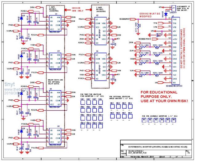
Revised the schematic, more tasks for the nano. Also added the IR2010 that nickskethisniks found as an alternate. Time to layout the PCB and create the gerbers. I will be using this schematic. 2018-03-07_003724_Experimental_Inverter_P2.pdf |
||||
| Warpspeed Guru Joined: 09/08/2007 Location: AustraliaPosts: 4406 |
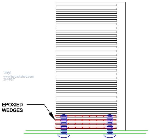
Those fins do look awfully thin to tap. How about finding a suitably thick piece of steel to wedge (or epoxy) between the fins, and then tap the hole through three thicknesses of material. That should be super strong. Cheers, Tony. |
||||
| tinyt Guru Joined: 12/11/2017 Location: United StatesPosts: 438 |
Hi Warpspeed, I like your idea. I don't have to drill/tap thru the thin base also. I think I need to do this only at the opposite ends of the heat sink and not the entire length. Thank you very much.  |
||||
| Tinker Guru Joined: 07/11/2007 Location: AustraliaPosts: 1904 |
It looks awfully complicated  and seems to have a much bigger parts count than my inverter boards have. and seems to have a much bigger parts count than my inverter boards have.But you are having fun which is the most important ingredient when experimenting with these things. I see you are using the EGS002 board. I started my experiments using that board, it works but the board is fragile electrically. It will certainly self destruct if one of your Mosfets blows. A good idea is to order several of the boards, they are not very expensive. Klaus |
||||
| Warpspeed Guru Joined: 09/08/2007 Location: AustraliaPosts: 4406 |
The EGS002 board makes an excellent isolated PWM driver to feed into some really heavy grunt gate driver chips. Its also true that when a mosfet finally goes to mosfet heaven, it often also takes out whatever was driving it. If it kills several your EGS002 boards, as it probably will, that can be a sad loss. But if there is a socket mounted gate driver chip placed between the EGS002 and the mosfet, its only a single driver chip that needs replacing. A heavy duty non inverting gate driver is also far preferable to the wimpy IR isolated gate drivers that are really only designed (and capable of) driving individual smaller sized mosfets. If you are trying to dive several really large mosfets in parallel at a fairly fast switching rate, the EGS002 by itself is just not up to the job. Cheers, Tony. |
||||
| johnmc Senior Member Joined: 21/01/2011 Location: AustraliaPosts: 282 |
Good day Warpspeed, are you suggesting boost drivers such as Tip41\42C that madness and Tinker are using, or what other type of drivers, do you suggest. cheers john johnmc |
||||
| Warpspeed Guru Joined: 09/08/2007 Location: AustraliaPosts: 4406 |
The TIP41/42 drivers will work fine, but if they blow up it requires some resoldering to fix it. I personally prefer TC4452 gate driver chips which will have superior performance (faster and a lot more drive current) and if the driver chip spits the dummy its a simple plug in replacement into an IC socket. Also if the driver chip is unplugged you can test the gate of the big fet with a multimeter without having to remove the fet to do it. Cheers, Tony. |
||||
Madness Guru Joined: 08/10/2011 Location: AustraliaPosts: 2498 |
My Totem pole driver transistors have never failed, I have had a few failures in recent times but that was due to an issue with the DIY regulator on my grid tie inverter. With the appropriate DC breaker when the MOSFETs failed nothing was damaged in the drive circuit or the PCB itself. Even the MOSFETs did not explode, just a tripping of the breaker and shorted FETs. I have fixed the GTI regulator shorting problem and it has run nicely ever since. Soon I will be adding a second GTI to my setup with another 6KW of panels, this will also include a limit of 5KW on the power backfed via the inverter. The GTIs will be able to make the 5KW plus any AC loads, my main reason for adding this is for very cloudy weather. If a Totem pole did fail it would be a couple minutes to snip them off remove each leg and put new ones in, you have to do that with the MOSFETs anyway. Or you could put all of them in with screw terminals as I have seen Warp do elsewhere. There are only 10 types of people in the world: those who understand binary, and those who don't. |
||||
| tinyt Guru Joined: 12/11/2017 Location: United StatesPosts: 438 |
The Mosfets are driven by socketed chips. The choice is IRS2186 or IR2010PBF. There are resistor voltage dividers between these driver chips and the EGS002. I am hoping that the EGS002 is sufficiently isolated. But I will find out during testing which will be much later. Here is latest schematic of the driver section.  I am still placing components in the lay out the PCB, my head is hurting now. |
||||