
|

|
Forum Index : Electronics : China inverter boards
| Author | Message | ||||
| BenandAmber Guru Joined: 16/02/2019 Location: United StatesPosts: 961 |
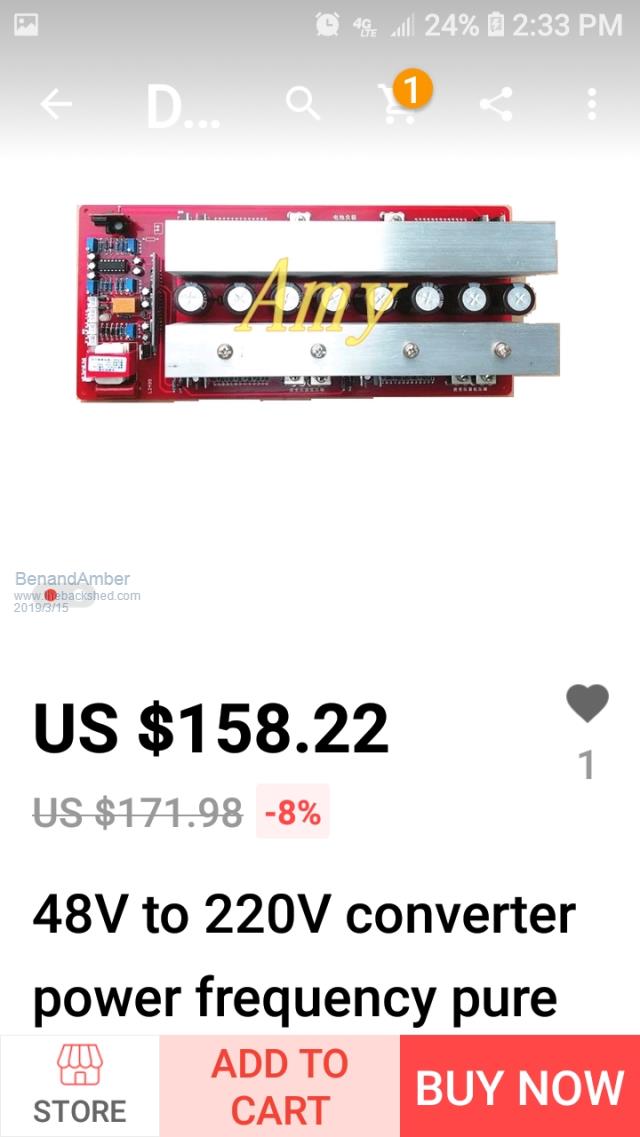  This is the board that we ordered it has the little Transformer on it we really appreciate your help without you we wouldn't have had the confidence to do this you have impacted our life in a positive way we hope one day we'll be able to return the favor be warned i am good parrot but Dumber than a box of rocks |
||||
| poida Guru Joined: 02/02/2017 Location: AustraliaPosts: 1419 |
I am not using an isolation transformer in both of my inverters. This means 240V AC is lead back onto the board, where it gets rectified by a diode bridge, then the voltage is divided down to something reasonable (maybe 10V) and then it's smoothed and divided again down to 3V for Vfb. Oztules has described he had problems with this setup. His inverter was not as stable running as he wanted, until he placed an isolation transformer in the Vfb path. The isolation transformer does that, it removes any DC components that might upset the relationship between Vfb as measured at the EG8010 pin, and various return paths form the loads placed on the inverter output. In my particular situation, the loads and the wiring I have done seem to not produce these DC offsets that upset the inverter's AC output voltage control. With hindsight I would spend a little more if needed and buy inverter boards that have onboard isolation transformers. For better safety (no 240V on the inverter board now) and for better regulation. wronger than a phone book full of wrong phone numbers |
||||
| BenandAmber Guru Joined: 16/02/2019 Location: United StatesPosts: 961 |
I'm not real sure how this board works I think the output of the big Transformer goes back into the board it will be 120 volt instead of 240 volt I might have to change something or this might just be the wrong way to do this I am open to suggestions i really appreciate all the help you have gave me so far I have to change something anyway because it's a 240volt input back into the board and I will be feeding 120 to it I have to change this little Transformer out with one that's 120 volt or I heard that I might be able to get by with changing a few resistor values I'm not sure I'm sure you and others on here know a lot more about it than I do I was hoping for you and or others would chime in I have been trying to find a systemic for this board have had no luck it may not exist And thanks again me and my family appreciate all your help and wish peace happiness and good health to you always be warned i am good parrot but Dumber than a box of rocks |
||||
| BenandAmber Guru Joined: 16/02/2019 Location: United StatesPosts: 961 |
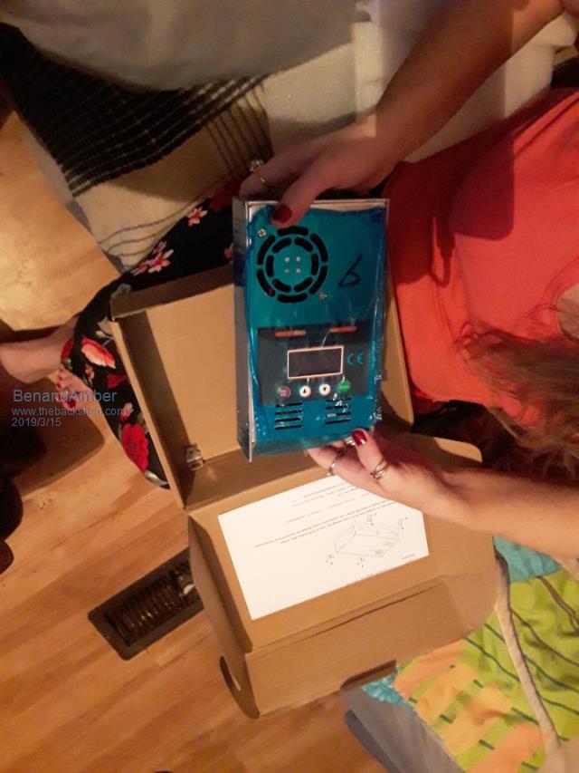 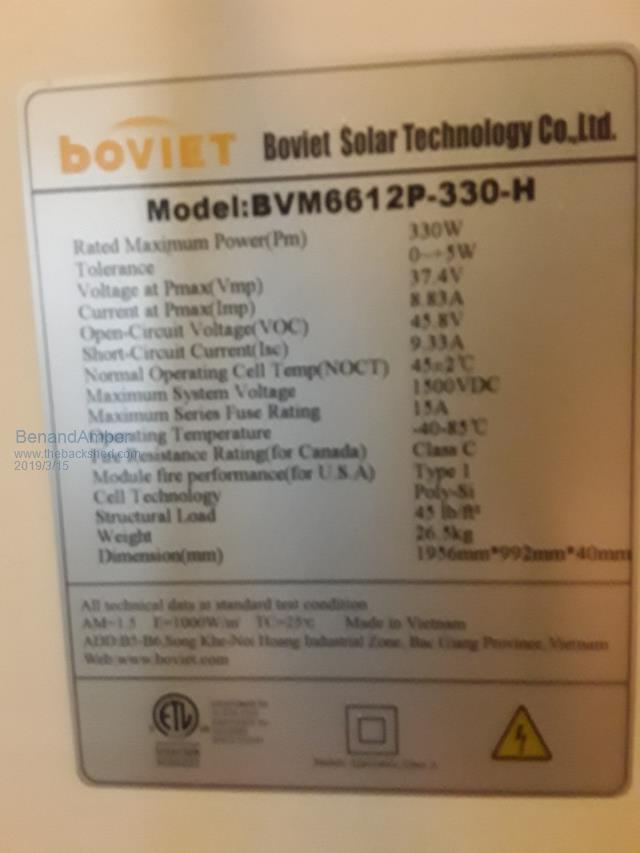 Poida I'm not trying to change the subject I know you don't need one I was really hoping that you would come up with a really good MPPT charge controller I know it isn't number one on your list since you don't need one I think it would help a lot of other people out I could be missing something here I read where you're better off matching your panels sometimes real cheap panels may not match but like I said I might be missing something here I may not be understanding or comprehending all of this For a example here is the name plate on the back of my solar panels Vmp37.4 ×2= 74.8 Imp8.83 ×0= 8.83 Voc45.8 ×2= 91.8 I'm going to be going with 48volt battery Bank 4 in series then parallel with the others 13.6 ×4= 54.4 Voc 91.8-54.4=37.4 Vmp 74.8-54.4=20.4 They are AMG 144 amp hour could this be a good match up to my batterie bank I just don't know enough about it to know I bought these because they were really cheap I couldn't afford them any other way the other picture is of one of three charge controllers I'll be using for now unless you come up with a better homemade one be warned i am good parrot but Dumber than a box of rocks |
||||
| Solar Mike Guru Joined: 08/02/2015 Location: New ZealandPosts: 1138 |
Hi BenandAmber. Try to put your figures into context.. Based on the PV panels you have, with their summed Vmp = 74.8v and Imp = 8.83 the total power output could be 74.8 x 8.83 = 660 watts assuming 100% efficiency and full sun. Your lead acid bank 4 x 12 volt batteries, when near flat the battery voltage = 44 volts, if you connected this direct to the panels via a PWM charge controller, the panel voltage would be pulled down to 44v at max 8.83 amps = 388 watts input power, so 272 watts are being wasted due to mismatch. As the bank charges up more to near 50% the voltage might be 12.3 * 4 = 49.2, so input charge power = 49.2 x 8.83 = 434 watts, so 225 watts being wasted. If you use a mppt controller, then this will better utilize that wasted power caused by voltage mismatch, but these are quite expensive for quality units. There are lower voltage PV panels that have a Vmp of 30 volts, these provide a better match and less power would be wasted. Paying top dollar these would be the ones to purchase if wanting to use a much cheaper PWM controller. If you were going to use several KW of your panels then the potential wasted power all adds up to quite a lot. However as they were cheap then just use a few more to compensate for not having an expensive mppt controller. For those of us using Lifepo4 banks the situation is much better, the near flat voltage = 48volts and 50% = 52.8, so PWM controllers working with 30Vmp panels work out quite well, there is no point in going to mppt. I'm currently re-designing my diy mppt controller, be at version 4, so has taken some effort to get it to where I want it, will post the design here when its all working 100%, few months away yet. Cheers Mike |
||||
| poida Guru Joined: 02/02/2017 Location: AustraliaPosts: 1419 |
SolarMike is developing a nice MPPT controller. I am looking forward to see his results. You have all you need already. 3 x MPPT controllers a 48V battery some panels. I would probably hook up pairs of those 37V panels in series to give about 74V at max power, and send that into the MMPT controllers. Split things into 3 so as to place the minimum power load on each of the controllers. How many of these panels do you have again? What is the current rating of the 3 controllers? These are Chinese so we probably won't want to run them anywhere near maximum current. Ever. And once you have things working for a few months, you can then see if it's worth it to make one or more of SolarMike's controllers and retire to the spare parts pile the Chinese controllers. That's how I would go. the controllers look like these ones wronger than a phone book full of wrong phone numbers |
||||
| BenandAmber Guru Joined: 16/02/2019 Location: United StatesPosts: 961 |
Thanks so much guys I have learned so much by reading what you guys have to say it is very much appreciated the controller's I have are the make sky blue controllers I've heard there same as in your link I'm going to use as many solar panels as I can fit on my RV I think I'm going to be able to fit close to 5,000 watts on top and was thinking about making a awning that folds down to the side of the bus when traveling if I can get this accomplished I could probably have 8000 watts I only have 8 144 amp hour AGM batteries currently my buddy is supposed to be able to get me another eight hoping because I cannot afford to buy them straight out these ones that I have our New Old Stock they were supposedly maintain though the stickers on the sides are late 2017 and you can tell that have never been used and are holding perfect voltage cross my fingers say a little prayer that I will be able to get the other eight if not I think my battery Banks going to be greatly undersized I've got lucky a few times I saved up all my wires and boxes if it wasn't for this there's no way I'd be able to afford to do this when I get a chance I'm going to take a picture of my 40 foot all aluminum 6 V 92 supercharged and turbocharged Detroit Diesel with around 80,000 miles on it Silver Eagle Motorcoach that I was truly blessed to be able to get for very little I made a lot of mistakes in life and I am very poor but I have a few skills and try to help everyone I can out regardless of their money situation someone has no heat they have no heat someone needs their house rewired because it's dangerous they need your house rewired has someone needs their washing machine fixed and have a few kids to go to school they don't have no money they still need a working washing machine I have been living by this code for about 11 or 12 years now and it's been good to me what goes around comes around especially if you're not expecting anything to come back around that goes to the good and the bad I truly believe this that goes to the good and the bad I truly believe this I have a hundred and seven solar panels left but half of them belong to my buddy we went in on them if I have my way about it when I parked it would look like airplane Wings folding out LOL thanks again you guys are God sent to us newbies really appreciate your guys's advice so peace happiness good health to you guys be warned i am good parrot but Dumber than a box of rocks |
||||
| Tinker Guru Joined: 07/11/2007 Location: AustraliaPosts: 1904 |
Ben and Amber, can you do me a favor please? When you do a long post please break it up into 3-5 line paragraphs. This makes the post sooooooo much easier to read for old eyes and it gets a chance to be read by me, instead of being skipped over  . .Have a look how others arrange their posts. Thank you. Klaus |
||||
| BenandAmber Guru Joined: 16/02/2019 Location: United StatesPosts: 961 |
Well try not to forget anymore tinker and thank you for your advice boy it's a big one isn't it I ramble on sometimes Peace love good health and happiness to you be warned i am good parrot but Dumber than a box of rocks |
||||
| azhaque Senior Member Joined: 21/02/2017 Location: PakistanPosts: 117 |
Poida, I am using the same board as you are. I need your help in setting the temp. at which the fan comes on. During testing I found that on my board, it comes on at 30 degC and switches off at 28 degC. Is that the same on your board? What should I do to raise the switch-on temp to 35 degC? TIA azhaque |
||||
| poida Guru Joined: 02/02/2017 Location: AustraliaPosts: 1419 |
I guess so, it's the same temp. The sensor is a 10K NTC thermistor. from some table I found: 28degC = 8867R 30degC = 8194R 35degC = 6752R We want to fool the 8010 and we can by altering the response of the thermistor to suit. Add a series resistor to the thermistor's wire, to bring it up a bit? Maybe a 1500R so something? Here is a schematic of the inverter board, it's close enough to be of some value. But clearly not exactly our boards. 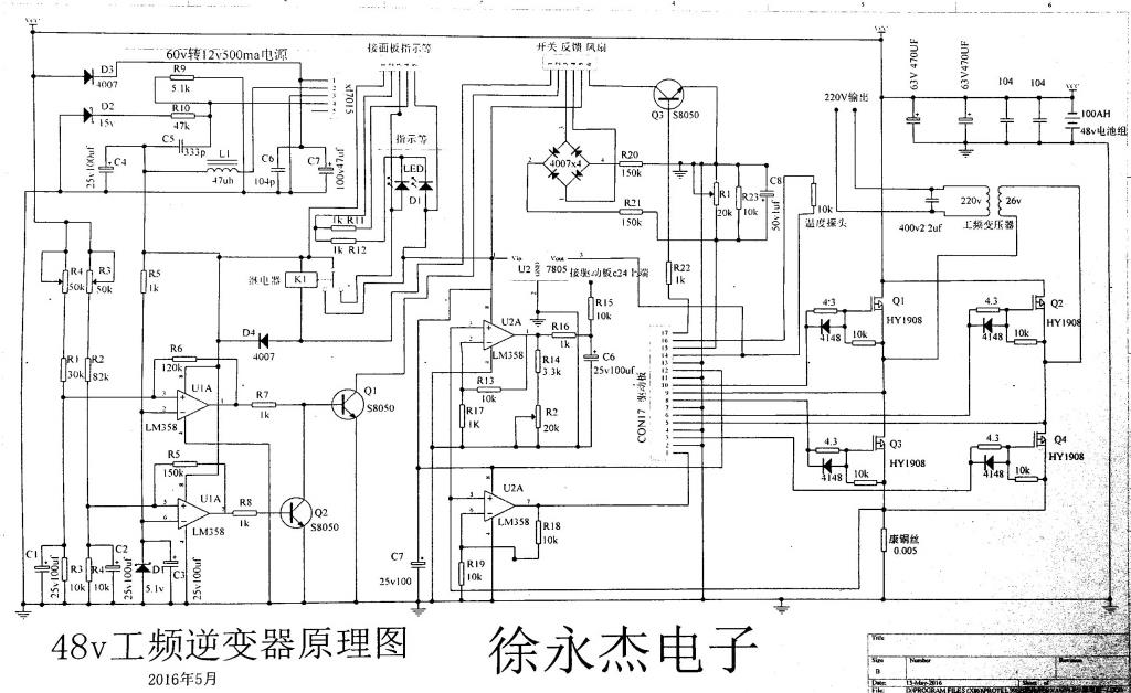 wronger than a phone book full of wrong phone numbers |
||||
| azhaque Senior Member Joined: 21/02/2017 Location: PakistanPosts: 117 |
Thanks Poida, for the response. I did a bit of research. Here is what I found. 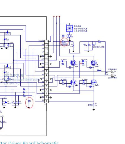 The above image is an excerpt from the EGS002 official paper. The temp. management circuit is composed of a 10K NTC thermistor and a 10K resistor WHICH IS SUPPOSED TO BE ON THE 002 BOARD as R22. The circuit has been highlighted. The front and back pictures of the 002 board are appended below FRONT 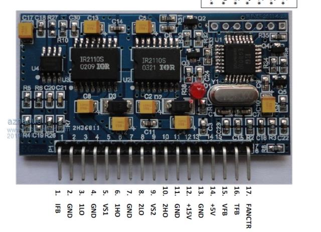 BACK 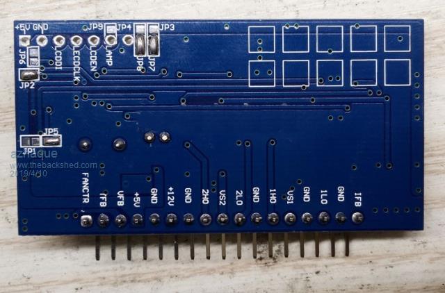 There is no R22, either in FRONT or the BACK. So it has to be on the main board OR THERE IS NONE. So putting a resistor, as you suggest will not help. Maybe it will have to be added. azhaque |
||||
| BenandAmber Guru Joined: 16/02/2019 Location: United StatesPosts: 961 |
Please keep posting on here what you guys find out I would like my fan to kick on at a lot lower temperature I think that's the same thing you guys were talking about Thanks for your time be warned i am good parrot but Dumber than a box of rocks |
||||
| azhaque Senior Member Joined: 21/02/2017 Location: PakistanPosts: 117 |
Ben Amber, Could you please put a voltmeter at PIN-16 and PIN-13 of the small board and measure the voltage as per the following photo. The voltage should rise to be around 4.3 vdc for the fan to start. In what you describe, you should see a voltage much lower than that value, preventing the fan to start. Thanks for your help. 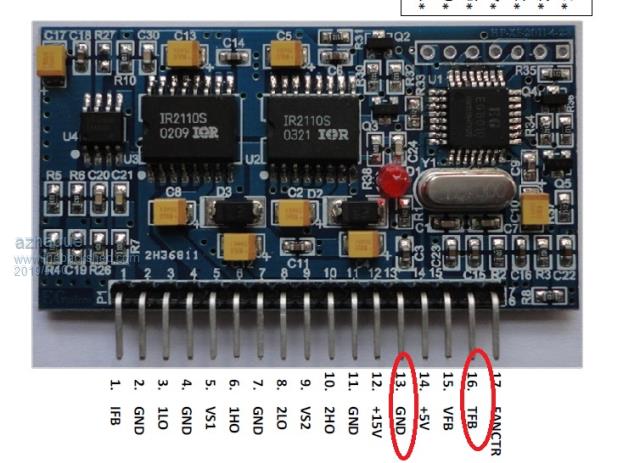 |
||||
| BenandAmber Guru Joined: 16/02/2019 Location: United StatesPosts: 961 |
I will hook it up when I get home later on tonight and try to get a measurement for you poida the Great or warpspeed might be able to help u there is other experts on here too but I'm just not one of them be warned i am good parrot but Dumber than a box of rocks |
||||
| poida Guru Joined: 02/02/2017 Location: AustraliaPosts: 1419 |
I have done this just now. (Volts at pin 14) (resistance of NTC thermistor), result, temperature from 10K NTC datasheet less than 3.4V, 4.88K, no fan, inverter running, 3.4V, 4.88K, fan commanded to run, inverter running, 44degC 3.17V, 5.9K, fan stopped, inverter running, 38degC 4.4V, 1.45K, inverter stopped, fan running, 80degC 4.2V, 2.0K, inverter started again, fan running, 70degC This was done with a 10K potentiometer with 5V at one end and pin 14 on the wiper, to simulate the NTC thermistor. wronger than a phone book full of wrong phone numbers |
||||
| azhaque Senior Member Joined: 21/02/2017 Location: PakistanPosts: 117 |
Poida, Thanks mate for the initiative. I begin my case with an excerpt from 8010 datasheet, given below 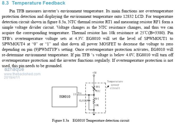 Please note that there is a NTC thermistor as well as a fixed 10K resistor connected to ground in the above figure (call it R(Var) for now). In the EGS002 datasheet that I attached a few posts above, R(Var) should be on the 002 board. But it isn't- not as far as I can see on the images. The result is that voltage divider is incomplete resulting in serious overheating of the heatsink as reported by Poida and BenandAmber which raises the temp of the heatsink to 80 degC. So what we need is a simple mod in the shape of a series combination of a fixed and variable resistor. I have modelled the values on an Excel Sheet that I append herewith. With a fixed 22K resistor and a 50K pot, one should be able to adjust the fan trigger temp anywhere between 25-50 degC. Below is the circuit. 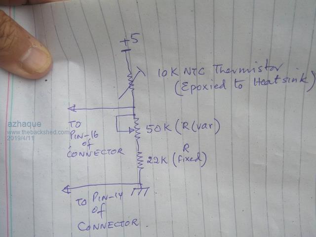 The two components can be soldered together and glued at a convenient location, at which the pot can easily be tweaked. Two leads- one to pin16 and another to pin14 are just the two connections to be made. Below is the Excel file 2019-04-11_215118_therm.zip Please note that the NTC thermistor values in the Excel sheet, have been taken from here Another mod that I would suggest is to connect a small 12volts relay to the fan output. The relay contacts should supply the current to the fans rather than running these off the on-board 12 volt supply which is likely to introduce all kinds of noise into the system. Regards azhaque |
||||
| azhaque Senior Member Joined: 21/02/2017 Location: PakistanPosts: 117 |
Read pin14 as pin13 (the Ground Pin) in the above post.  Sorry about that. azhaque |
||||
| Tinker Guru Joined: 07/11/2007 Location: AustraliaPosts: 1904 |
It seems to me that you are making something simple complicated, unnecessarily. The temperature feedback had been dealt with extensively some time ago, you (and any other newbies here) would do well to read the many earlier inverter builds on this forum. Anyway, it works as poida re discovered: the heat sink gets warm,the NTC senses that and turns on the fan. Now, the fan is supposed to cool the heat sink at this stage. If it cannot because the fan or the heat sink is too small then the heat sink gets hotter still. At about 60 degrees C, if I remember correctly, the EG8010 shuts down the output, as it is designed to do. It re starts when the heat sink cools down enough. I never experienced any problem with that while testing it. There never was any need to fit a potentiometer. However, if you are *really* worried that the heat sink is getting too hot for some reason, why not use an external temperature controller? I did suggest that to Ben in another post. In my two large inverters I use both, the EG8010 controlled fan blowing air into the inverter enclosure and onto the heatsink. And an independent temperature controlled fan, the sensor of which also senses the heat sink temperature, turns on a bigger exhaust fan. I set that to come on at a similar temperature. This way I get redundancy in case one cooling system malfunctions - has never happened so far. We have over 40 degrees C in my shed here in summer and the fans easily cope with that. Actually, they rarely run - it pays to use an adequately sized heat sink. BTW, I do not think epoxying the NTC sensor to the heat sink is a good idea. Use a clamp (miniature saddle like those to hold a cable) and heat sink grease to attach it. Any equipment I ever took apart *never* used epoxy to attach that sensor. Klaus |
||||
| BenandAmber Guru Joined: 16/02/2019 Location: United StatesPosts: 961 |
I haven't had a problem yet when I read this post I thought it would be cool to be able to have the fan kick on earlier then decided to go with redundancy by getting a temperature control module off of eBay like Tinker suggested in an earlier post I know that poida the great is pretty awesome and knows what he's talking about and Tinker is the same a few others on here that you can really depend on what they say is renewableMark and warpspeed I know nothing I am new to this I'm riding the coattails of the generous people on this site which when you're very poor is a lifesaver I'm sure I left a few really good people out so I apologize in advance I think a better statement would be the site is full of knowledgeable people that are more than willing to help if you are willing to listen Of course I'm one of those people that don't get a hint very well people need to tell me straight up hey dummy stop what you're doing and do it this way that works better for me tinker haven't seen no boat pics and haven't heard no boat stories about we're all you've been and all your adventures do you have a link or something where we good go and read and see some pics be warned i am good parrot but Dumber than a box of rocks |
||||