
|

|
Forum Index : Electronics : Rafael MPPT Controller (for WG Powerboard)
| Author | Message | ||||
| flyingfishfinger Senior Member Joined: 12/09/2020 Location: United StatesPosts: 110 |
Hi, I didn't want to derail Poida's thread about his MPPT so I'll put this here. I've adapted his Brainboard for Wiseguy's Powerboard layout to fit right ONTO the 10-pin connector in a bid to reduce cables running around the place & keep things short. I've made a few changes: - Added a hardware comparator & P-FET that could be used for a hard over-current shutoff. This is an adaptation of Poida's attempt at controlling this with a software interrupt, but I have no idea if it'll work yet. - Added a few 0.1uF capacitors to decouple the 5V supply to the Nano and the LCD, I want to try to get the I2C display working properly. Should generally reduce noise. - R, G & B LEDs - everyone needs Blinkenlights! For extra indicators. - Optimized routing for the 10uF filters a bit, this should reduce the noise on the analog readings. I don't have a 3D model of the Powerboard (wiseguy?) to check the fit with, but I'm 98% sure it'll fit. I'm about to order some along with the Powerboard, and if it works I'll be happy to share the Gerbers for anyone who wants to try it. In the meatime, here are schematic & screenshots if anyone's interested. I'll report back on how things go. 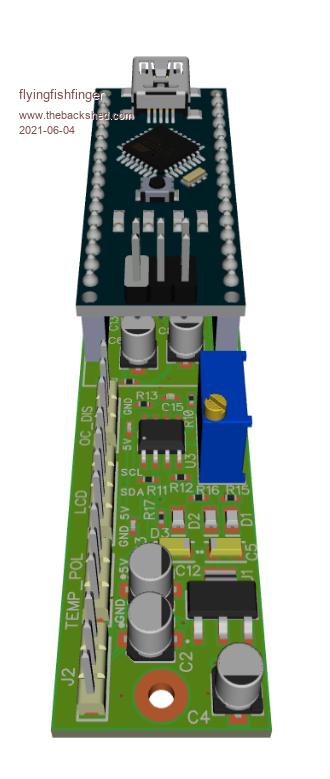 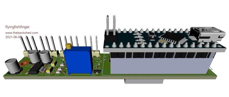 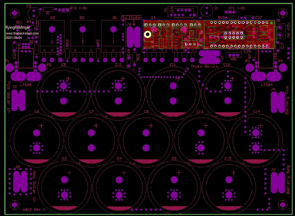 MPPT_NanoController.pdf Cheers, R Edited 2021-06-04 04:58 by flyingfishfinger |
||||
| wiseguy Guru Joined: 21/06/2018 Location: AustraliaPosts: 1156 |
"I don't have a 3D model of the Powerboard" Nor do I Rafael - sorry. I need to create 3D models for all of my components - its on my to do list - I can just see it if I use binoculars...... I do need to get around to it though - takes out a bit of the guesswork and I will need my vernier & sample components a lot less when I design PCBs. I have looked at how your pcb should fit and I dont think it will foul with anything. A component on my PCB could maybe be inserted on the underside if it helps. If at first you dont succeed, I suggest you avoid sky diving.... Cheers Mike |
||||
| flyingfishfinger Senior Member Joined: 12/09/2020 Location: United StatesPosts: 110 |
No worries. What program do you use for the designs? R |
||||
| poida Guru Joined: 02/02/2017 Location: AustraliaPosts: 1418 |
Rafael, here are a couple of photos of the built board, to help you see what space there is and is not. 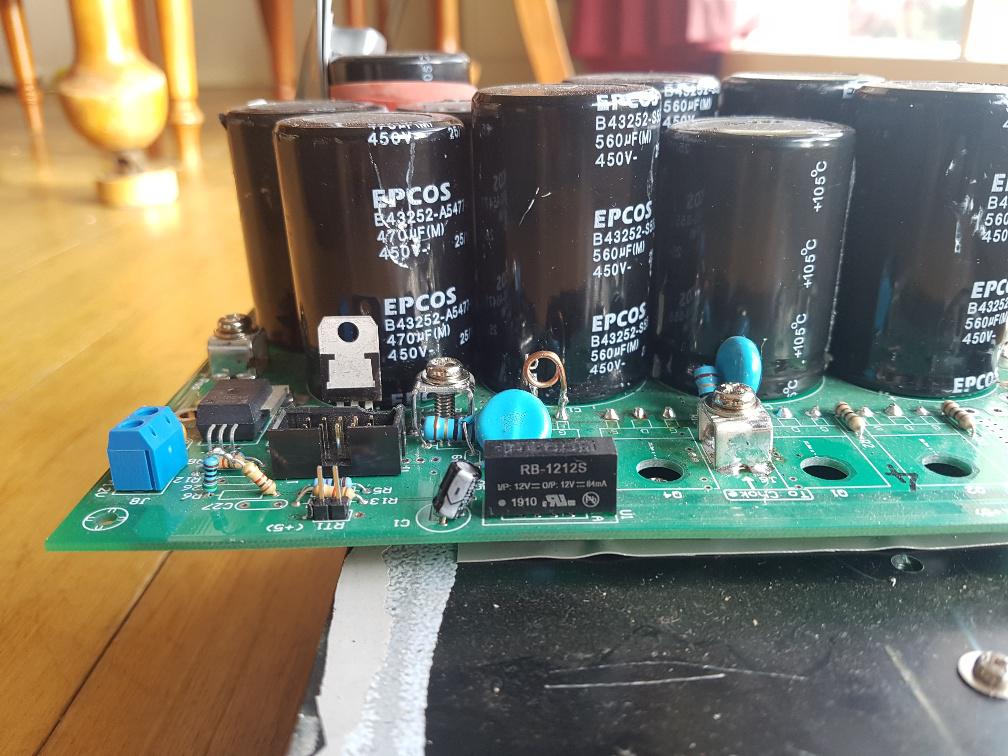 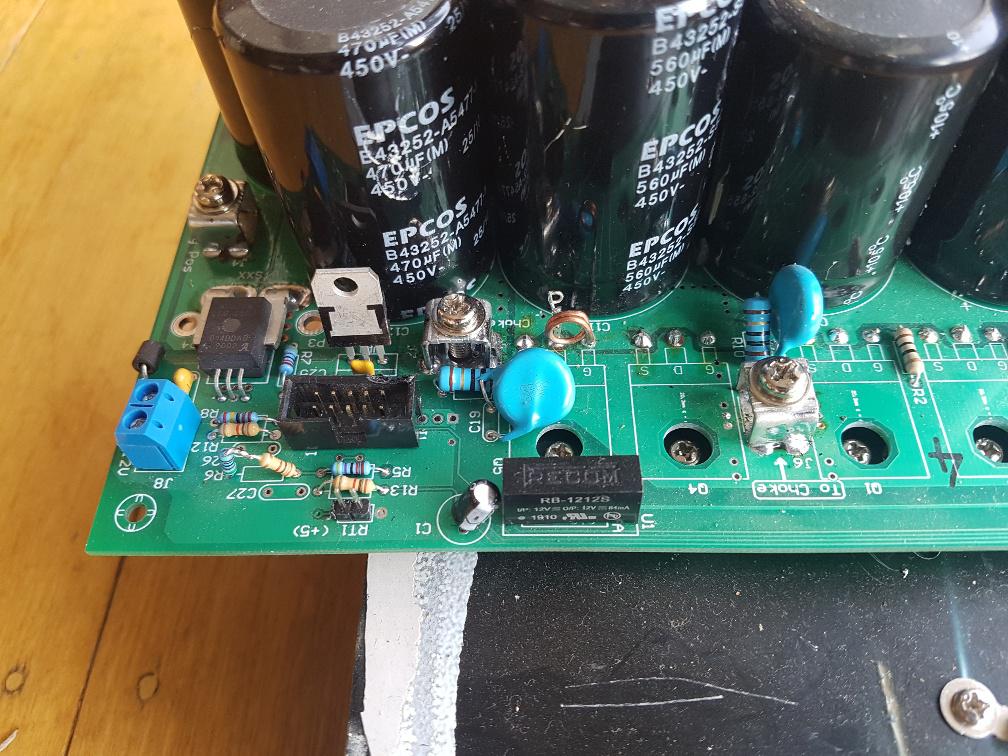 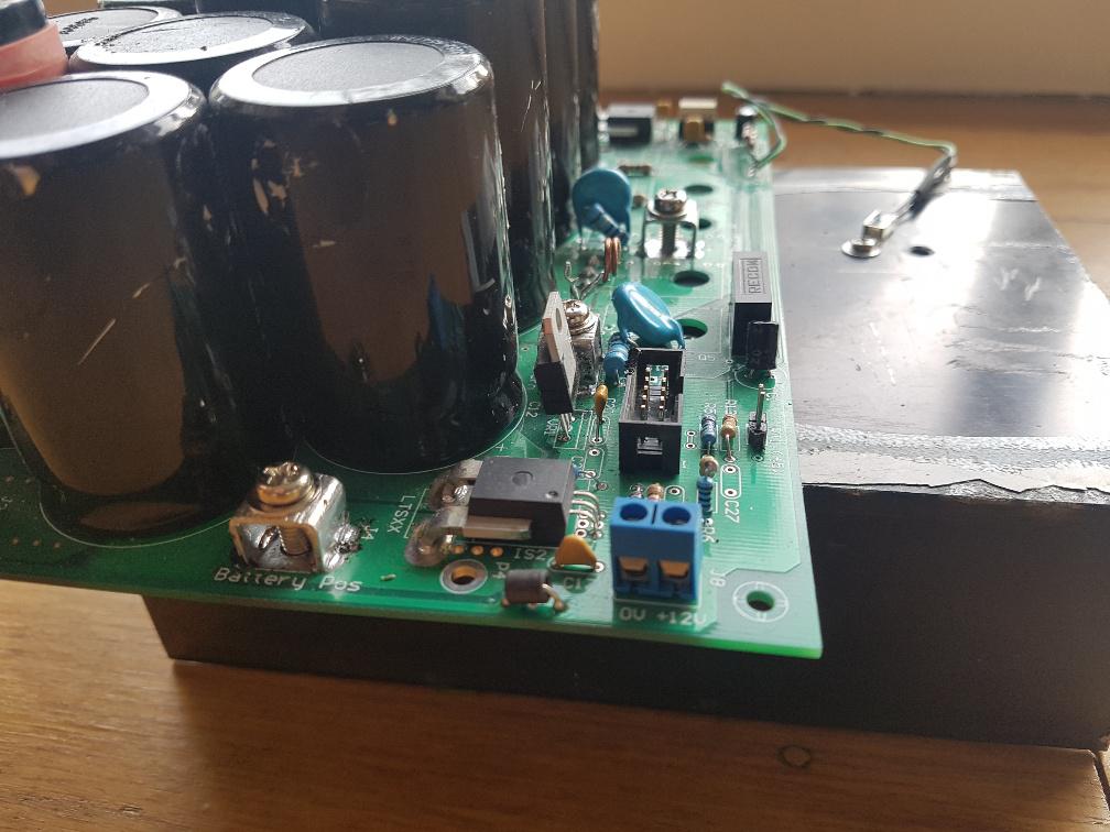 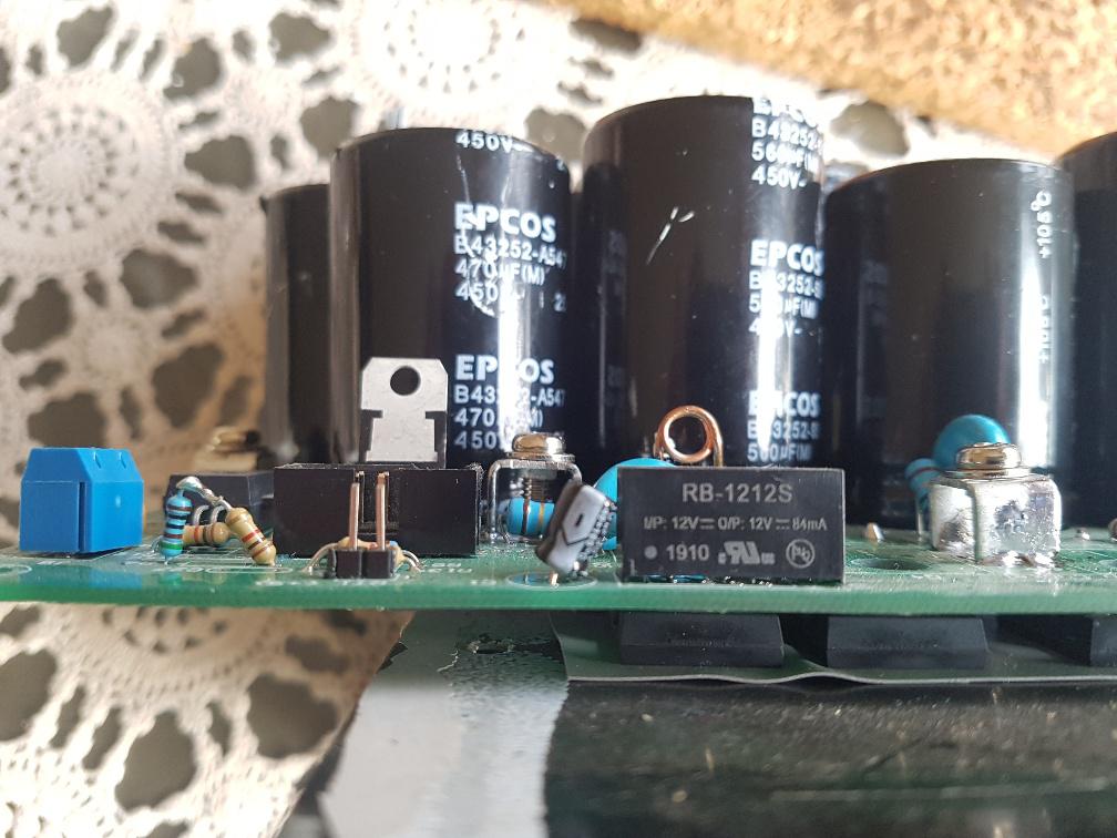 wronger than a phone book full of wrong phone numbers |
||||
| wiseguy Guru Joined: 21/06/2018 Location: AustraliaPosts: 1156 |
I am using Altium Ver 17. What do you use - the 3d imaging looks very good. If at first you dont succeed, I suggest you avoid sky diving.... Cheers Mike |
||||
| flyingfishfinger Senior Member Joined: 12/09/2020 Location: United StatesPosts: 110 |
I use Diptrace. Easy to use generally and the first thing I learned, so I do my personal projects in it. Adding 3D models is really easy there if it's not part of the standard libraries - click to add a STEP file to the footprint, align it and done. The images I posted are just screenshots out of the previewer, but I can save off nice STEP models of the full assembly. I'm surprised about Altium, it's known in the industry to have pretty good 3D output capability. I've never used it though so I'm uncertain how to set it up... FYI, I ordered both the Powerboard and my Controller PCB and I'm waiting on FETs from Aliexpress. Not sure what to do about the choke and caps yet, I have a lead on a busted Fronius but that's kind of up in the air. R Edited 2021-06-06 13:29 by flyingfishfinger |
||||
| flyingfishfinger Senior Member Joined: 12/09/2020 Location: United StatesPosts: 110 |
I got PCBs, check them out! MOSFETS from Aliexpress arrived too. Now I need order the rest of the parts... I haven't found anything to salvage a choke and heatsink from yet, sadly. Question: Did you guys end up putting a ferrite bead on each MOSFET gate pin? If yes, what size is it? R 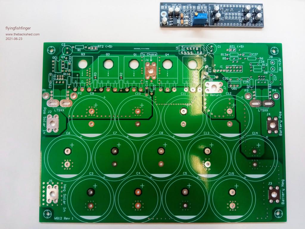 |
||||
| poida Guru Joined: 02/02/2017 Location: AustraliaPosts: 1418 |
In my builds no ferrite beads were used. If you can't find a choke then Digikey have them a couple of these at $15 AU each, probably $10 US will do. If I recall, one pair of those cores with 9 turns and about a 1mm gap in the inner core will be good for 2kW and about 20 Amps ripple when taking 100V down to 45V. maybe have a look at http://www.thebackshed.com/forum/ViewTopic.php?TID=12027&P=17#147582 and the later post at http://www.thebackshed.com/forum/ViewTopic.php?TID=12027&P=17#147632 Edited 2021-06-23 09:46 by poida wronger than a phone book full of wrong phone numbers |
||||
| flyingfishfinger Senior Member Joined: 12/09/2020 Location: United StatesPosts: 110 |
Cool, I'll just grab those then. Also, in your above pictures I see you're using a 1W 12V-12V regulator... but if this is used for the FET gate driver wouldn't we actually need more power? R |
||||
| poida Guru Joined: 02/02/2017 Location: AustraliaPosts: 1418 |
Driving the FET Gate is an operation that charges a capacitor. So the only energy needed is to drive the 10K Gate to Source resistor and to charge/discharge the FET's various capacitances, seen on the Gate pin. The time spent charging the Gate is about 600ns and average current is about 0.5 Amp for that period of time. See https://www.thebackshed.com/forum/ViewTopic.php?PID=103706#103706#103706 for a typical Gate voltage during switching. I show voltage across the Gate resistor so we can determine the current. (the Gate current really looks like it is charging a capacitor! See the exponential decay?) 20KHz PWM means 20K switch events per second. so that is a total of 20000 x 600 ns or 0.012 seconds spent delivering this 0.5 Amp. For the rest of the second, the Gate Drive bypass caps will be charging from the supply. It's about a 1% time driving the Gate and 99% of time recharging the bypass cap. Plus the 100% time spent powering the 10K Gate pulldowns. There are two. so that is 5K on 12V, 2.4mA I reckon the gate drive current needed is 2.4mA for the two 5K and 1% of 0.5A x 2 for the two FETS = 10mA so a total of 12.4mA @ 12V = 0.15W wronger than a phone book full of wrong phone numbers |
||||
| flyingfishfinger Senior Member Joined: 12/09/2020 Location: United StatesPosts: 110 |
You're right, I didn't do the diligence for my part selection. Here it is: The HY5110 has a total gate charge of 356 nC. We have a 10Ohm gate resistor in the design, so that means at 12V we can sink as much as 1.2A into EACH gate starting at t=0. At 1.2A, we will charge 356 nC in 300 ns (ignoring the Miller plateau and the fact that charging current drops as we turn on for the moment, so this calculation will be an overestimate). But if we have 2 (or even 3 FETs) and we want to switch them quickly, we will need 2.4 (or 3.6) amps if the driver can source this much. The FOD3182 can source 3A of current, so let's assume we've built with 3 FETs and are maximizing this current. That means we're delivering 36W for 0.006 seconds, for an average of 0.216W. If we populate 3 FETs and therefore also have 3.3k of pull-down, that's an additional 43mW for a grand total of 0.26W. The 10uF output capacitor will discharge to 11.89V at every cycle. For fun, I simulated a very similar MOSFET in LTSpice. The numbers roughly check out - the FET starts carrying the full drain current after about 300nsec, and the peak gate current is very nearly 1.2A: 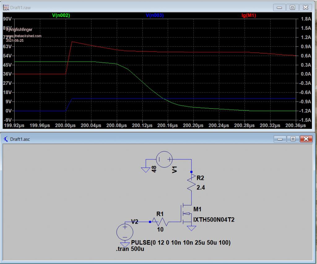 Cool! Thanks for promting me to do the analysis as well. On an unrelated note, what did you put between the FETs and the heatsink, some Sil-Pad esque material? R Edited 2021-06-25 05:37 by flyingfishfinger |
||||
| poida Guru Joined: 02/02/2017 Location: AustraliaPosts: 1418 |
Sil-Pad. It's good enough. The heat generation is mainly in the choke in my experience. Typical high power testing has shown HS temps of 40 C with a choke going to 50 C. These temperatures are attained only after an hour or so at 2kW + The mppt firmware will reduce output power linearly as the HS temp exceeds a user defined temperature. I think I use 60C as the start point and 70C as the end point. Power will be 100% converted at 60C and lower and then it will be reduced to zero at 70C, following a linear rate of change. This makes it nearly pointless to have a fan on the heatsink. I found HS orientation to be "worth" a fan if you have the HS fins vertically aligned to allow air movement up and out the top. here is some data from my home system. The output current and HS temperature for the mppt connected to the 3kW North facing array. I see no way the HS will exceed 60 C even if running at 40 Amps all day. But this of course is highly dependent upon the HS size and the HS used with this mppt is the same size as that shown in the above photos. wronger than a phone book full of wrong phone numbers |
||||
| flyingfishfinger Senior Member Joined: 12/09/2020 Location: United StatesPosts: 110 |
Sneak peek - still need to find wire to wind my choke and I don't really have a useable heatsink for the FETs :/ 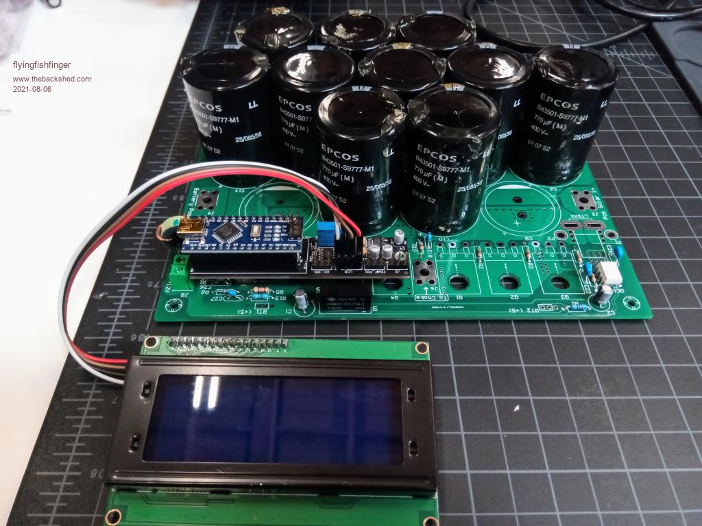 The LCD works from the controller board, but I haven't tested anything else yet... R EDIT: Shattered one of my new cores trying to gap it, guess testing is going to have to wait...  Edited 2021-08-06 10:18 by flyingfishfinger |
||||