
|

|
Forum Index : Electronics : $10 Inverter Scope
| Page 1 of 3 |
|||||
| Author | Message | ||||
mackoffgrid Guru Joined: 13/03/2017 Location: AustraliaPosts: 460 |
Inspired by some of Tinkers posts / photos of his DSO138 and the STM32-O-Scope I thought a dedicated, SIMPLE Scope displaying our Inverter's output waveform would be nice bit of bling. 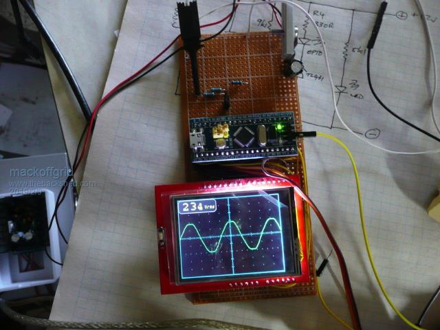 The "Blue Pill" stm32F103C8 is only $AUD 2.50 and the 2.4' LCD is about $AUD 5.80, PCB will only be a couple of dollars. This is my first project with the STM32duino, I had to repair the BluePill, ordered the wrong programmer, got the parallel LCD instead of the SPI LCD  But it all came together. But it all came together.It is a fixed timebase of 5ms/div and fixed Volts per Div and fixed trigger of rising over the zero line. Its rock steady on my test of a transformer secondary. It also has a persist feature (indefinite) or not, I thought it would be good to pick up interesting events. Having said that this is definitely not, obviously, a piece of test gear. 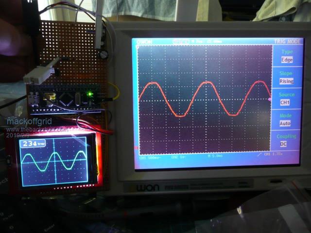 I believe the STM32F103C8 has dual ADC (not all micros in this family do), if so I see no reason why I couldn't read in AC current and maintain my current conversion rate, and incorporate display for RMS current and Power. Additional features I'd like to investigate is Distortion / Spectral chart. 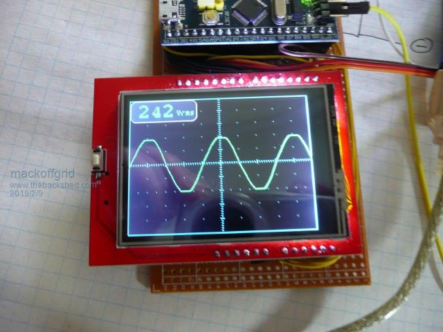 Add a ZMPT101B 2mA:2mA transformer and maybe a rail to rail opamp, maybe one of modules Transformer Module do the job? WiseGuy might know? A bit more tidy up to do on the code, I need to draw the PCB, if anyone is interested I'll put it up on Github or something. Cheers Andrew |
||||
| davef Guru Joined: 14/05/2006 Location: New ZealandPosts: 499 |
Hi Andrew, Would be a nice project to get into the STM32 world. Could you post links to the actual "Blue Pill" you used and the LCD? Would a ST LINK V2 be able to program the micro? Thanks, Dave |
||||
mackoffgrid Guru Joined: 13/03/2017 Location: AustraliaPosts: 460 |
Hi Dave I don't have a ST-Link V2, yet, I accidentally ordered the usb serial thing instead. They both will work. I do have the ST-Link V2 on order and will confirm it. I bought my Blue Pill over a year ago, probably on ebay since I can't find it in my "Orders" on aliExpress. "Blue Pill" is the cheapest free delivery I could find. 2.4" parallel LCD is the actual LCD I Ordered. ST-Link-V2 is the I have ordered. And just to confuse things, I have ordered this 3.5" 320x480 LCD to try out, it uses a different controller so I'll probably have some working out to do. I'm just implementing the second ADC now to simultaneously (within a couple of cycles @72Mhz) sample current as well. I figure with the bigger LCD - it would make a Power Scope. Cheers Andrew |
||||
| wiseguy Guru Joined: 21/06/2018 Location: AustraliaPosts: 1156 |
Hi Andrew, Well done with the digital waveform monitor a bit more code and we can enter the digital CRO market.... I have attached a suggested circuit for full wave amplifying and rectification of the small ZMPT101 transformer, with a Vpeak DC output. I was inspired by the second circuit but I added gain in the second stage & finally another approach in the third circuit for interest (R1 = R2). All will work ok on many single supply op amps. I have bread-boarded it and it works fine. The dual opamp I used is an LM358 which is cheap & will operate down to the neg rail on the input (important) as when the input of the first stage goes below ground the output goes positive with an equal and opposite level which is also fed to the second gain stage. The positive input part of the signal is passed directly to the second stage via the 2 gain setting resistors (R4,R5) as D1 is now reverse biased. The second gain stage simply multiplies the first stage between 1 - 3 times for calibration with VR1. The Ali Express module PCB with amplifier is an AC output and its output appears to swing up and down from half the supply rail & for your application it should work well I think. Sorry - I went off at a tangent as I am after DC and you are after AC but thought I would leave the rest here anyway. 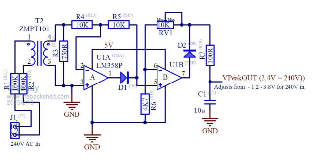 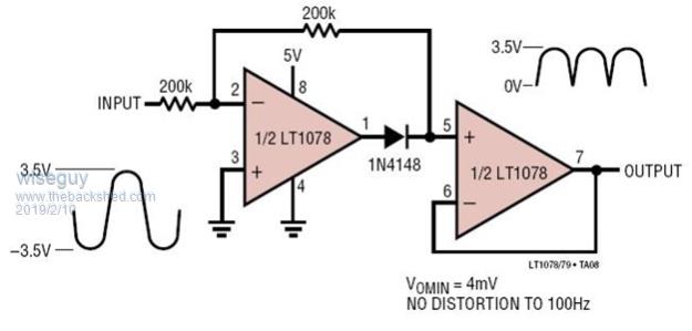 If at first you dont succeed, I suggest you avoid sky diving.... Cheers Mike |
||||
| wiseguy Guru Joined: 21/06/2018 Location: AustraliaPosts: 1156 |
FYI here is the actual circuit which I believe is used in the Ali Express module  If at first you dont succeed, I suggest you avoid sky diving.... Cheers Mike |
||||
mackoffgrid Guru Joined: 13/03/2017 Location: AustraliaPosts: 460 |
Gday Mike Thanks very much for the schematic of the aliExpress module. Saves lots of time. I couldn't build that module anywhere the price they sell them for. Also thanks for the other reference schematics. I've several other projects where these become useful. Cheers Andrew |
||||
| LadyN Guru Joined: 26/01/2019 Location: United StatesPosts: 408 |
I really cant wait for you all to check this thread out: $10 O-Scope revisited 2Mhz bandwidth, 2Msps with ability to export captures. I am starting to love this and we should all build this! |
||||
| LadyN Guru Joined: 26/01/2019 Location: United StatesPosts: 408 |
http://www.stm32duino.com/viewtopic.php?f=19&t=107 |
||||
mackoffgrid Guru Joined: 13/03/2017 Location: AustraliaPosts: 460 |
I enjoyed reading through STM-O-Scope and the DLO-138 topics on stm32duino.com. My project is all about using the cheap "Blue Pill" and cheap 2.4" LCD and making a simple Panel mount Scope, as a fixture, for an inverter or plant room. As usual, I've discarded all the available code and started from scratch, obviously influenced by, particularly the STM-O-Scope. (I did pinch the code for drawing the graticule). I have now implemented the second ADC and is running in "DUAL" mode which means that the ADC's are sampling and converting simultaneously - Cool. The syncing is amazing solid, I leave it running in persistence mode all night and the trace just gets a little thick! Its far from finished but I'll attache the code as it is now for interest. I'll do a schematic in the coming days as well. 2019-02-12_082155_Libraries_for_InverterScope.zip 2019-02-12_082225_InverterScope_002.zip I often have a references tab in my code where I keep info and urls to all the libraries and ideas used in a project. I have done that this time and have tried to make it complete - enjoy. Cheers Andrew |
||||
| davef Guru Joined: 14/05/2006 Location: New ZealandPosts: 499 |
Great stuff! I found this 3.2" on Aliexpress: 3.2" TFT SPI ILI9341 Dave |
||||
| davef Guru Joined: 14/05/2006 Location: New ZealandPosts: 499 |
Andrew, Is STM32ADC.h somewhere in your files or do I need to include some other libraries in the project? Thanks, Dave |
||||
mackoffgrid Guru Joined: 13/03/2017 Location: AustraliaPosts: 460 |
Dave, it is part of the standard core libraries. These are the instructions I followed (more or less). Installing STM32duino I set up a new install of arduino and used the portable mode. Its a bit wastefull on hard disk space but I like things to be compartmentalised. Arduino Portable Install Cheers Andrew |
||||
mackoffgrid Guru Joined: 13/03/2017 Location: AustraliaPosts: 460 |
Dave, I think we can get most of the LCDs going - famous last words  . .That LCD has a SPI interface, no reason why it won't work - needs a different library. I've ordered this 3.5" parallel LCD which is not much more expensive than the one you spotted, and its pin compatible with my 2.4" lcd. Cheers Andrew |
||||
mackoffgrid Guru Joined: 13/03/2017 Location: AustraliaPosts: 460 |
By the way, I didn't install the USB drivers. In my haste, I soldered the pins on the "blue pill" only to find out later that a smd resister has to be replaced, its a usb pulldown I think, it needs to be 1k5 but they build them with a 10k - hard to change with the pins on. Consequently I couldn't get the USB to work - no matter don't need it. The "blue pill" comes with a (Hard Coded, I think) serial boot loader. Its fast enough and seemed to work well. 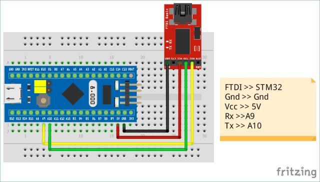 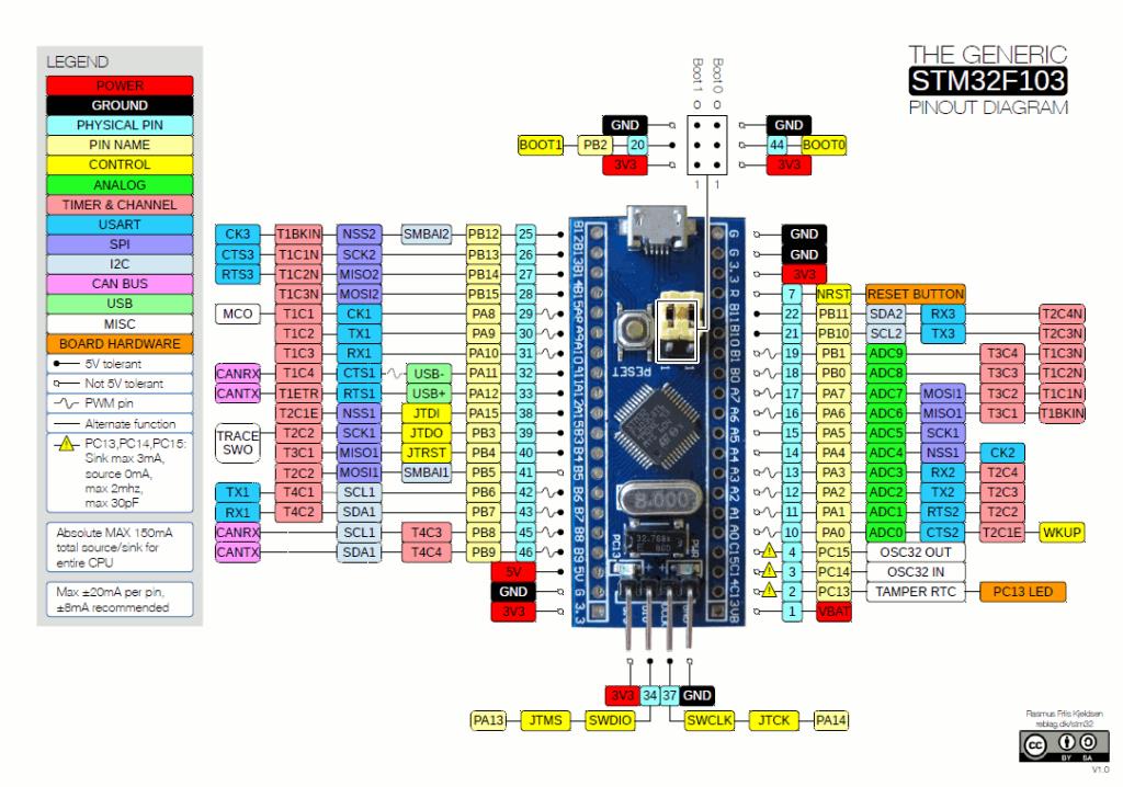 I do like the pin numbering with stm32Duino, it uses the proper port names rather than a meaningless number. Cheers Andrew |
||||
mackoffgrid Guru Joined: 13/03/2017 Location: AustraliaPosts: 460 |
The LCD backlight chews a bit of power, my linear regs are getting a bit hot. So Im looking at these tiny smps @ 35 cents plus post. I got some of the LM2596 as well. 5 modules for $4 inc post, I cant complain. Some LCD's seem to want 5v and others want 3v3. Cheers Andrew |
||||
| davef Guru Joined: 14/05/2006 Location: New ZealandPosts: 499 |
Hi Andrew, I did an install of the Arduino IDE on a 64 bit machine and haven't used it yet. I'll check out the portable install as this machine will probably only end up for Arduino work. Thanks for the added documentation, I can see I have my work cut-out for tonight :) |
||||
mackoffgrid Guru Joined: 13/03/2017 Location: AustraliaPosts: 460 |
I have drawn up a schematic in Eagle. I have included both types of LCD. The schematic is compatible with Andrew Hull's STM-O-Scope using the SPI LCD. 2019-02-13_162302_PowerScope.pdf 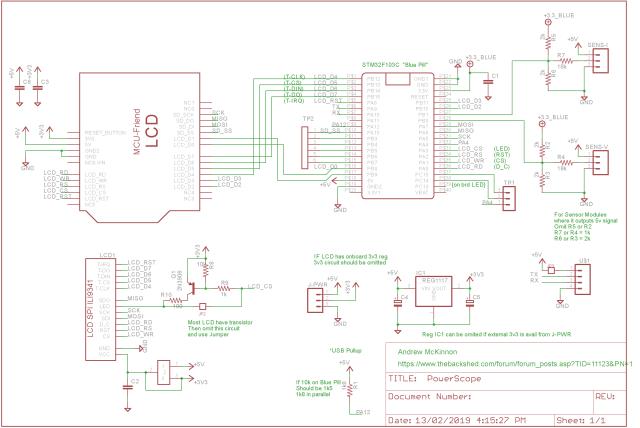 Cheers Andrew |
||||
| davef Guru Joined: 14/05/2006 Location: New ZealandPosts: 499 |
Hi Andrew, Thanks for the schematic. Just one question, I am using Generic STM32F10C series in the board manager and I get the following error: /home/davef/Arduino/InverterScope_002/InverterScope_002.ino:12:26: fatal error: Adafruit_GFX.h: No such file or directory #include <Adafruit_GFX.h> I tried changing that to #include <Adafruit_GFX_AS.h> but still no luck. Running Linux and as it finds Streaming.h I think I have the libraries in the right place. Cheers, Dave |
||||
mackoffgrid Guru Joined: 13/03/2017 Location: AustraliaPosts: 460 |
Hi Dave, adafruit_GFX_AS is a red herring, sorry. 2019-02-13_181725_Libraries_for_InverterScope.zip Adafruit-GFX-Library is the library you need and is included in the zip above. (btw, my arduino install is on Windows - my Linux skills are very basic) Cheers Andrew |
||||
| davef Guru Joined: 14/05/2006 Location: New ZealandPosts: 499 |
Got it. Now wait 1-2 weeks for my STM32 dev boards to arrive. Thanks for your help. Dave |
||||
| Page 1 of 3 |
|||||