
|

|
Forum Index : Electronics : 8 KW Inverter Build
| Author | Message | ||||
Madness Guru Joined: 08/10/2011 Location: AustraliaPosts: 2498 |
My Inverter has been running but it does not seem to perform quite as I expected. A minimal load of approximately the Toroid is about 25 degrees above ambient temperature. The only PCB I have been able to get to run successfully has been with TO220 4110 MOSFETs. Any PCB with TO247 IRFP4110's and just this week I also tried HY4008W's all work with up to 3 MOSFETs in each bank, however with load I get blips at zero crossing and the sine wave gets a squiggle on it. Adding more MOSFETs results in quite savage spikes particularly once the wave crosses 0. Which seems to indicate that the IR2110 is not able to drive more than 3 gates of these MOSFETs. ( I know the 4110 TO220 & TO247 should be the same) On this Chinese Inverter PCB there are MOSFETs on the gate drive and they have only 5 MOSFETs on each leg. I am considering adding this gate drive circuit. I am no Electronics Engineer so I am hoping someone might comment on this. 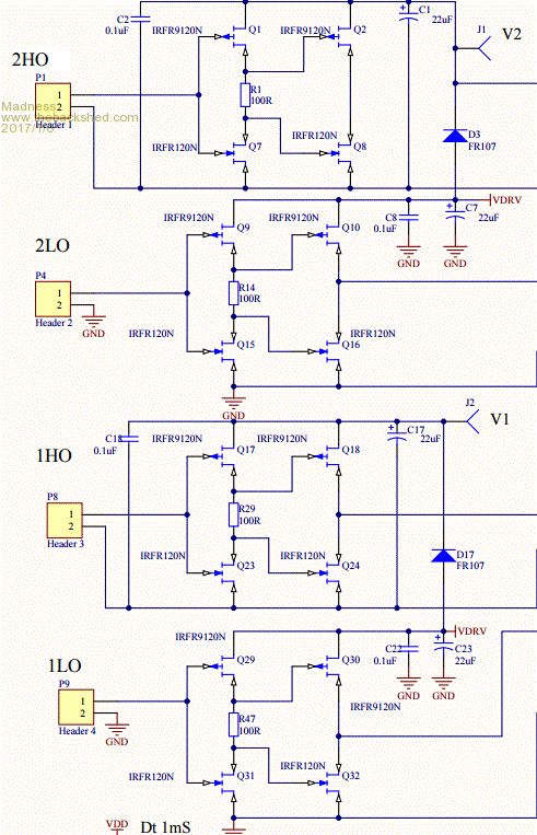 The full circuit can be found here, it uses the EG8010 chip also. There are only 10 types of people in the world: those who understand binary, and those who don't. |
||||
| Warpspeed Guru Joined: 09/08/2007 Location: AustraliaPosts: 4406 |
|
||||
oztules Guru Joined: 26/07/2007 Location: AustraliaPosts: 1686 |
I'm not an EE either....but the top driver cant work, as the drive output to the fets is turned on all the time.... needs redrawing. Apart from that I can't see anything glaring at me. I don't fully see why they have done it that way for a totem driver..... but I lack the knowledge to refute the system. The chinese one looks more like the set up I would do. Maybe Warp can fill us in on the nuance of it all. I would be concerned that any toggling of their on off switch ( in the pointed too circuit) would kill the fets due to them being able to turn the driver stage on and off without direct correlation with the 8010 chip.... ie can we make sure the driver is on before the soft start is initiated. On first start then yes, but a brief interruption may leave the 8010 running, whilst the driver stutters with switch bounce... this will lead to a disaster for the fets trying to drive the transformer torroid at an indeterminate start position. I have some tiny wiggle in the wave at about the 30degree point on the latest one I built. It still runs normally, driving huge loads without problem, but it annoys me why it is there on this unit. Will get another transformer built today or tomorrow, and try a few things to isolate how and why we get differing results from unit to unit. They all work very very well.... but why the minor differences I will leave my drivers the same unless I can isolate them as the cause... but for now simple seems to work just fine. I am wondering if it is the little transformer and circuit that does the VFB that can create inconsistencies in the different boards. The wave form on paper in the spec sheet for the 8010 is complex, but the 4u7 on the rectified outputs makes my wave a bit flatter, and maybe that is used in shaping the spwm Will try different values to see how it effects the wave. Village idiot...or... just another hack out of his depth |
||||
| Warpspeed Guru Joined: 09/08/2007 Location: AustraliaPosts: 4406 |
Yes the top driver has a glaring drawing error, that needs to be fixed. To see what is wrong, compare it to the other three directly below, which appear to be correct. The output should come from the junction of Q2 and Q8 drains. When building something like this, the layout and how it is physically put together is as vitally important as the actual schematic. Grounding is particularly important, and some interconnections need to be kept very short and direct, and kept well away from some other things. Its not really possible to give a simple list of do's and dont's. Something like this is definitely not a beginners project, and even for the experienced, its full of possible potential problems if an existing working prototype is not copied exactly. I try to keep out of these things, because from long experience, any criticism of someones efforts at construction, often does not go over very well. Cheers, Tony. |
||||
Madness Guru Joined: 08/10/2011 Location: AustraliaPosts: 2498 |
|
||||
| Warpspeed Guru Joined: 09/08/2007 Location: AustraliaPosts: 4406 |
O/k thanks. It sounds like a reincarnation of the same inverter, or at least a similar operating principle. As you will already know, it does not use PWM, but combines the output of three separate very simple square wave inverters to generate all the steps. Cheers, Tony. |
||||
Madness Guru Joined: 08/10/2011 Location: AustraliaPosts: 2498 |
Thank you for the Oz & Warp for your input I see the error you are referring to. Here is some information from International Rectifier which talks about the same thing but only shows a circuit for the low side. "7. HOW TO BOOST GATE DRIVE CURRENT TO DRIVE MODULES Modules and other paralleled MOS-gated power transistors at times require more current and lower gate drive impedance than what a typical MGD can provide. The high input impedance power buffer shown in Figure 11 delivers 8 A peak output current. It can be mounted close to the power module, thus reducing the inductance of the gate drive loop and improving the immunity to dv/dt induced turn-on. It draws negligible quiescent current and can still be supplied by a bootstrap capacitor. The buffer receives its drive signal from the IRS2110 or an MGD with lower gate drive capability, and drives an IGBT module which has a total gate charge of 600 nC. Q1 and Q2 are low current drivers for Q3 and Q4 which can be sized to suit the peak output current requirement. When the input signal changes state, R1 limits the current through Q1 and Q2 for the few nanoseconds that both transistors are on. When the input settles to its new state, the driver transistor quickly discharges the gate capacitance of the conducting output transistor forcing it into off-state. Meanwhile the gate of the other output transistor will be charged through R1; the turn-on will be delayed by the RC time constant formed by R1 and the input capacitance of the output transistor." 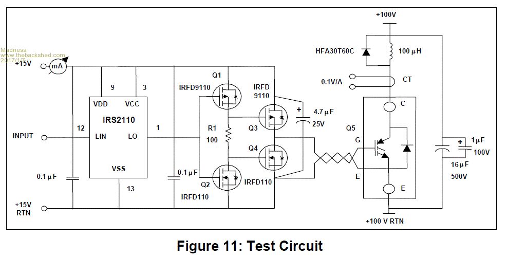 The complete PDF is attached. 2017-01-07_012507_an-978.pdf Warp any input is appreciated and no offence will be taken. There are only 10 types of people in the world: those who understand binary, and those who don't. |
||||
Madness Guru Joined: 08/10/2011 Location: AustraliaPosts: 2498 |
It sounds like a reincarnation of the same inverter, or at least a similar operating principle. As you will already know, it does not use PWM, but combines the output of three separate very simple square wave inverters to generate all the steps. I have searched and searched over the past few years to find service information about these Inverters but apparently everyone who had it had to swear their life away to receive it. Trace was taken over by Xantrex and then Schneider took over Xantrex, there was a very good forum the Xantrex site but was all taken down with the take over. The Trace I have been using up til now was built in 1998 and has worked flawlessly apart from the odd overload shut down. One part I really liked is how it interfaces with a generator and can sync to it with completely seamless switchover. As that is not an option with these DIY Inverters I will be looking at converting a 10KW induction motor into a 48 volt generator by rewinding it to a suit the 48V battery bank and run it as an induction generator with a 3 phase rectifier. There are only 10 types of people in the world: those who understand binary, and those who don't. |
||||
| Warpspeed Guru Joined: 09/08/2007 Location: AustraliaPosts: 4406 |
Madness, That is all true, but IR never made a gate driver chip with real balls. So they are suggesting cobbling up some extra mosfets, which will work, but it is a bit messy. A better way is to use something like a TC4452 twelve amp non inverting driver chip and a 1.0 ohm series gate resistor mounted right up close to each mosfet. We are talking about driving some very large mosfets here, with maybe up to 10nF gate capacitance. http://ww1.microchip.com/downloads/en/DeviceDoc/20001987C.pdf Then parallel up all the TC4452 inputs, and drive that with your IR isolated gate driver. Put the TC4452's in machined contact sockets. If a mosfet blows it sometimes takes out the gate driver chip, but not always. So a socket is worth the effort. Also unplugging the individual driver chips, means you can test each mosfet gate for shorts without having to unsoldering each mosfet to do it. These driver chips are not cheap, about $5.00 each I think. But they will drive just about anything, and are very fast. Cheers, Tony. |
||||
Madness Guru Joined: 08/10/2011 Location: AustraliaPosts: 2498 |
Thanks Tony, I have already ordered the bits to make the circuit I have posted, my plan is to make a couple small sub boards and mount them on the back of the existing PCBs I have built. Then I can cut into the existing gate drive circuit, it might be a bit more messy but this will save having to redo the whole lot from scratch. However I will keep the TC4452 in mind if I get to the point where I am making new PCB's. Your comment about the IR2110's not having real balls is interesting, I have seen it over and over where I can drive 3 MOSFETs perfectly well on each leg. Yet Oz is doing fine with 6 on each leg, I have one working PCB with all 24 MOSFETs on it which are the TO220 4110's. They have longer legs due to the way they are mounted compared to the boards I have with the TO247 IRFP4110's which have only 3 or 4 mm between the case and PCB. They are supposed to be the same apart from the case. There are only 10 types of people in the world: those who understand binary, and those who don't. |
||||
| Warpspeed Guru Joined: 09/08/2007 Location: AustraliaPosts: 4406 |
[quote]I have searched and searched over the past few years to find service information about these Inverters but apparently everyone who had it had to swear their life away to receive it. Trace was taken over by Xantrex and then Schneider took over Xantrex, there was a very good forum the Xantrex site but was all taken down with the take over. The Trace I have been using up til now was built in 1998 and has worked flawlessly apart from the odd overload shut down. One part I really liked is how it interfaces with a generator and can sync to it with completely seamless switchover. As that is not an option with these DIY Inverters I will be looking at converting a 10KW induction motor into a 48 volt generator by rewinding it to a suit the 48V battery bank and run it as an induction generator with a 3 phase rectifier. You are way ahead of me in all this, I have never actually seen or worked on any of those particular inverters, so have no idea of how specifically they work. They should not be too difficult to reverse engineer, the idea behind them is not too complicated to understand, but there are at least a couple of different ways to go about it. I have designed and built several of these stepped waveform inverters myself, and with great success. Using a home built one myself right now in fact. As you say, they are brilliant at handling highly reactive loads, and for syncing to another ac power source, because they are completely bi directional. They tend not to blow up when you throw a lot of out of phase current back at them. I don't want to hijack this thread, so will not say any more. For some reason there seems to be little or no interest in anything other than microcontroller derived high frequency PWM inverters. Cheers, Tony. |
||||
Madness Guru Joined: 08/10/2011 Location: AustraliaPosts: 2498 |
Just connected a Aero-Sharp Grid Tie Inverter with 1500W of panels to the Inverter today. All went well, no fuss, no sparks, no bangs it just worked. At 3:30 with light cloud it was producing nearly 600W which I thought was quite good for the conditions. There are only 10 types of people in the world: those who understand binary, and those who don't. |
||||
oztules Guru Joined: 26/07/2007 Location: AustraliaPosts: 1686 |
Perhaps try the aerosharp/s on your 240v generators... rectify and input as solar 340v. May save you rewinding the induction motor. ..........oztules Village idiot...or... just another hack out of his depth |
||||
Madness Guru Joined: 08/10/2011 Location: AustraliaPosts: 2498 |
The 8KVA Lister generator I have is worth quite a bit of money so I plan to sell it for that reason. I have a 2 Cylinder water cooled Diesel engine that would be ideal to drive the proposed rewound generator. It has electric start and is much quieter than the Lister also. Another factor is I have been told rectifying the AC output only clips the tops off the AC wave which apparently is not so good for the generator. If I rewind with a larger than needed 3 phase motor I will have windings as heavy as I can get them. Although having said that the generator on the Lister is a 12 wire type that can be configured as a 3 phase and has a bit more head room when configured that way rather than single phase. Also I have a 10KW Onan Diesel generator which is a bit more thirsty if needed. There are only 10 types of people in the world: those who understand binary, and those who don't. |
||||
Madness Guru Joined: 08/10/2011 Location: AustraliaPosts: 2498 |
So much for the grid tie, the Aero-sharp spat the dummy when it attempted to make more power than I was consuming. It errored saying PV is too high, yet it is <300V also the GT and main inverter where making horrible sounds till I disconnected the AC to the GT. I tried it with the Trace Inverter after Warp mentioned how that type of inverter can easily go bi-directional. That did not go down well with the GTI and my PV charge controllers shut down and were screaming that I had a ground fault. There are only 10 types of people in the world: those who understand binary, and those who don't. |
||||
oztules Guru Joined: 26/07/2007 Location: AustraliaPosts: 1686 |
That is just ..... well I don't get it at all. Been a while since I did grid tie, as I have changed out the aerosharps to a single growatt recently, but until then it was normal to use 4.5kw of solar on the grid tie. Sometimes it was a 1k5 and 3kw aerosharp, sometimes three 1k5 units, and sometimes a mix of aerosharp and inspire units. My best hunch is your batteries are full. and it is a AC overvoltage condition, not panel. ie, your not using the power, and your batteries cant take the power so the inverter voltage will rise, and the GTI trips. ......oztules Village idiot...or... just another hack out of his depth |
||||
Madness Guru Joined: 08/10/2011 Location: AustraliaPosts: 2498 |
Hi OZ, That was around 9 AM and battery volts were about 53, other solar was charging also but it was just starting to get going as I don't get full sun due to trees until about 8:30 and there was partial cloud too. I still don't think the Inverter is running right. The Toroid is around 50 degrees with less than 400 W load overnight. With more use the fans kick in as soon as any extra load comes on and keeps it from heating up much more than a few degrees from there. There are only 10 types of people in the world: those who understand binary, and those who don't. |
||||
oztules Guru Joined: 26/07/2007 Location: AustraliaPosts: 1686 |
ok got some result for you.... you may be onto something. Here is a series of pictures to look at that show the idle wave and the wave at 2500watts using the same control card, but two different power cards. The first has just 2 hy4008 per leg, the second has 6 4110 per leg. so here we go. This is the yesterday transformer, a little 5kw unit, 3 cores from the smaller 1k5 aero sharp with inner strip removed to give me 97mm hole... about 2volts per turn. The inductor is a powdered iron ( I think) core, so needed a lot more turns to work ok. Pic one is the unit using 4008 x 2 at idle. It is as blown up as is possible and still get the idea of the wave shape. 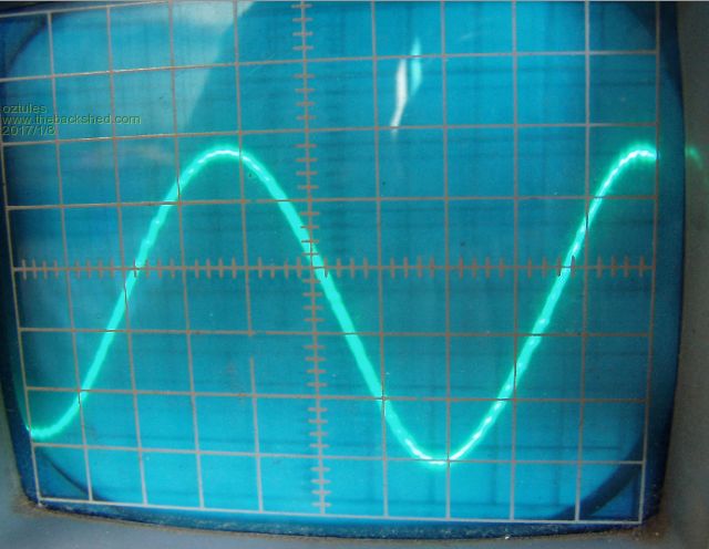 This is the same unit running 2500watts 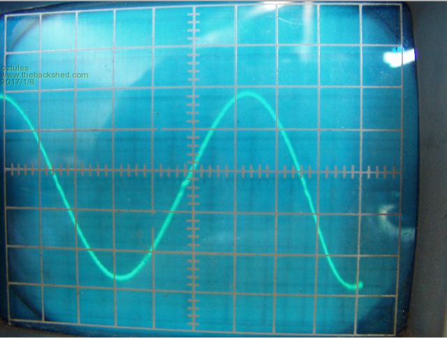 and this is the setup 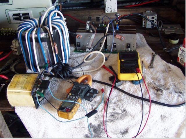 It is a bit tighter ( less fuzzy in the picture) than the idle one, so is actually improved slightly..... pretty much perfect.... with fine dimple. Now we run the next power board with the same control card. This is the idle pic 6 fets/leg to220 4110 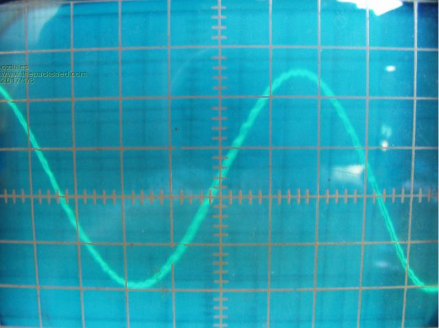 It is pretty close to the other one. This is the setup here: 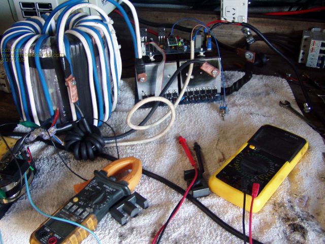 It gets interesting here. This is with 2500watts with the 6 fets. 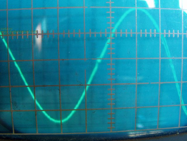 I didn't notice the little blip until I expanded it up.... but it is there. Now there is more to test, as this unit has not got the 4u7 filter cap on the little VFB transformer in the AC line, and I will test with the original setup later on..... but it looks like drive may be your problem.... for some reason, mine does not hardly suffer, but this unit is practically silent, and I have yet to find out why. The camera and I don't get along too well, and I have yet to find out how to speed up the shutter ... so there is multiple traces, which makes the line look very wide and strange, but in real life is a fairly good looking trace... other times it gets half or quarter of a trace  Even at 2500w, there is only the slightest hum..... wondering it it is the cap or not... but near tea time.....  ..............oztules Edit..... no. new setup with new control card WITH the 4u7.... no difference at all... nix. So it is not the cap, possibly the drive. Reversed the inductor from the 50hz zide to the 20khz side... no difference. Still no reason why this setup is so quiet compared to another one I have in front of me.... keep it may even be the transformer being slightly different.... who knows. Edit #2 yes there is a difference with and without the 4u7. With the ambient noise in the shed now much quieter, there is a very obvious difference between the two control cards with the 4u7 and without.... without is at least 12db quieter. There is noticable heating of the inductor ring... will have to check out which one caused it. Edit 3 Here is the blemish expanded greatly at 2500 watts.... not much but there. 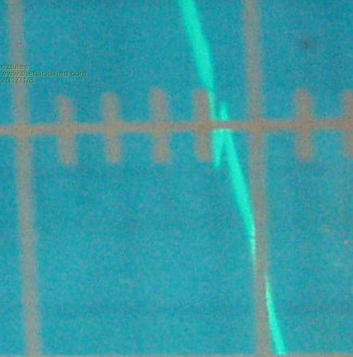 Village idiot...or... just another hack out of his depth |
||||
| Warpspeed Guru Joined: 09/08/2007 Location: AustraliaPosts: 4406 |
I tried it with the Trace Inverter after Warp mentioned how that type of inverter can easily go bi-directional. That did not go down well with the GTI and my PV charge controllers shut down and were screaming that I had a ground fault. O/k let me clarify this bidirectional stuff. If you have a very reactive load, either leading (capacitive) or lagging (inductive) the current can be badly out of phase with the voltage. This often happens with really nasty loads such as starting large motors, or starting up multiple fluorescent lights. The current flows out of the inverter on one quarter cycle, and flows back into the inverter on the following quarter cycle. Its never quite that bad, that would be zero power factor, but the out of phase energy can be substantial for short periods. Now what happens with a modified sinewave inverter, or any square wave inverter is the current through the mofet switches can reverse and feed power back into the dc bus. Its not a problem with reactive loads because the reflected energy must always be less than whatever power the inverter is putting out. So these types of inverters can be pretty robust with nasty loads. What you cannot safely do is connect the output to an external power source. All the energy you feed back into the inverter will go into the dc bus, (assuming the inverter is synced to the ac). That can cause bus dc runaway, because there is nothing to absorb that power, so the dc bus can quickly rise to destructive levels. Solar panels cannot absorb dc power, and neither can a dc to dc converter. A battery might, or it might not. I think that is what happened. dc bus runaway, and you had a solar over voltage alarm, or whatever it was. It may have gone way higher than 300v, enough to let the smoke out. Cheers, Tony. |
||||
oztules Guru Joined: 26/07/2007 Location: AustraliaPosts: 1686 |
Does not work fo rme Tony. The aerosharp is galvanically isolated, so no dc can feed back into it. The solar DC bus is what it is, and below the threshold for the aerosharp. The inverter has transformer coupling to the aerosharp, so once again, DC cannot transfer, and in fact the ac from the GTI appears as an AC signal on the fet outputs after going through the transformer. When they switch on, they synchronously rectify, but also as the fets turn off, they effectively short the inductor (the transformer) out, and this then behaves I think as a boost converter, which is why we can drive the battery to 70v or way more if we don't stop it....... from only a 28v rms transformer secondary. ( I think thats how they work) Something is wrong with the aerosharp I suspect, as it has never done that here out of thousands of hours, and over voltage shutdowns on a regular basis every day. I can drive many many KW and it runs cooler as a charger, than as an inverter. There are a few folks here that just use that system for most battery charging.... none have ever exhibited that behavior. It is generally rock solid.... something is wrong there. Selectronic techs said that their thing cant do that, but they do and have for the last few years. One has 4kw arrays connected to it all day every day... connected to it through aerosharp 1k5 units. Clockman in France does the same thing from memory. I'm just not understanding your DC bus theory perhaps. ..........oztules Village idiot...or... just another hack out of his depth |
||||