
|

|
Forum Index : Electronics : a new way to balance lithium ion battery
| Author | Message | ||||
| Warpspeed Guru Joined: 09/08/2007 Location: AustraliaPosts: 4406 |
I recently read an article on the internet about a guy that was planning to use some Nissan Leaf EV batteries for home power storage at high voltage. He wanted to keep the original Nissan factory BMS, and he was busy trying to reverse engineer it to discover exactly how it worked. Anyhow to cut a long story short, there is a 450 ohm surface mount discharge resistor across each cell, switched in and out by some mystery software. So to keep a 65Ah battery (similar in capacity to my own) requires only about 7mA to 8mA discharge to do the job. That does not sound like much, but over about five and a half days, its 1 whole amp hour. So amazingly only a very few milliamps can really accumulate over time. To duplicate that, I could switch in either a 250mA discharge resistor, or a 250mA current source, which will be connected to any individual cell only 1/30th of the time. Cheers, Tony. |
||||
| ESPcatman Newbie Joined: 12/06/2017 Location: New ZealandPosts: 2 |
Your cell balance idea works very well Klaus. I avoided damaging the relay by putting a pair of tiny 5v incandescent lamps in parallel and then put that in series with the super capacitors. Each lamp is rated for 60ma at 5 V. When the system is first started, the lamps glow each time a relay closes but after 20 minutes or so, the cells become perfectly balanced and the lamp glow is no longer visible. I pulse each relay on for 1 second then off for ten seconds then move on to the next relay. I am using an Arduino Uno to drive the 7 relays of my 7 cell, 53 Ah, 24v battery. I plan to use WiFi connected to the Arduino to report the charge status to my Android phone. You can see what I am up to at https://espcatblog.wordpress.com |
||||
| Tinker Guru Joined: 07/11/2007 Location: AustraliaPosts: 1904 |
ESPcatman, see my PM re that supercap balancing idea. But I see now that your cells are relatively small so it just 'might' work. Assuming when your relay is "on" you mean its connected to the corresponding cell, then I would suggest you change that time to 10 second 'on' and 0.5 second 'off'. Keep in mind that the charge transfers from a capacitor is exponential, the longer it is connected the more charge can be transferred, up to some practical time limit of course. You would also benefit from the relay contact method warpspeed posted, its brilliant as it nullifies any catastrophic effect if two relays pull in at the same time for some reason. I just did a 16 relay board with warpspeeds way of connecting the contacts and it works very well indeed. There is just one suitable relay I found at my local electronics shop (Altronics) that fitted my size, specs, pin arrangement and price category. The latter is quite important when 16 relays are involved. A bonus was that I could fit these relays on sockets (cheap SIL) so exchanging a faulty one takes only seconds. If anybody is interested I might write up this latest modification here. Klaus |
||||
| Warpspeed Guru Joined: 09/08/2007 Location: AustraliaPosts: 4406 |
Always interested in something a bit different Klaus. Cheers, Tony. |
||||
| Tinker Guru Joined: 07/11/2007 Location: AustraliaPosts: 1904 |
OK, time for an update to this project I started 6 years ago... A recap, the original idea using a super capacitor (I used 50 Farad) to shuffle charge from cell worked fine for *new* cells. I started with an 8 cell 24 Volt/ 200Ah lithium battery bank. This ran for 3 years and over time I noticed the capacitor method of balancing was struggling a bit. There were also problems with relay contacts, I turned off the balancing overnight to save contact wear but this allowed the supercap to discharge and its inrush current is capable to weld relay contacts when the balancing cycle restarted with battery charge coming in from the solar panels. Anyway, lots of tinkering with different relays and even with driving them by a program that was seeking the cell with the highest charge and then that with the lowest charge, followed by several 'charge dumping' cycles since one can only 'dump' a small amount at a time due the small (mV) difference in cell potential. Here is a pic of a box full of discharged experimental home etched boards: 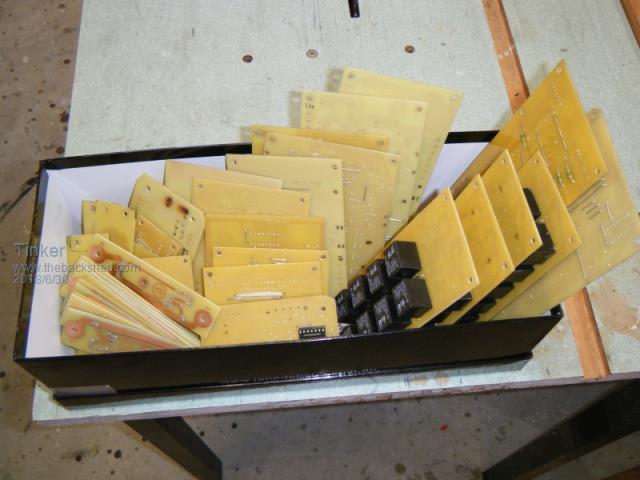 After 3 years I upgraded to a 48V battery bank which required a new approach to cell balancing. Here is a pic of an early version of my balancer: 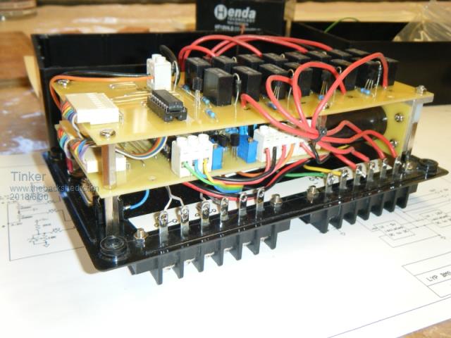 Instead of an exponential decaying charge from the supercap transfer I replaced that cap with a fixed voltage isolated power supply. This, set to just below maximum allowable cell voltage, transfers charge which is tailored, depending on the connected cell, automatically and for the full connect time of each cell. Quite a lot more charge transfer can happen now even though I had gone back to the sequential stepping through the cells method. The hi/lo seeking method takes way too long with 16 cells... So, this is what balanced my battery bank for the last 3 years: 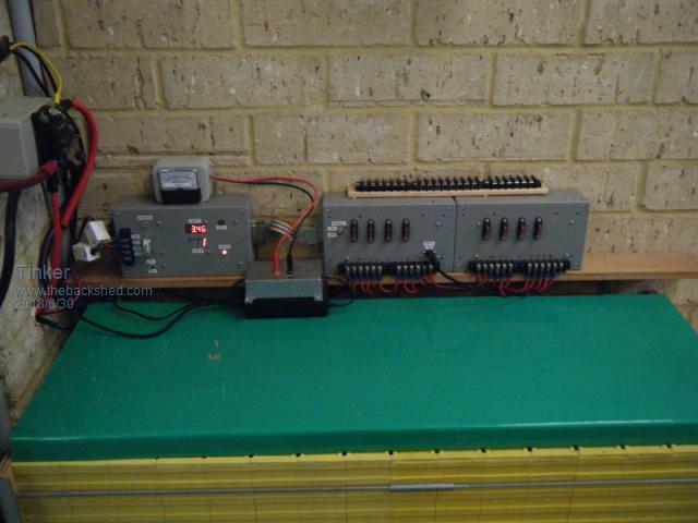 It worked fine but has half a dozen PCB's spread over 3 enclosures. Time to find a simpler way  . .Using a made in China double sided board I could squeeze all 16 relays on it. Those relays were a good find, passing my size, price and contact/pin arrangement criteria. Here is what it looks like: 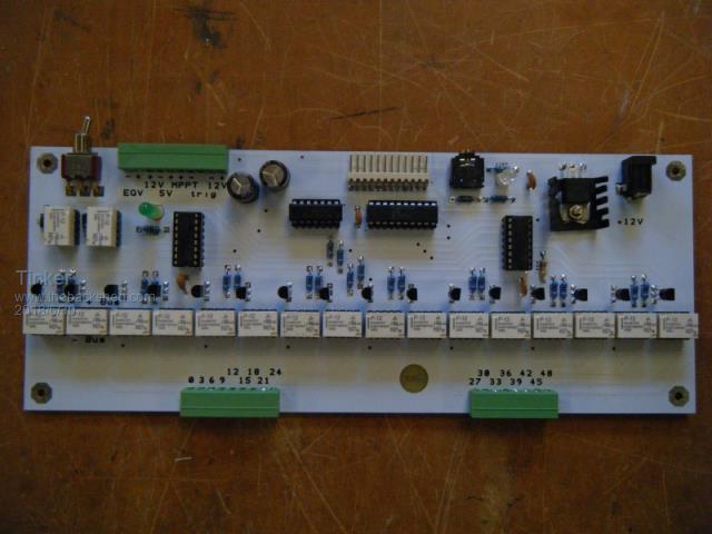 Its driven by the same simple picaxe micro I used for my earlier versions, the relay on/off times etc being easily changed to suit. I made a test rig which passes a few milli Amps via incandescent bulbs through the contacts, far less disastrous if something were wrong than when the relays are connected across 200Ah cells. The bulbs light up as the sequence closes each relay in turn and can be observed for sufficient 'dead' time between steps. 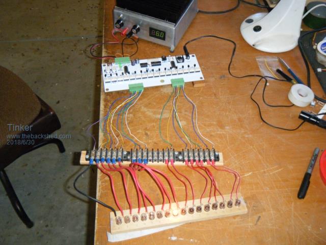 Here it is in operation: 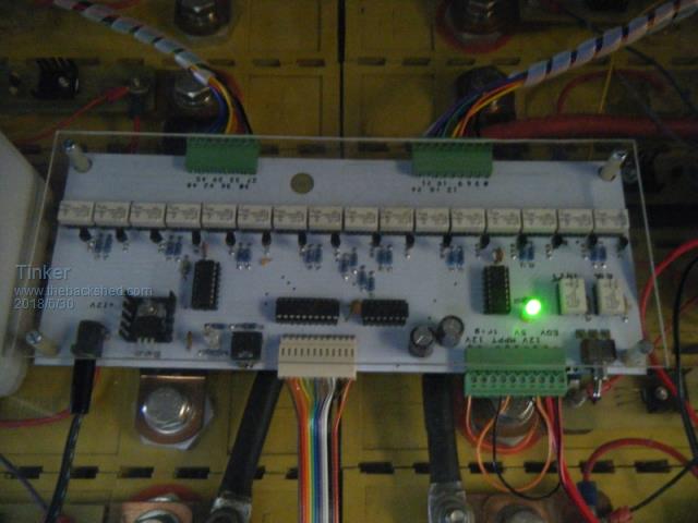 There is a LED display that shows each cell Voltage and cell number as the program steps on. Battery voltage and current is also displayed here. Another enclosure with a series analog Ammeter shows the particular charge rate for that cell. Observing this I can easily see if all is well. That output could be logged but Its not done yet. 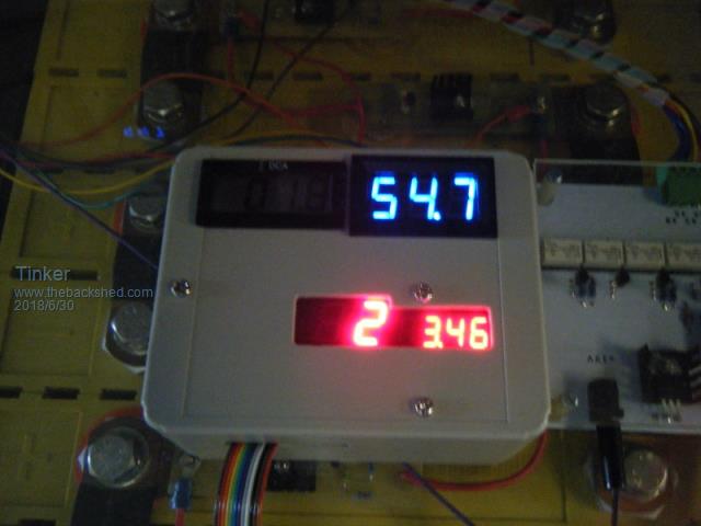 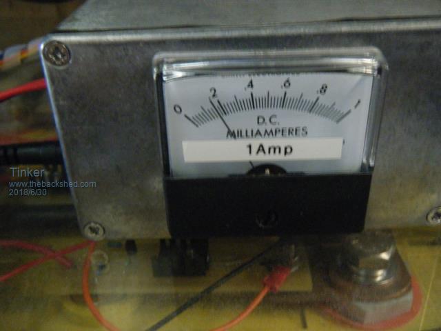 Lastly, this type of balancing does not prevent overcharging the cells so another kind of cell balance (shunt regulator) is employed for that. From my observations for new cells, a shunt regulator across each cells might have very little work to do if the charging voltages are set right. However, I have found my 6 year old cells definitely require this, they go out of balance very quickly otherwise as I found out when removing them while re arranging some connections and leaving the shunt regulator off for a few days. This is what they look like, one across each cell: 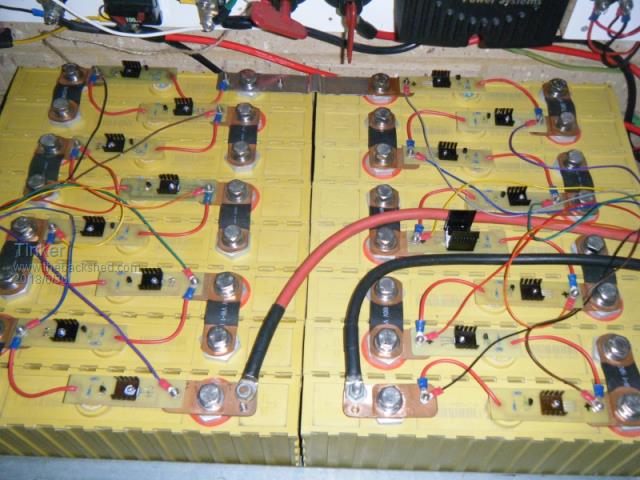 Close inspection may notice one cell shunt reg. has a bigger heat sink, this cell had drifted way too high during the absorption cycle and required severe charge dumping for a while. Its now back in line with the others. So, how does it all work? Below are the schematics for the relay and control board, there is another for the display which I can post if anybody is interested. 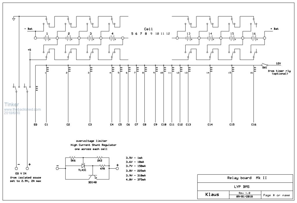 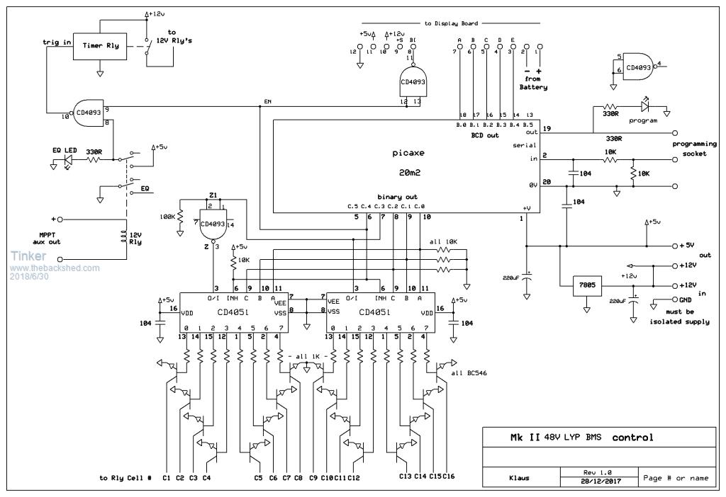 My thanks go to warpspeed for suggesting the relay contact arrangement, it works a treat  . .Also, as I had to order a minimum quantity of PCB boards I have now 2 surplus boards, available at cost plus postage. Klaus |
||||
| ESPcatman Newbie Joined: 12/06/2017 Location: New ZealandPosts: 2 |
I did it much more simply. I connected the super capacitor across the first cell and waited for 1 second. Then I opened that relay, wait for 10 seconds and closed the next one that placed the capacitor across the next cell for 1 second. I just keep doing that over and over for ever. Remember that I have a tiny incandescent lamp (actually two in parallel) in series with the capacitor to limit the current. Not also that it has been suggested that my small cells are so nearly equal that they don't require much balancing. Your idea of a more sophisticated algorithm is good. I thought maybe I would measure all the cells and then swap the capacitor back and forth between the lowest cell and the highest cell 4 or five times. I would then repeat the process over and over. There are lots of possible algorithms you could try. |
||||
| Warpspeed Guru Joined: 09/08/2007 Location: AustraliaPosts: 4406 |
Welcome to the Forum ESPcatman. Klaus had a system very similar to yours at one stage. I called it a "capacitor hopper". And it does work, but the amount of charge transferred is not very high. If your cells are either very large, or very old it may struggle, but for a very small system it should work. My first system used a relay mounted on top of each cell with the contacts connected the same way Klaus has connected his. The relay contacts are daisy chained with short links between the cell circuit boards using spade connectors, so at the end of the chain I had a pair of connections that could be connected to either a cell charger, a cell discharger, or for direct cell voltage measurement, all under software control. These relay contacts switched power perfectly well, but were a total disaster when trying to accurately measure individual cell voltage at high impedance. It may have worked with much higher quality relays such as mercury wetted relays, or vacuum relays, but the cost of the relays made the whole relay idea impractical for what I really wished to do. Ordinary electromechanical relays will work perfectly well for switching power. But I wanted to use this for accurate reliable long term control and monitoring, so had to think of a better way to consistently monitor cell voltages. Cell voltage monitoring is my very first priority, cell balancing comes a distant second. The next attempt replaced the mechanical relays with solid state relays LAA127. http://www.ixysic.com/home/pdfs.nsf/www/LAA127.pdf/$file/LAA127.pdf This is all now working extremely well for monitoring cell voltages, and the LAA127 can be 100% protected with a 100mA fast blow fuse if two different cell relays turn on together (with a 100v battery) in the event of a software crash. This is important, because if one mosfet switch fails, it will blow up all the others as they progressively turn on, causing a cascading failure of the whole lot. These switches are very slow to turn off, so there needs to be a lot of dead time in software timing loops to prevent switch overlap. If the software ever derails, the fuses can put on a spectacular fireworks light show display. Fuses are cheap and easy to replace, so its not a big deal. I have blown dozens of fuses due to idiot software programming, but never an LAA127 so this protection can definitely be relied upon and is highly recommended, especially for higher voltage batteries. Unfortunately, because of the combined up to 20 ohms of series "on" resistance, this solid state relay system could only be used for voltage monitoring, and not for transferring worthwhile power. But it does make an absolute ripper of a cell voltage monitor. Version three has an on board current discharger almost identical to Klaus's using a TL431 and BD140. My 50Ah cells are very small, so I limited the discharge current with a 27 ohm 1 watt resistor, and no heat sinking is required for the BD140 This works very well and is what I now have. 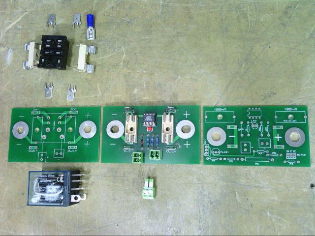 Cheers, Tony. |
||||
| wiseguy Guru Joined: 21/06/2018 Location: AustraliaPosts: 1156 |
First let me congratulate all who contributed to this post on balancing cells, a combination of some great ideas, problems & solutions, it all got my grey matter going - have to give some credit to Klaus for starting the thread and the concept of shifting charge efficiently. I have an idea that may not be popular to start with, but I believe it is an ideal solution with no wasted power (apart from a small magnetizing current) and perfect cell voltage balance and able to balance strings with serious balancing currents if required, whilst being charged at high series string currents and all totally galvanically isolated from each other in the string and the outside world - sounds too good to be true. I am a switchmode guy and have been for ~ 30 years I always use synchronous rectification and usually use a topology of current fed bridge converters. I have had heaps of fun (and not so much fun...) learning and experimenting with these things over the years. There is such a thing as a DC transformer (bear with me - this is not snake oil) which has some amazing qualities. If you synchronously drive input fets and output fets all optically isolated, then you can transfer a heap of current from a to b or b to a - whichever is higher determines current flow direction. I am sure some of the astute guys here are already seeing where this is going. If I put multiple isolated 1:1 windings on the transformer (1 winding for each string) and a small series resistance say 0R1 for an example in series with each input (or is that output - you tell me which one is higher and Ill tell you which it is....) then we limit balance current to a simple ohms law calculation - determine best and worst battery voltage difference and grab a calculator. If we use a two battery case for simplicity & a difference of .2 of a volt between the cells the balance charge current flow to the lower battery will be 1A. With multiple strings some will be higher some lower but they will all sort themselves to exactly equal voltages in a relatively short time by transferring charge efficiently(how much balance current do you want?? - just use resistors smaller than 0R1). I propose a drive signal of 50/50 duty cycle at 25 - 50 kHz (think UCC2808-2 or UCC3808-2 running open loop)and 2 volts per turn is an excellent starting point (yep 2 turns each or 4 turns CT if you want to minimise the quantity of FETS). All batteries galvanically isolated from each other and the outside world, no contacts to deteriorate or fail and pretty low cost to build. 2 Fets (1-2$) 1 fast dual opto coupler (HCPL2611?) ($2.50), 2 fet drivers $1 (ZXGD3009E6TA - thanks Solar Mike great parts!), 2 foot of 1mm wire and a few ancilliary bits per Cell. One extra winding with synchronous fets and you have a DVM or logger feed thats conveniently isolated from everything & will tell you the exact balance voltage. The whole thing can be commanded to operate on or off by enabling the opto drive currents. Put a 1 - 10A fuse in series with each connection and simple LED resistor combination to show you of a fault if the fuse opens (or and connect some optos as well for a common isolated alarm output that warns of a faulty Cell balancer. This might sound a little scary to mere mortals but doing this is a cinch compared to a 2+kW inverter !! If we looked at 20 batteries half overcharged by 0.1V and the other half undercharged by .1 volt we are transforming ~ 10 amps at say 3.5 volts WOW 35 watts!! If you could fit all the windings on it, an ETD 34 would be ample. If you run out of room just make a second unit identical to the first and connect more batteries just use the drive signals from board 1 to drive more boards. I am busy with some other projects ATM but if you all give up too easy I will come up with a schematic & post it in due course. I am convinced this is the ultimate balancer for Automotive EV (or motor home) or serious grid/solar/wind installations. I invite comments positive or negative - this may be the beginning of something.... If at first you dont succeed, I suggest you avoid sky diving.... Cheers Mike |
||||
| Warpspeed Guru Joined: 09/08/2007 Location: AustraliaPosts: 4406 |
I am a hard core switchmode nut myself, so understand perfectly where you are coming from. I had very seriously considered a similar concept at one stage. As I have thirty rather small cells, it would require a lot of parts to have built an experimental prototype to test. But if I had fewer and much larger cells I would definitely have had a go at something like this. I may actually try it one day, but there are too many other things going on right now. From what I have read, high current active cell balancing is not really required unless the battery is being worked very hard indeed, or it is really old. So I put the whole idea on the back burner. I visualized this as having continuously driven push pull mosfets and a small isolation transformer at each battery cell, feeding into a common bi directional ac "power" bus. It would require a second "synchronization" bus continuously driven from an external source to provide identical drive waveforms so everything switched synchronously. One limitation is the cell voltage might be as low as 3.0v or even less so at the very least a capacitor charge pump would be required to generate a usable gate drive voltage to power up a pair of opto isolated gate drivers. A simpler but slightly more expensive option would be a pulse transformer to drive the mosfet gates directly from the synchronization bus. There is no reason why it has to be driven at an insanely high frequency, a quite low switching frequency would be far more manageable. Something will be needed to limit the maximum current flow under abnormal conditions, but a simple fuse might be sufficient. Definitely a very interesting concept, especially for the low voltage big battery guys where there are fewer cells and greater power needs to be shuffled around. Cheers, Tony. |
||||
| wiseguy Guru Joined: 21/06/2018 Location: AustraliaPosts: 1156 |
You are almost there but I am not sure you have grasped the total simplicity. Each winding and pair of FETs becomes a master there is no input FETs output FETs and bussing required as there is no common bus just a common core. Correct with the master drive wave-forms for each pair of Fets. This may need a little work and experimentation but imagine using logic FETs as we have individual 3+ volts isolated supplies (maybe all 200A of it) per balancer. Add a couple of caps and diodes to the winding and scavenge a simple voltage doubler for extra gate drive voltage (think diode or). (oops didnt read your reply correctly you suggested similar) I have a complete bells and whistles concept in mind such as traffic lights for each cell for charge/balance/discharge or upmarket isolated 2Ch A/D to monitor individual cell volts and current and direction, ability to isolate a single or any or all balancers with another opto and FET. I get it about the balancing current required but you can do it as fast or slow as you want - the ability to do it real fast is there (you almost got it for free) if you want it - no other method so far has got anything like this ability. If at first you dont succeed, I suggest you avoid sky diving.... Cheers Mike |
||||
| Warpspeed Guru Joined: 09/08/2007 Location: AustraliaPosts: 4406 |
A single transformer becomes difficult. How would I wind something with the thirty isolated windings I would require, and have very low leakage inductance ? It would be a rats nest of wiring. A bus system with individual transformers would be far neater, and modular. I agree that a single transformer would be ideal for say four cells and 12v, but beyond that it starts to get a lot more difficult to do in practice. Much better to have a bunch of identical circuit boards each bolted onto its own cell, that are just all linked together IMHO. Cheers, Tony. |
||||
| Solar Mike Guru Joined: 08/02/2015 Location: New ZealandPosts: 1138 |
I like what you have done there Tinker, its great that you have engineered a solution that works well. My bank is 16s x 800AH Lifepo4 cells, they only currently get manually balanced every 6 months or so. When each cell voltage is in the upper voltage rise knee around the 3.45 to 3.5 is the time for any balancing to occur, and must be done with higher currents 10-15 amps or more to have any effect. The idea of having 16 lots of cell discharge resistors @10 amps isn't where I want to go. My thoughts were to use a single 40 watt mosfet flyback booster attached to every cell and have it discharge into the whole bank buss (50v) when that cell gets to the high point of its charge, this will automatically boost lower voltage cells and not waste too much power as heat. It can still be autonomous and turned on by a TL431 voltage reference on each flyback board. Wiseguy's idea seems better in this respect however may be more complicated, a simple circuit to help visualize the idea would be nice... Cheers Mike |
||||
| wiseguy Guru Joined: 21/06/2018 Location: AustraliaPosts: 1156 |
This could be done in a lot of different ways, your way would also work but at a much greater parts count & complexity - I was trying to simplify & minimise the parts count. I did say in my first post just gang another board with the same drive signals (+ another transformer and circuitry). I dont see the leakage inductance being an issue, will there be some - sure, does it matter, not really IMO. As there are only 2 turns per bridge or 4 turns CT per push pull I think they would all fit in the former - you could even use kynar wire or similar for lower balance currents. Cut 2 formers (bobbins) in half (vertical or horizontal types) and join the (right) 2 halves together & have 4 sets of pins instead of 2 and add another PCB to the other side/end. After seeing what these guys do with toroids and damn thick copper a 2/4 turn winding on a lightweight former is childs play. By the way heatsinks for the FETs are not required SMD devices would work fine at these power levels. The original post was to get others grey matter going to consider a new concept & work on solutions as required. Lets not just identify challenges only but also think laterally of solutions to overcome them. If at first you dont succeed, I suggest you avoid sky diving.... Cheers Mike |
||||
| Warpspeed Guru Joined: 09/08/2007 Location: AustraliaPosts: 4406 |
Yes, Klaus deserves a very great deal of credit for all the work he has put into this topic and freely shared with us all. To those out there still scratching their heads... This is not pie in the sky stuff, its a definite proven technique. The idea is to have a single transformer with each cell having a push pull driver with its own winding on a common core. If the "A" and "B" mosfets are all driven together alternately with identical drive waveforms, power will flow between the higher voltage cells to the lower voltage cells. The cells remain individually fully dc isolated, but the cell voltages equalize just as if they were hard wired in parallel with a very low ohmic resistance. This is the general idea: 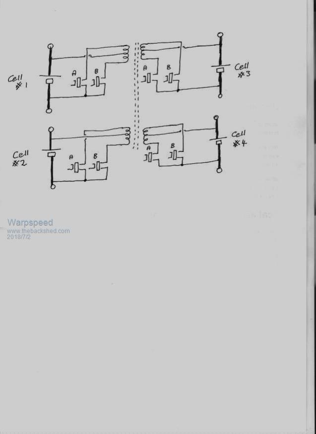 This shows four fully isolated cells coupled together with a single transformer that has four windings. Very neat and efficient where there are few cells. An arguably better way, especially where there are a very large number of cells, is to give each cell its own small transformer, and couple all these individual transformers together onto a common bus. The operating principle is identical, its just a physically different way of going about the same thing. 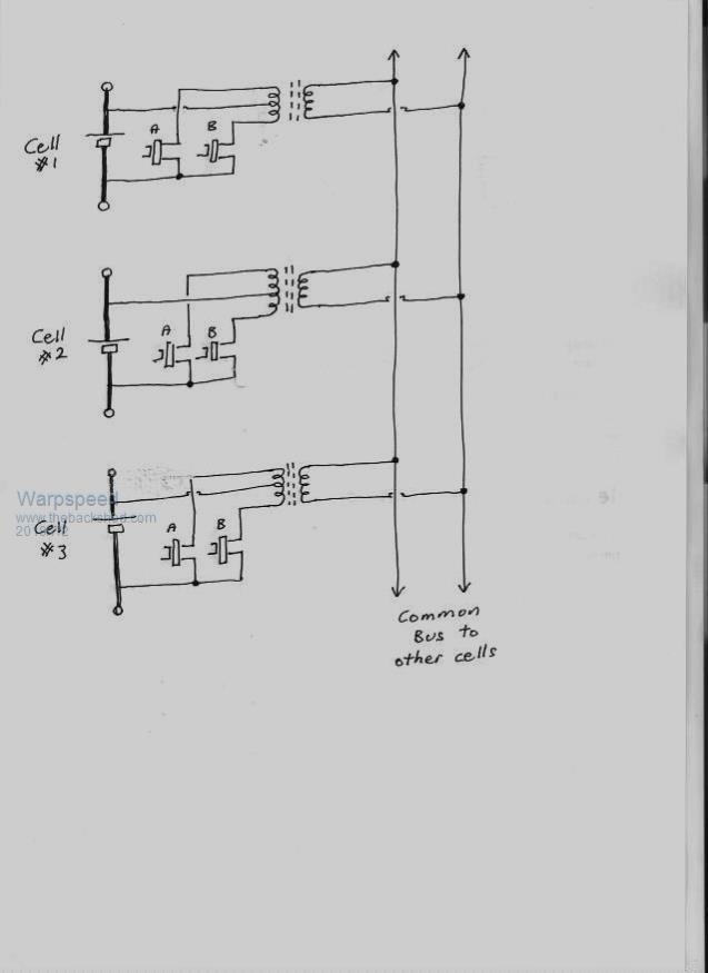 Cheers, Tony. |
||||
| Solar Mike Guru Joined: 08/02/2015 Location: New ZealandPosts: 1138 |
The individual transformer\cell way is going to reduce he amount of RFI by a huge amount as the cables are shorter. Its already bad enough around here at night with the cheap Chinese led light bulbs filling the spectrum up with hash and affecting the radio. How do the car manufactures do this, they have spent millions on research and surely would have the best solution. |
||||
| Warpspeed Guru Joined: 09/08/2007 Location: AustraliaPosts: 4406 |
The Nissan Leaf uses (I think) 65 Ah cells, not terribly large. They switch a 420 ohm surface mount resistor across each cell under software control. This works 24 hours per day. It does not sound like much, but over weeks, months, and years those milliamps must all add up. Cheers, Tony. |
||||
| wiseguy Guru Joined: 21/06/2018 Location: AustraliaPosts: 1156 |
I forgot about pencil and paper....I was in the process of doing such a sketch on cad - thanks Warp See - you developed an AC bus which would work and has way fewer parts than a DC Bus. If we use a double ended ETD39 core bobbin we could have 32 pins, so with 1 flying lead we have 11 CT windings. Thus we can balance 10 Cells and could have an extra DC Rectified Bus that we can couple likewise to the next Board of 10 Cells. Two transformers & 20 cells being balanced. Transporting DC would mean we can use common mode chokes, ferrite tubes etc to keep Solar Mikes happy - (transporting AC squarewaves that have harmonics that stretch from Dc to Light (well nearly) on long wires) is environmentally unfriendly for emi. I am not trying to drive a particular solution just putting stuff out there to consider. If at first you dont succeed, I suggest you avoid sky diving.... Cheers Mike |
||||
| Solar Mike Guru Joined: 08/02/2015 Location: New ZealandPosts: 1138 |
Considering that any measurable voltage differences between cells are only apparent during the cell discharge or top of charge end points, and the time duration of each may be less than an hour, a 420 ohm resistor seems insufficient. They must use individual cell coulomb counters to work out how long to leave any individual cell discharging. This means a complex cpu solution is required, don't want to go that way either... |
||||
| wiseguy Guru Joined: 21/06/2018 Location: AustraliaPosts: 1156 |
Before too much time is devoted to heading in a particular direction for this discussion I think we need a spec of some sort. In a small or large LiPo string set up, what is the maximum/minimum balance currents that are needed ? That will help shape the right solution. Perhaps individual small transformers and SMD devices and a DC bus is still the way to go for low power (sub 100mA ?) we just bus the opto drives and Dc between boards. However this is leaning to a commercial solution as soldering SMDs with ailing eyesight (and patience) is not my idea of a fun evening..... rewinding a big toroid is almost in the same league. If at first you dont succeed, I suggest you avoid sky diving.... Cheers Mike |
||||
| Warpspeed Guru Joined: 09/08/2007 Location: AustraliaPosts: 4406 |
Mike, Don't know how the software works Mike, but it probably works out what needs to be done during charge/discharge as you suggest. Then nibbles away at the problem very long term and very slowly. There are several separate battery modules, and each has its own microprocessor and BMS, all linked to the other modules and to the whole overall vehicle management system by serial data links. A real dog's breakfast, and hackers dream. Wiseguy, Many possible ways to go about it. Might even be possible to pass a cable bundle through multiple high permeability toroids so that only one turn is required to couple everything together, current transformer style. EMI could be eased by slowing the whole mess right down. Just because its a switching power supply it does not have to operate at 500+Khz. Only half joking, but why not switch at 500 Hz ? I still like the idea of pulse transformers driving the gates, and individual power transformers for each cell on identical circuit boards. That is a lot of transformers, but apart from the actual mosfets, there would not be much else required. Cheers, Tony. |
||||