
|

|
Forum Index : Microcontroller and PC projects : PicoMite V6.00.00 release candidates - all versions
| Author | Message | ||||
| guma1975 Newbie Joined: 13/01/2023 Location: PolandPosts: 7 |
list ' err for next ? 'sprawdzmy.... For r=0 To 15 Print r Next r Print "end of r=15" Print "r=";r > run 0 1 2 3 4 5 6 7 8 9 10 11 12 13 14 15 end of r=15 r= 16 > Is this correct?? r should be 15 not 16? ---------------------------------------- MODE 4 'mode 4 for optior resolution 640!!! HDMI !!! '320x240 32k colour x=0 y=0 szer=179 dz=5 For g=0 To 255 Line (x+g)/dz,y,(x+g)/dz,y+szer,,RGB(255,g,b):Next g g=255 ' ======= ERR r=256? ====== For r=0 To 255 Line (x+r+256)/dz,y,(x+r+256)/dz,y+szer,,RGB(255-r,g,b):Next r r=255 For b=0 To 255 Line (x+b+512)/dz,y,(x+b+512)/dz,y+szer,,RGB(0,g,b):Next b b=255 For g=0 To 255 Line (x+g+768)/dz,y,(x+g+768)/dz,y+szer,,RGB(0,255-g,b):Next g g=255 For r=0 To 255 Line (x+r+1024)/dz,y,(x+r+1024)/dz,y+szer,,RGB(r,0,b):Next r r=255 For b=0 To 255 Line (x+b+1280)/dz,y,(x+b+1280)/dz,y+szer,,RGB(r,0,255-b):Next b b=255 Print @(90,100,1)"HDMI MODE=4 320x240 32k colour" Print @(0,190,0) 'Save image "HDMI_MODE4_320x240x32k_colour" Option list here is an example of a program drawing a rainbow in hdmi 640 mode 4 ... where I had to decrease the variable after the end of "FOR" Edited 2024-10-11 05:06 by guma1975 |
||||
| Hans Senior Member Joined: 18/10/2022 Location: CanadaPosts: 116 |
Hi All; I have tried 6.0RC6 on a number of my PICO builds and have not had any problems except when I tried it out on the RP2040-Geek. It worked properly on 5.9.0RC5 as in the screen shorts below; 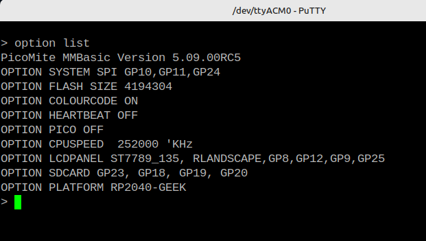 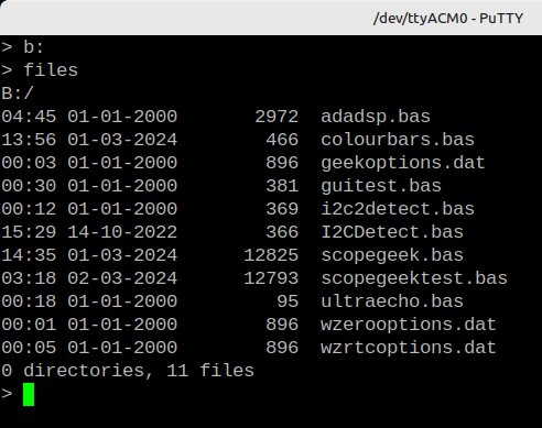 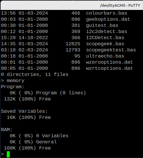 Cleared with clear_flash.uf2, Loaded 6.0RC6 shown with memory command, this shows normal at first. 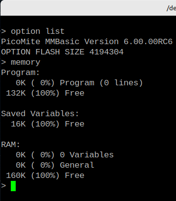 Executed Option Reset RP2040-Geek 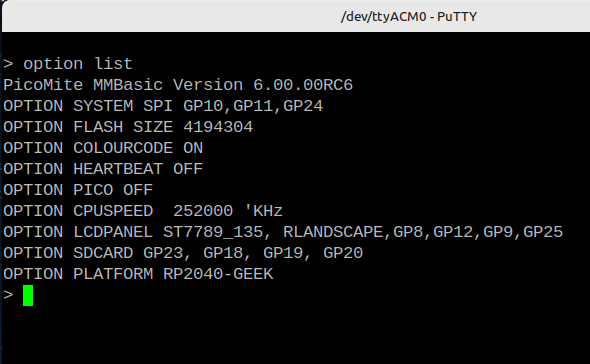 Executed B:[ENTER], note memory still looks normal 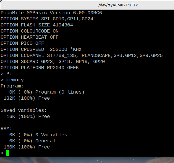 After executing the FILES command I got a drive error and the memory usage changed. 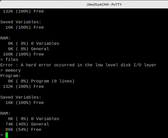 It would not read any sd cards that could be read on other PICO's. Reading the A: was not a problem. After I reloaded 5.9.0RC5 I was able to read the same SDCard again. I have done this exercise twice now with the same results. If you need more information please ask. Thanks, Hans ...  |
||||
| guma1975 Newbie Joined: 13/01/2023 Location: PolandPosts: 7 |
But I'm stupid... Sorry for this post for next.... this is normal behavior..... it exits the loop when the condition is not met and will be one bigger yh.... sorry. |
||||
| matherp Guru Joined: 11/12/2012 Location: United KingdomPosts: 9130 |
This is the way MMBasic works. In all versions (just tested a MM2) the loop terminates with the loop counter at 1 greater than the test value. I have made a change that should have already been in there ( I thought it was). The SD card is bitbanged to initialise it as the SPI baudrate needed is less than that possible with H/W SPI. Once initialised you can up the baudrate. All cards are supposed to support 12Mbit SPI. Previously, by error, the firmware continued to use bitbanging after the rate change. The firmware now switches to SPI at 12Mbit. I've tested this on multiple boards and with different cards and it gives no problems. The fact that the RP2040-Geek doesn't work suggests they have something odd about their SDcard implementation or their wiring of the sdcard relative to the display. Sorry but I don't intend to revert unless there are other reports of issues. |
||||
| Volhout Guru Joined: 05/03/2018 Location: NetherlandsPosts: 4250 |
Hi Peter, On the GEEK the SD card is SPI1 (GPIO18,19,20). And SPI2 to the display is on GPIO10,11 is MOSI only (MISO is routed to GP24, that is NC). So they are different SPI busses (unlike most ILI9341 alike systems). Maybe that is part of the problem. There is nothing odd in the GEEK circuit. See attached. Just pin-pin connections. RP2040-GEEK-Schematic.zip Volhout Hans: if this can't be fixed then stay at 5.09.00. At this moment there are no changes in 6.0.0 that are important for GEEK applications. This may be different in the future, but main focus at the moment is 2350 features, and GEEK is 2040. But even if it is fixed, when SPI1 is in use for SD card now, you cannot use it anymore for GP2/GP3/GP4. For me(personally) that is what I use to experiment on with GEEK. Edited 2024-10-11 18:57 by Volhout PicomiteVGA PETSCII ROBOTS |
||||
| matherp Guru Joined: 11/12/2012 Location: United KingdomPosts: 9130 |
Oh, I'd forgotten all about that - another special case needed Try the attached PicoMite (2).zip Edited 2024-10-11 18:59 by matherp |
||||
| electricat Senior Member Joined: 30/11/2020 Location: LithuaniaPosts: 161 |
Peter, Finnaly I found source of my problems !! Sub PrintTime() Colour c(14),c(1) Print @(600,0);Mid$(Time$,1,5); Colour c(15),c(0) End Sub So case closed. Bug in my head  |
||||
| matherp Guru Joined: 11/12/2012 Location: United KingdomPosts: 9130 |
 |
||||
| Mixtel90 Guru Joined: 05/10/2019 Location: United KingdomPosts: 6798 |
I assume, Peter, that when a SD card is used with an assortment of pins rather than on a hardware SPI port it will continue to be bitbanged at the lower speed as before? That would make sense. Mick Zilog Inside! nascom.info for Nascom & Gemini Preliminary MMBasic docs & my PCB designs |
||||
| electricat Senior Member Joined: 30/11/2020 Location: LithuaniaPosts: 161 |
Peter, Still I might be missed something to read, But why in monochrome mode it is alowed to use colour command at all as if it was used somehow like TILES ?? Working example MODE 1 Print "No color";: Color RGB(RED), RGB(YELLOW) : Print "Now with colour" It is comfort way, sure. But it raises problems with TILE as it seems Edited 2024-10-11 19:57 by electricat |
||||
| matherp Guru Joined: 11/12/2012 Location: United KingdomPosts: 9130 |
Yes, of course. The issue was the stupid design of the geek which uses a different set of SPI pins for the display than for the sdcard Colour sets the default foreground and background colours so, to the extent that text aligns with the tiles, the firmware uses these colours when outputting text with a print command and a text command unless it specifically overrides the defaults |
||||
| matherp Guru Joined: 11/12/2012 Location: United KingdomPosts: 9130 |
V6.00.00RC7 Restores correct audio buffer size Should fix an issue when the SDcard is not on the same SPI channel as the system spi PicoMiteRP2040V6.00.00RC7.zip PicoMiteRP2350V6.00.00RC7.zip |
||||
| Martin H. Guru Joined: 04/06/2022 Location: GermanyPosts: 1114 |
Peter FLAC files can be played as usual, thanks for fixing it. what still happens is that when using layers after pressing ctrl&c I get no cursor displayed, so far I could create an error by typing letters and the output appeared normally again. This no longer works, the output (EDIT etc,) only appears in the terminal but not on the screen. even a restart does not change this. I was only able to get the console back on the screen with flash_nuke.uf2 edit: after flashing the firmware PicoMiteVGA MMBasic Version 6.00.00RC7 again, I get my console displayed again after generating an error message Cheers Martin Edited 2024-10-11 21:17 by Martin H. 'no comment |
||||
| homa Guru Joined: 05/11/2021 Location: GermanyPosts: 351 |
Circle MM.HRes/2,MM.VRes/2,20,1,1,RGB(yellow),1 The circle remains unfilled ?!? Solution: Circle MM.HRes/2,MM.VRes/2,20,1,1,RGB(yellow),RGB(yellow) Sorry. Edited 2024-10-12 00:27 by homa |
||||
| matherp Guru Joined: 11/12/2012 Location: United KingdomPosts: 9130 |
It would be helpful if reports included which version you are using including which chip and any options. Are you sure it isn't filled with black which is what you have asked for? Martin: please run the following and stop it with ctrl-C. I see the normal command prompt and any subsequent typing with no issues MODE 2 FRAMEBUFFER layer FRAMEBUFFER layer top FRAMEBUFFER write T 'Box i,MM.VRes\6*2,MM.HRes\4,MM.VRes\3,10,RGB(red),RGB(green) FRAMEBUFFER write l 'Circle MM.HRes\2,MM.VRes\2,MM.HRes\4,10,1,RGB(blue),RGB(yellow) 'Text MM.HRes\2,MM.VRes\2,"MIDDLE",CM,,3,RGB(CYAN),-1 d=1 i=0 rr=0 x=Sin(Rad(0))*40 y=Cos(Rad(0))*40 Do FRAMEBUFFER write n r = Rnd * 255 g = Rnd * 255 b = Rnd * 255 Circle Rnd * MM.HRes, Rnd * MM.VRes, Rnd * MM.HRes/7,,, 0, RGB(r,g,b) Inc rr,3 xl=x yl=y x=Sin(Rad(rr))*40 y=-Cos(Rad(rr))*40 FRAMEBUFFER wait FRAMEBUFFER write l Circle MM.HRes\2+xl,MM.VRes\2+yl,MM.HRes\6,0,1,0,0 Circle MM.HRes\2+x,MM.VRes\2+y,MM.HRes\6,10,1,RGB(blue),RGB(yellow) Text MM.HRes\2+x,MM.VRes\2+y,"MIDDLE",CM,,2,RGB(CYAN),-1 FRAMEBUFFER write t Box i,MM.VRes\6*2,MM.HRes\4,MM.VRes\3,0,0,0 Inc i,d Box i,MM.VRes\6*2,MM.HRes\4,MM.VRes\3,10,RGB(red),RGB(green) Text i+MM.HRes/8,MM.VRes\2,"TOP",CM,,3,RGB(magenta),RGB(green) If i>=MM.HRes/4*3 Then d=-1 If i=0 Then d=1 Loop Edited 2024-10-12 03:41 by matherp |
||||
| Hans Senior Member Joined: 18/10/2022 Location: CanadaPosts: 116 |
@Peter/@Harm Thank you both!  Both the fix and RC7 work just fine on the Geek.  Hans ...  |
||||
| JanVolk Senior Member Joined: 28/01/2023 Location: NetherlandsPosts: 145 |
Peter, I finally figured out the reset issue in my previous comment. "Did some tests with RP2040 Unstable after Version 6.00.00RC3 regarding Reset and USB connection. After one or two resets, the USB connection is disconnected and must be reconnected manually." The cause of the problem is TeraTerm. Went back to version 4.106 and the reset problem no longer occurs. So versions after 6.00.00RC3 through 6.00.00RC7 now work correctly. Jan. |
||||
| Mixtel90 Guru Joined: 05/10/2019 Location: United KingdomPosts: 6798 |
An alternative terminal emulator to try is YAT (Yet Another Terminal). It's rather nice and has a lot of options. Mick Zilog Inside! nascom.info for Nascom & Gemini Preliminary MMBasic docs & my PCB designs |
||||
| Martin H. Guru Joined: 04/06/2022 Location: GermanyPosts: 1114 |
Good morning Peter I have finally found the culprit..  For debugging purposes, I usually use the following Line Option lcdpanel noconsole at the beginning of the program, To output events or variables in the terminal.that happens almost "automatically", so I didn't think about it anymore In the old versions (5.x), this was reset after the program was interrupted (ctrl/C). this no longer happens, so the cursor etc. only appears back again when I enter Option lcdpanel console I can't tell if this is a bug or a feature.It can also be useful if you want to save a screenshot of (just) layer N, for example.  Cheers Martin Edited 2024-10-12 15:08 by Martin H. 'no comment |
||||
| matherp Guru Joined: 11/12/2012 Location: United KingdomPosts: 9130 |
Option lcdpanel console/noconsole should not be used in a program and I will block this. It is deprecated in this usage. Use OPTION CONSOLE SERIAL/SCREEN/BOTH to control output from PRINT statements. This is a temporary option that is reset whenever a program terminates. In the next release I'll also add OPTION CONSOLE NONE as an option and in this case it will be reset by an error so error output isn't missed. |
||||