|

|
Forum Index : Electronics : Inverter building using Wiseguys Power board and the Nano drive board
| Author | Message | ||||
| KeepIS Guru Joined: 13/10/2014 Location: AustraliaPosts: 1679 |
Hi Klaus, yes I'm in two minds about stripping it for parts and using the case and heatsink for the backup inverter, or keeping for when the 14 year old GTI passes away. Now it looks like the corporations are colluding to remove feed-in benefits for the unwashed masses, and even charging us for daring to feed solar back to the grid. Those 2.6kw of panels on the old feed-in, will get reconfigured and wired across into another solar controller, and connected into my large off grid system.  It's all too hard. Mike. |
||||
| KeepIS Guru Joined: 13/10/2014 Location: AustraliaPosts: 1679 |
Finally got the LCD mounted in the main Inverter. The only spot available did not have any space behind the panel to allow mounting the LCD from behind. I used the small LCD backpack Nano carrier board designed by wiseguy, and fitted a ribbon cable from that PCB to the LCD module. This allowed the LCD to mount flat on the front panel, with 4 tiny spacers to just clear the LCD metal work on the back of the LCD module. A small slot behind the LCD allows a ribbon cable to lay flat with no signs of any connections, it plugs into the small Nano carrier board mounted 100mm away. The only problem I encountered was - the LCD displayed garbage - some unnamed dumb arse forgot that he had written the LCD code for a quick and dirty veroboard Nano carrier to mount the test LCD on a few months back. After wasting an hour, I'm getting old, the penny finally dropped, a quick change to the code for pin assignments and it worked perfectly. I need to make a small black cover with an LCD display cutout, it should look better then. . It's all too hard. Mike. |
||||
| Murphy's friend Guru Joined: 04/10/2019 Location: AustraliaPosts: 648 |
What I meant is to establish an isolated mini grid with your inverter and a GTI. *Make absolutely sure your GTI is no longer connected to the street grid* No need to re configure your 2.6KW of panels and it gives you an alternative way of battery charging from the solar controller. All you need to control that GTI charging is a voltage sensing relay that switches two 30A relays to break the *AC* connection of that mini grid. You set the sensing voltage and a hysteresis for it so that the GTI helps with the early bulk charging and the solar controller keeps the battery up full for the rest of the day. I have used this arrangement for a few years now, it works wonderfully well. |
||||
| KeepIS Guru Joined: 13/10/2014 Location: AustraliaPosts: 1679 |
Hi Klaus, yes I understand and should have mentioned the following to you: I have so much solar that I'm already switching half the panels off (two of the 4 solar chargers) and still running everything off solar power only, the batteries are sitting there charged, even in cold rainy overcast days, with all panels switched in, I run the workshop and house and batteries are charged by the end of the day. As I only charge them with a lower voltage to 90%, it's slow rate of charge. I've have never needed extra charging. One battery bank can run the home all night and, I have four battery banks, so they usually sit around 80% in the mornings. I'm even thinking of lowering that SOC charge, just means I might need to top balance them twice a year instead of once. BTW That big transformers inductance is 420uh 1:1, it's a 4kw inverter, dam it's a nice case and heatsink combo. It's all too hard. Mike. |
||||
| KeepIS Guru Joined: 13/10/2014 Location: AustraliaPosts: 1679 |
To follow on from the my previous posts for Nano modification to remove the onboard USB controllers ability to interfere with power and reset of the Nano micro, the USB is part of the Nano module, so here is another Nano module that I found in my parts bin. This one is a 328PB and reports a different ID number even with the PB setting, so AVRdudess reports it as unidentified and won't burn it. You only need select the "Force(-F)" tick box to upload the Code, set fuses etc. This one came with no boot loader. So you would need the little programmer board anyway.  . It's all too hard. Mike. |
||||
| KeepIS Guru Joined: 13/10/2014 Location: AustraliaPosts: 1679 |
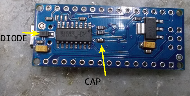
To end my Nano board roundup, this Nano is well made and works, but has the older (slower) boot loader, it works fine but departs from the standard Nano with the addition of a device in the top LH corner, it may be a voltage reference for the Nano. There appears to be no way to isolate USB +5V input from Nano +5V, if you wanted to isolate this along with the USB reset, this is not the board to use. The link to the circuit does not show the extra components, and incorrectly shows a diode linking +5V USB to +5v Nano, this is not the case. This is only my personal opinion and experience, but I would not put a Nano into an Inverter without USB +5v and Reset input disabled. I can safely plug and unplug my Laptop into the USB socket with the Inverter running a load. I have a USB skt from the Nano on the side of my Inverter cabinet. There is now no way a USB connection can interfere with the Nano +5v supply, or cause the Nano to Reset while the inverter is running. The ease of setting up and configuring the Inverter is worth it IMHO. Without the removal of the Reset pathway, you will reset the Inverter when you use the USB port. If you think that you can set the inverter up without the Inverter running, then that's fine, and resetting the Nano should not cause any issues with no or little load, I did that when testing the Inverter with over 40 resets, but that was with a small 200W fan as the load and with a current limited supply, which never tripped. However, I found that in order to fully setup the inverter, and calibrate it accurately, the final adjustments needed to be made with the inverter running and fully warmed up. Knowing that you can use the USB port and not interfere with the Inverter is reassuring. Without the reset mod, if you forget and plug a PC into the USB port while the Inverter is under a good load, and you are happy to have it reset, then you just might void your warranty  Perhaps I'm just being overly cautious  Edit for anyone interested. Version 6.4 Ver 6.4 download . Edited 2024-06-19 16:24 by KeepIS It's all too hard. Mike. |
||||
| KeepIS Guru Joined: 13/10/2014 Location: AustraliaPosts: 1679 |
Just an FYI, a re-occurrence of a previous observation from a few years back, it concerned loosing time on some devices while running from "some" Inverters. We have a large late model Sharp Microwave, it's used for thawing pet food. I don't like microwaves for a number of reasons but that's a different story. This Microwave has a clock that is obviously synced to the mains frequency. Some inverters cause it run slow after a few days. The last EG8010 inverter kept time, some previous inverters also based on the EG8010 did not. The Nano AC frequency can be set to 49.939Hz or 50.002Hz. It was set to the lower, and causes the microwave to loose time. Note, the accuracy of these readings may be influenced by noise. The measured AC mains frequency is slowly varying between 49.993Hz and 50.022Hz. Changing the Nano to 50.002Hz, which measures 50.013Hz AC, should allow the microwave to keep better time. I'm pleased to say that I've had no lost or gained time over the past few days. EDIT: Download link in previous post now v6.50, has an freq option in full menu. . Edited 2024-06-20 15:12 by KeepIS It's all too hard. Mike. |
||||
| -dex- Regular Member Joined: 11/01/2024 Location: PolandPosts: 99 |
Thanks to KeepIS, this can be very useful, although my wife has already got used to changing the clock every day at the oven, which is a few minutes late every day  |
||||
| KeepIS Guru Joined: 13/10/2014 Location: AustraliaPosts: 1679 |
Thanks dex, the digital clock/timer lost over 15 minutes in 3 days, and I'm the one who had to reset it every time  . It's all too hard. Mike. |
||||
| tinyt Guru Joined: 12/11/2017 Location: United StatesPosts: 438 |
Thanks for this info. it seems that the EG8010 60Hz selection is not accurate. My pool timer which uses a 60 Hz synchro motor runs slightly faster when driven by the EG8010 based inverter. Even when I added an LC Pi filter at the synchro motor power line. Edited 2024-06-21 23:10 by tinyt |
||||
| KeepIS Guru Joined: 13/10/2014 Location: AustraliaPosts: 1679 |
Thanks also for that information, another one I hadn't thought of, I put it down to Xtal tolerance/padding. Nice to be able to trim it in the Nano though. . It's all too hard. Mike. |
||||
| KeepIS Guru Joined: 13/10/2014 Location: AustraliaPosts: 1679 |
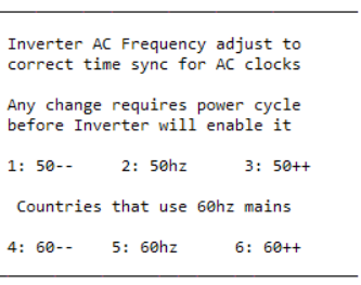
I decided to add a 60Hz (60.08) option for obvious reasons. I've tested this in the Inverter and obviously all is good, however, if someone uses 60Hz in countries with 50hz equipment, what can I say  Some equipment may not be happy. Some equipment may not be happy. I have included a new LCD Nano file in the upload, this auto detects the baud rate change when operating at at 60Hz. These frequencies can vary slightly depending on the Nano xtal, if it's needed I can make just two settings of 50 and 60Hz, each could have a fine +- adjustment. Any change made in the Menu will not be indicated, and the Controller will not change frequency, until the Inverter has been fully power cycled (no +5v), the LCD will only initiate a baud rate change detect at power-up or reset. Same download link as a few posts back for anyone interested in having a play. . Edited 2024-06-22 19:21 by KeepIS It's all too hard. Mike. |
||||
| KeepIS Guru Joined: 13/10/2014 Location: AustraliaPosts: 1679 |
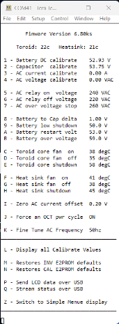
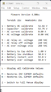
Well that was easy, simple "very slight" trim of the AC frequency for some equipment that uses AC frequency to sync a timer or clock. The first menu below is a poor, reduced in size view of the the Full menu, the setting for AC freq is item K Below that is the menu entry screen when K is selected. And finally the Compact Menu. Last item Z Switches between compact and Full each time it's selected. Full:  K selection  Compact Menu:  ver 6.8 . Edited 2024-06-24 07:48 by KeepIS It's all too hard. Mike. |
||||
| KeepIS Guru Joined: 13/10/2014 Location: AustraliaPosts: 1679 |
Found this old Latronics PV Inverter, Max PV rating of 100v, Rated at 1.25kW AC. The toroid is a lot smaller than the Aerosharp, which will be used in a backup inverter. The toroid connected up to my test bed, it has a separate 19VAC winding and produces 230vac, I just swapped it over with the Aerosharp in the test inverter setup and powered it up. Idles at 22W and it will be ideal for a wiseguy electronic Variac build that I have planned, it's not that heavy and will make a nice compact Variac, AND cost nothing! . It's all too hard. Mike. |
||||
| KeepIS Guru Joined: 13/10/2014 Location: AustraliaPosts: 1679 |
The choke in the foreground in the previous post was from the PvEdge, it came attached to the toroid, it measured around 1.8 mH which is useless and was not used. The choke behind it is 43uH, in one side of the spwm drive, this is also too big. I have a 19uh on the other side and complained here a few times about not having any small toriods to make the correct sized 21uH choke. I stripped the PvEdge choke and it had what had I hoped for, 4 large hole toroid rings, a quick guess of 6 turns resulted in 22uH. The Aerosharp toroid was not happy with a high 43uh combined with a 19uh for a total of 62uh. I have proven in every inverter I have built that a total of around 41uH preforms best with toroid chokes in these inverters. The exception was standard inverter 8010 spwm drive boards, these only need one choke. The wiseguy symmetrical drive versions and the Nano need two, use a similar value as one choke but the inductance is divided across two chokes. What a difference: The idle current dropped from 22W to 14W, the little toroid is now completely silent instead of a slight buzz. So I also scored the choke toroids I needed for the backup inverter. This is consistent with the inverters I've built, BTW testing an ferrite E-core wound to 22uH did not improve the inverter and created other issues under load. Quick 6 turn lash up gave 22uH. The 43uh choke it replaced (it was all I had at the time) Edited 2024-06-25 08:05 by KeepIS It's all too hard. Mike. |
||||
| KeepIS Guru Joined: 13/10/2014 Location: AustraliaPosts: 1679 |
Built the New R7 controller board, happy to see it run first go, and currently running the test inverter. I used the KA7805 gated linear reg, generously supplied by wiseguy. I mounted it in the existing location and added a tiny stick on heatsink, [I will put a clip on it] I don't want it falling off into the controller one day. It runs fine without one, but it runs "finer" with one. I'm going to use that handy breadboard area (bottom front Left on PCB) to fit a 2 pin terminal for my DC over current input. . Edited 2024-06-29 08:32 by KeepIS It's all too hard. Mike. |
||||
| KeepIS Guru Joined: 13/10/2014 Location: AustraliaPosts: 1679 |
The new R7 controller has been running for a few hours in the main inverter powering everything. There is a very small amount of air movement through my inverter cabinet, turns out this was enough to keep the 7805 regulator in the R6 PCB only warm to touch. On the bench, the 3 terminal 7805 5v reg is now quite warm, however these things can take some serious heat and it should be fine, but again, a small heatsink keeps it much cooler. The KA7805 4 pin reg in the new R7 board has a tiny heatsink, and runs slightly warm on the bench. It's all too hard. Mike. |
||||
| KeepIS Guru Joined: 13/10/2014 Location: AustraliaPosts: 1679 |
For anyone interested. A slight user error in settings might cause an AC over-voltage trip to not indicate the error - fixed. Ver 6.9 . It's all too hard. Mike. |
||||
| disco4now Guru Joined: 18/12/2014 Location: AustraliaPosts: 896 |
I can't quite see from the pictures, how did you manage to swap the 5v and GND pins. (They do need swapping around?) Gerry Latest F4 Latest H7 |
||||
| KeepIS Guru Joined: 13/10/2014 Location: AustraliaPosts: 1679 |
There are a few ways, creative bending of the Vo and Gnd pins.  Or bend Vo back at 90° and cut short, a small wire from Vo to Vo pad, similar to what I did for the CTRL pin with the Zener and 1.2k, using spare ground and 12v pcb holes. And obviously the way Mike did it, but I wanted to use the breadboard area for a two Pin plug / socket for DC O-C trip input, instead of using the PCB pin for same. . It's all too hard. Mike. |
||||