
|

|
Forum Index : Windmills : F&P@PE
| Author | Message | ||||
oztules Guru Joined: 26/07/2007 Location: AustraliaPosts: 1686 |
Gordon, It is difficult to drool when there are no pictures... 
...........oztules Village idiot...or... just another hack out of his depth |
||||
| GWatPE Senior Member Joined: 01/09/2006 Location: AustraliaPosts: 2127 |
For the readers who like pictures, here is the stator so far. 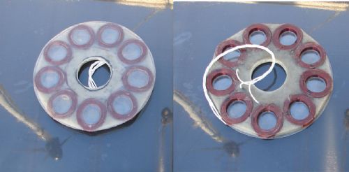
The coil centre holes and the final encapsulant glass layer and mounting holes are still to be done. The 12 magnet centres will be on a 220mm dia circular arangement. Gordon. PS edit: Hi Gizmo, I leave the cutting process up to the guys who do it. The work so far with the 10mm steel plate is an excellent finish [you can just feel the cut edge when you run your finger nail along it]. I requested a similar finish for the Aluminium. I know they have all the gear, and the gas compositions and flow are apparently computer controlled with the laser energy. become more energy aware |
||||
oztules Guru Joined: 26/07/2007 Location: AustraliaPosts: 1686 |
10:35 request for pictures... 10:37 pictures arrive. Now thats service Gordon 
....oztules Village idiot...or... just another hack out of his depth |
||||
| GWatPE Senior Member Joined: 01/09/2006 Location: AustraliaPosts: 2127 |
Sorry Oztules, this was coincidence only. become more energy aware |
||||
| Gizmo Admin Group Joined: 05/06/2004 Location: AustraliaPosts: 5078 |
All laser cutters these days use computer controlled laser power, feed rates, gas pressure, etc. What I should have said was cutting aluminium on a laser is more expensive that cutting steel. However, cutting aluminium on a waterjet is cheaper than cutting steel. So if you have a choice between laser or waterjet, then go waterjet for aluminium, laser for steel. Either way, get a quote. In this case, $20 is pretty good. Glenn The best time to plant a tree was twenty years ago, the second best time is right now. JAQ |
||||
| GWatPE Senior Member Joined: 01/09/2006 Location: AustraliaPosts: 2127 |
For those who are puzzled by what the magnet positioning template will look like. 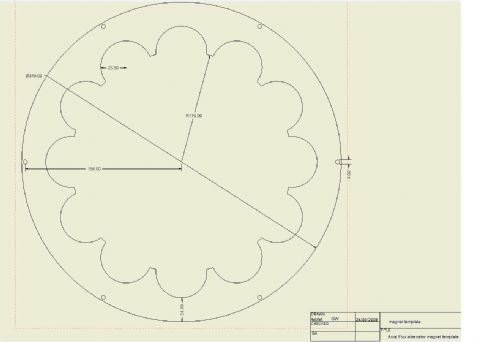
Too hard to make by hand! Gordon. become more energy aware |
||||
| Tinker Guru Joined: 07/11/2007 Location: AustraliaPosts: 1904 |
Glenn, a laser cutting question for you if I may ask. Do they need the cutting data in computer code or would a scale drawing on graph paper suffice for laser cutting a small quantity (12 pieces)? Scale drawings are doable here but I'm too old to learn programming now.... Thanks Klaus |
||||
| vasi Guru Joined: 23/03/2007 Location: RomaniaPosts: 1697 |
-- here was the image -- Too hard to make by hand! Gordon. Hi Gordon, You are considering to keep that template for final product (fixed with screws)? I think it will be an insurance against centrifugal force ... If the material is plastic, then can be made with a fretsaw? Hobbit name: Togo Toadfoot of Frogmorton Elvish name: Mablung Miriel Beyound Arduino Lang |
||||
| GWatPE Senior Member Joined: 01/09/2006 Location: AustraliaPosts: 2127 |
Hi vasi, the template will be used only to accurately position the magnets on both disks. The flux and some epoxy glue and maybe some carbon fibre will fix the magnets to the plates. The closed arrangement of the design will help with plate rigidity, so the magnets will stay put. I am prepared to make parts by hand where necessary, but the acccuracy of the placement determines output wave shape quality and balancing of the rotor. It would also cost more! Gordon. become more energy aware |
||||
| GWatPE Senior Member Joined: 01/09/2006 Location: AustraliaPosts: 2127 |
The final specs for the new AxFx alternator have needed some revision. After some rechecking and testing of full sized coils, the output emf is higher than expected. I have to remove some turns, as I do not intend to up the wire size. This leaves a lot of space between the coils. The solution was to redo the magnet gap and adjust the turns etc. The final best fit has resulted in a reduction of the magnet gap from 18mm down to 12mm, and the number of turns from 100 down to 64 per coil. The magnets have moved out a bit as well. The coils have dropped from 0.25ohms to 0.15ohms each. This has reduced the between phase resistance to 0.9ohms. This is more like what I had originally estimated for a 48V machine. A spinoff will be a lighter machine with a lighter, lower resistance stator and less metal in the spacer ring. All good really. There will be an increase in the pull between the magnet rings as well, so a little more effort will be required on the jacking bolts. The capacitor voltage doubler will still allow cutin at 100rpm. I will be experimenting with electronic disconnection of the doubler as the first overvoltage protection measure, before the final mill shutdown sequence is engaged. I am considering all options that reduce the need for power dissipating elements. Still some more experimenting needed. Gordon. become more energy aware |
||||
| GWatPE Senior Member Joined: 01/09/2006 Location: AustraliaPosts: 2127 |
I have procured the necessary caps, rectifiers and mosfets for the voltage multiplier/main rectifier/regulator units at a good price. All components under $1 each. Still working on coil winding, and have decided to have the components for the stator mould laser cut as well. I have looked at a simple mosfet, winding shorting brake that will work on the AC side, in conjunction with the rectifiers. This will activate from generated emf, so will give unloaded windmill rpm protection as well. I have used a similar arrangement on my original AxFx windmill, to protect the Shottkey diode bridges. The finished alternator/controls are is still a bit of a way off yet. Gordon. become more energy aware |
||||
| GWatPE Senior Member Joined: 01/09/2006 Location: AustraliaPosts: 2127 |
Just an update on my new AxFx alternator. The machining of the dual rotors and the bearing housing and stub axle and the ring has been finished. Zest engineering came up trumps again. Thanks windman. I have now trimmed and fitted the stator and am finishing the tedious process of magnet placement and encapsulation and environmental sealing of all the metal. The initial testing shows a very electrically stiff alternator. I will be checking the output voltage vs rpm in the next phase. The shorted winding test was like trying to stir peanut paste straight from the fridge. I will be posting some more photos. The encapsulation process has ended up with fridge white as the colour, with a zinc undercoat. The waterproofing will be 2 layers of a 2pak epoxy finish on all interior surfaces. The jacking system allows relatively easy separation of the dual rotors with safety. Photos should help show things. This machine has been wound for connection to a 24V and 48V loading, so I still have to work out the capacitor arrangements for optimum loadings. I want the low end power to charge my 24V battery, and the high end power will be diverted directly to the 48V battery and grid inverter. Most of the average power is in the 24V area, but the high end power I still want to harvest. I do not want relays and switching systems on the windings. The present stator has no options in this way, as it is internally wired in star with 3 series coils per phase, with 3phases. I do intend to log this mill, with possibly a suite of sensors and a radio transmission link from the mill head of stator temperature. Some benefit has to come of the work to date from the super piclog and battery logging systems I have made. Gordon. become more energy aware |
||||
| GWatPE Senior Member Joined: 01/09/2006 Location: AustraliaPosts: 2127 |
Some photos of the different sections. These are progress shots prior to final environmental sealing. The finished items are not much different to the CAD piocs presented prior. The ring is a 12"nom pipe. The unit is 2 1/2" thick. 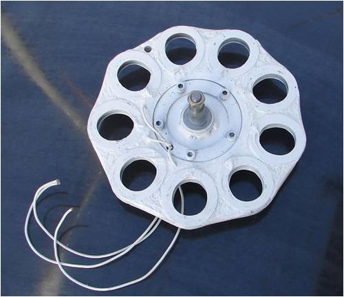
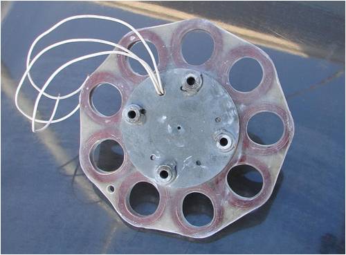
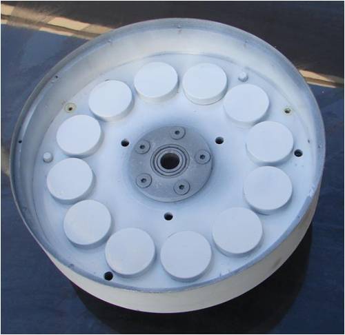
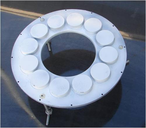
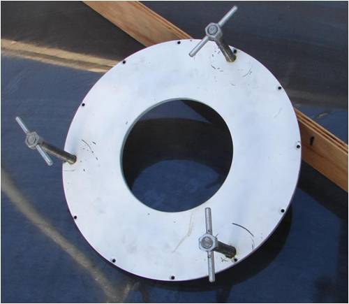
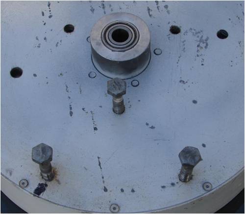
The pics are pretty self explanatory. Gordon. become more energy aware |
||||
fillm Guru Joined: 10/02/2007 Location: AustraliaPosts: 730 |
Hi Gordon , All looks good ,by the looks hopefully it will be up and flying soon and some output data will be posted to see the differences between 100 turns to 64 turns in the coils . How far do your jacking bolts raise the rear rotor before the magnetic field is clear ? PhillM ...Oz Wind Engineering..Wind Turbine Kits 500W - 5000W ~ F&P Dual Kits ~ GOE222Blades- Voltage Control Parts ------- Tower kits |
||||
| GWatPE Senior Member Joined: 01/09/2006 Location: AustraliaPosts: 2127 |
Hi fillm, The jacking bolts are 100mm long. Gordon. become more energy aware |
||||
| GWatPE Senior Member Joined: 01/09/2006 Location: AustraliaPosts: 2127 |
Output figs just to hand are 60rpm gives 18VAC between phases, so this will give 24V battery charging at under 100rpm. Looks like a series cap config to the 24V bank will suffice. Power limited to approx 150W with the cap sizing. A cap voltage doubler for the 48V battery will then add to the loading, followed by direct coupling to 48V at around 200rpm. This will provide a steady charging of my 24V house inverter UPS battery, and surplus power will be directed to the appliances connected on the grid side at the upper power levels only. A fair bit of the wind energy from my F&P mill is missed in the low wind energy region,[a decogged F&P still sits idle a lot of the time], so the AxFx will cover this well. My prime objective is to top up the battery first. I will now have 2 AxFx mills covering this aspect. I still have the rear plate fastening screws to drill and tap and then the unit can be wind tested. The overvoltage protection has worked well on the F&P, so it should not be too much more before real testing can begin. Gordon. become more energy aware |
||||
| Gizmo Admin Group Joined: 05/06/2004 Location: AustraliaPosts: 5078 |
I have to say that is a sexy looking stator. I'm pretty keen to build one of these, but it will have to wait until I have moved into my new place. Glenn The best time to plant a tree was twenty years ago, the second best time is right now. JAQ |
||||
| brucedownunder2 Guru Joined: 14/09/2005 Location: AustraliaPosts: 1548 |
Nice work , Gordon. You and Phill have done some nice working machines during the last year or so ,good for you both and all of us here at "Homegrown Power" send our thanks. I'm concreting a slab for my firewood shed at present ,plus power and lights under the house , so not much in the old wind gennie Dept. lately. Will keep in touch and follow your and Phill's results. Thanks Bruce Bushboy |
||||
oztules Guru Joined: 26/07/2007 Location: AustraliaPosts: 1686 |
Very good figures there Gordon. You have done the homework well from the looks of it. Interesting to see if it needs some R in the line or not. 60 rpm is darn slow for cutin. 18vac ... 25vdc?. (you mentioned previously you were aiming for 100rpm... near charge the 48v unit then.) It seems you have got Glen pondering an axial.... is that sacrilege of some kind? ............oztules Village idiot...or... just another hack out of his depth |
||||
| Gizmo Admin Group Joined: 05/06/2004 Location: AustraliaPosts: 5078 |
You know, I did build one once. It did work OK. I wont say anymore for fear I might incriminate myself. 
Glenn The best time to plant a tree was twenty years ago, the second best time is right now. JAQ |
||||