
|

|
Forum Index : Electronics : OzInverter OzCntrl PCB rev12 Sept2017
| Author | Message | ||||
| Warpspeed Guru Joined: 09/08/2007 Location: AustraliaPosts: 4406 |
Way back on page three of this thread I posted a link to a handy on line flux calculator. https://www.electricaltechnology.org/2014/02/maximum-flux-density-bmax-calculator.html For an unknown toroid that already has a 230v winding, its first necessary to work out the volts per turn by measuring the voltage across a few experimental turns and energising the 230v winding from the grid. From that you will know the volts per turn, and by physical measurement the magnetic cross sectional area of the toroid. The mathematics are straightforward, but that on line calculator eliminates any possibility of confusion. Most commercial toroidal transformers use a flux density of around 1.5 Teslas, and you definitely would not want to go much higher than that for an inverter. Any reduction below 1.5 Teslas will repay you with a disproportionally much greater reduction in no load inverter idling power. If you plug the above figures into that calculator: RMS voltage 3.25 volts (for one turn) Frequency 0.00005 Mhz (50 Hz) Turns 1 Cross sectional area 91 square cm. It spits out 1.6088 Teslas. That is high, not dangerously high, but just about at the safe limit. That 3.25 volts per turn suggests the 230v winding may have about 71 turns. I think I would add another ten turns to that secondary bringing it up to 81 turns. That would lower the flux density to around 1.4 Teslas. It would certainly work at 1.6 Teslas, but you will pay for it in sucking a lot of useless extra idling power from your battery at night. Cheers, Tony. |
||||
| brac321 Regular Member Joined: 30/11/2016 Location: SloveniaPosts: 54 |
Thanks Warpspeed and Clockman. So, flux calculator gave me 1.255 Teslas for my trany without adding any winding on 230v. I will try it tomorrow live (idle current) with the boards, using a temporary low voltage winding. EDIT: didn't wait for morning...  Idle power with this large trany (only 4 FETs on power board) goes from 21.30 W @ 48v and slowly rising up to 22.04 W @ 58v DC. But, I have not played with inductivity of choke yet. On the modified PJ with all mods I got up to 4 w less, but transformers there are much smaller and it take me days of experimenting with various chokes... I'm happy for now. OffGrid 24/7: 250w black mono solar panels 6.4kWp, 1x Midnite Classic 150, 1x MorningStar MPPT 60, battery bank 840 Ah @ 48v, modified LF-8K inverter, DC/DC, hot water harvesting, etc. |
||||
| Warpspeed Guru Joined: 09/08/2007 Location: AustraliaPosts: 4406 |
Great stuff there Brac. 1.255 Teslas is excellent, you won't be disappointed. Magnetising current is measured in watts per Kg of core mass at a specific flux density, so its more difficult to keep the no load losses very low with a very large core. But the trick to it is to lower the flux density, even a small amount, if that is practical. The only down side is that a higher turns count uses up more of the centre hole. That means thinner wire, and more heat and higher losses at full flat out power. But for a domestic off grid inverter its a good tradeoff to have less idling current and higher efficiency at low power, where the inverter spends most of its life. Cheers, Tony. |
||||
| brac321 Regular Member Joined: 30/11/2016 Location: SloveniaPosts: 54 |
Idle power of Siemens 7k9 trany 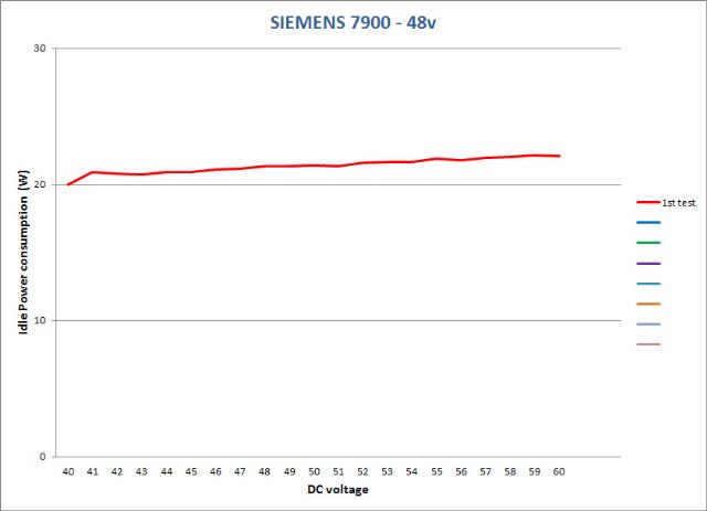 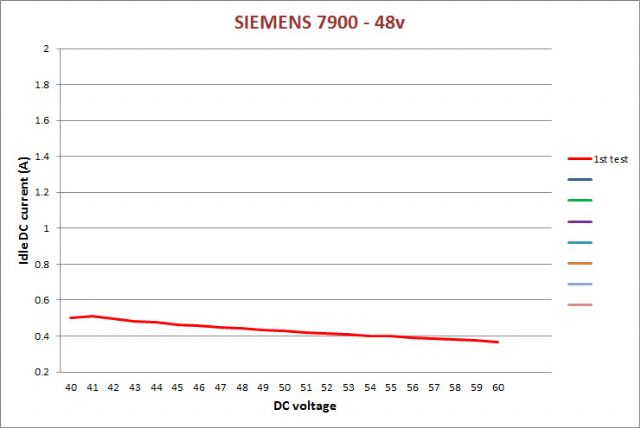 OffGrid 24/7: 250w black mono solar panels 6.4kWp, 1x Midnite Classic 150, 1x MorningStar MPPT 60, battery bank 840 Ah @ 48v, modified LF-8K inverter, DC/DC, hot water harvesting, etc. |
||||
| Warpspeed Guru Joined: 09/08/2007 Location: AustraliaPosts: 4406 |
That is outstanding considering the potential power output capability. Cheers, Tony. |
||||
| Clockmanfr Guru Joined: 23/10/2015 Location: FrancePosts: 429 |
Thanks Warpspeed for your excellent and clear clarifications. Especially your observations on the Telsa in regards wattage draw when the inverter is on standby/idle. I suspect that you find the OzInverter project interesting? Everything is possible, just give me time. 3 HughP's 3.7m Wind T's (14 years). 5kW PV on 3 Trackers, (10 yrs). 21kW PV AC coupled SH GTI's. OzInverter created Grid. 1300ah 48v. |
||||
| Clockmanfr Guru Joined: 23/10/2015 Location: FrancePosts: 429 |
Well done brac321, your getting there. Its always difficult for me when folk say, "I have this ready wound toroid of 7.6kva rating". After seeing what the PJ claim there toroid's will do against there real claims, and what some manufacturers rating claims, and what 'Warpspeed' mentioned about manufacturers of toroid's cutting everything to the bone/minimal, I am therefore very sceptical of any so called prewound toroid ratings. 'oztules' took the time to coat each secondary winding with epoxy before putting the next mylar/insulation wrapping on. Like 'oztules' I also want a long life Inverter, and seeing and hearing about old toroid's that have shorted out on there windings, makes me realise that the thin epoxy coating locks those secondary windings, and stops that buzzing/vibrations and ultimately stops that interior toroid fail. Everything is possible, just give me time. 3 HughP's 3.7m Wind T's (14 years). 5kW PV on 3 Trackers, (10 yrs). 21kW PV AC coupled SH GTI's. OzInverter created Grid. 1300ah 48v. |
||||
| Warpspeed Guru Joined: 09/08/2007 Location: AustraliaPosts: 4406 |
Oh the Ozinverter is certainly interesting, in fact way beyond interesting. I have several other projects going right now in various stages of completion, but plan to build an Ozinverter myself quite soon. Have all the parts here ready, I just need to pull my finger out. Current priority project is a rather nice home brew battery management system that has a direct VGA video output to drive a flat screen monitor. I have been working on this for months. Its all going except it needs a bit more hardware development work on the cell balancing system to get it working exactly how I want it to work. These Lithium batteries are mighty impressive things, and deserve a bit of tender loving care. Once that is done, the charger comes next (almost complete), then the inverter. Hope to have the potential to have off grid night time power by Christmas. Already totally off grid during the day, but that is only half a solution. Cheers, Tony. |
||||
| Clockmanfr Guru Joined: 23/10/2015 Location: FrancePosts: 429 |
Whoops! sorry 'warpspeed', I have a spelling mistake, it should be Teslas Everything is possible, just give me time. 3 HughP's 3.7m Wind T's (14 years). 5kW PV on 3 Trackers, (10 yrs). 21kW PV AC coupled SH GTI's. OzInverter created Grid. 1300ah 48v. |
||||
| Warpspeed Guru Joined: 09/08/2007 Location: AustraliaPosts: 4406 |
Transformer manufacturers are not charitable institutions, they are in it for profit. And good for them ! But we are doing this for ourselves, and we can make something just a little bit nicer and a lot more efficient by being a bit more generous with copper and steel, and optimising the design to suit our own rather special needs. There is a lot to be gained by thinking the whole thing right through, and then putting in some hard work and testing. Cheers, Tony. |
||||
| brac321 Regular Member Joined: 30/11/2016 Location: SloveniaPosts: 54 |
Power board / Ferrite Beads on low side of FET bridge, shall we install them? Some Chinese boards use them on FET's Drain. I guess they are useless there (inside short death loop). Heat sink and back side of FET's are already on same potential as each tiny Drain pin that after going through the Bead ends on same plane. It could of some importance on microwave frequencies, but here on extremely low frq. ... don't know. Any idea? Clockman, have you removed (scratched down) Stop-mask under both low side heat sinks? Because of high currents and connection to the Source of FET's at High side, the complete current will flow only trough tiny legs at Low side FET's. In my view it is not the best idea to have isolation there. Both small heat sinks shall be mounted with the best contact to PCB copper under. What do you think? OffGrid 24/7: 250w black mono solar panels 6.4kWp, 1x Midnite Classic 150, 1x MorningStar MPPT 60, battery bank 840 Ah @ 48v, modified LF-8K inverter, DC/DC, hot water harvesting, etc. |
||||
| Warpspeed Guru Joined: 09/08/2007 Location: AustraliaPosts: 4406 |
I have never used ferrite beads with mosfets in power circuits, only suitable place seems to be in the gate lead. But there should be a low value series gate resistor in there somewhere, which should be all that is required to damp out any ringing. What will function fine, and what might be needed to pass a formal EMC emissions test are two very different things. Fitting ferrite beads can be a quick low cost solution if something almost passes, and a particular component is generating a ringing waveform that radiates RF. Slip on a bead, and the problem goes away. Some nasty spur on a spectrum analyzer shrinks below the fail line. So you sometimes see small ferrite beads fitted in some mighty strange places. Ferrite chokes in series with the transformer primary were in fashion here a while back, and definitely reduced idling power. I suspect it reduced mosfet turn on switching loss by slowing down the rate of initial current rise when switching into a highly capacitive load caused mostly by the transformer self capacitance. These ferrite chokes would quickly saturate above idling power, but proved to be very effective at lowering idling power level. A much better approach to all this would be a serious steel cored non saturating choke with large air gap, in series with the transformer primary. That turns the PWM side of the bridge into something that looks like a buck regulator, and in combination with the transformer self capacitance turns our PWM into a nice sine wave. Transformer self resonance is typically at only a few Khz, well below our PWM switching frequency. At 20Khz (well above resonance) the transformer looks very strongly capacitive. In fact on some of the waveforms pictured in various threads here, you can actually see a faint low amplitude ripple superimposed on top of the 50Hz of perhaps one or two percent amplitude that appears to be in the low Khz range. Its nothing to worry about, but its an interesting phenomena. A second advantage of having a big steel non saturating choke, is that it slows down the rate of rise of any fault current, at least until the choke saturates. That slow down and delay in rate of current rise gives any overload shut down system at least a fighting chance. Some of the commercial grid tie inverters use a choke large enough not to saturate at about roughly twice the peak full load running current. That is probably a fairly safe and reasonable objective. With a multi Kw inverter, that choke is going to be pretty huge, but still I think well worth having. Cheers, Tony. |
||||
| brac321 Regular Member Joined: 30/11/2016 Location: SloveniaPosts: 54 |
Yes Tony, I was thinking too about choke saturation and how to enlarge ferrite ring cross section (one I use) not to saturate too early. But after measuring and calculating inverter efficiency at various loads, was quite surprised how well it perform even at higher loads. So I left PJ LF as it is after all modifications. It powers my complete home, both buildings 24/7 - it was my most powerfull inverter. But now I have few pwr boards for Ozinverter, so plenty of room to play with  Two friends of mine, one in Slovenia, another in neighboring Austria have got huge factory made 35kW 3f inverters, 2nd hand. But both suffers of (too) high idle current. So they are looking now for 10-15kW ones. Here is one in Austria - rack in upper left corner 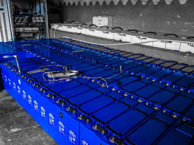 OffGrid 24/7: 250w black mono solar panels 6.4kWp, 1x Midnite Classic 150, 1x MorningStar MPPT 60, battery bank 840 Ah @ 48v, modified LF-8K inverter, DC/DC, hot water harvesting, etc. |
||||
| Warpspeed Guru Joined: 09/08/2007 Location: AustraliaPosts: 4406 |
Ferrite saturates at only about 0.35 to 0.4 Teslas. Grain oriented silicon steel, probably more like 1.8 Teslas. Crappy low grade E and I transformer laminations probably about 1.5 Teslas. Your ferrite needs to have about five times the cross sectional area, and ferrite is very expensive in the larger sizes. A second issue is high frequency core loss. Chokes that run with very low ripple current have a very low ac (magnetic) component, its mostly just the dc. So we can get away with using a laminated steel core in our choke, and very thick solid wire as skin effect is not an issue here either. Although the choke is being fed with PWM at 20Khz, we can build our choke as a low mains frequency choke, provided it has sufficient inductance to reduce any ripple current down to a small fraction of the bulk dc current. I plan to use a low frequency E and I stamped laminations choke that I designed years ago as a filter choke for a 50Hz rectifier used in a battery charger. It has just about ideal inductance and current rating for use as a PWM inverter choke. Its very large, but as I already have it, it will be used as is. Cheers, Tony. |
||||
| brac321 Regular Member Joined: 30/11/2016 Location: SloveniaPosts: 54 |
Have you made any useful filters on DC input side of inverter? There is plenty of HF disturbance that spreads around from inverter trough DC installation ... OffGrid 24/7: 250w black mono solar panels 6.4kWp, 1x Midnite Classic 150, 1x MorningStar MPPT 60, battery bank 840 Ah @ 48v, modified LF-8K inverter, DC/DC, hot water harvesting, etc. |
||||
| Warpspeed Guru Joined: 09/08/2007 Location: AustraliaPosts: 4406 |
I have not yet reached the stage of seriously testing my PWM inverter. I had a rough prototype running at low power, then ordered a proper circuit board for it, which is now assembled. But I have not yet attempted to go through the slow process of slowly bringing it to life. My system is a bit unusual in that its only low power 2.4Kw max, and runs at 100v to 140v dc straight from the solar panels. There will be a large bank of electrolytics probably about 20,000uF to absorb the 100 Hz pulsing current demand from the inverter during the day. At night the inverter will run from a 100v 50Ah (5Kwh) Lithium battery. There may be EMI problems, I really do not know. But they should be far less and easier to solve than with a much more powerful lower dc voltage system. Cheers, Tony. |
||||
| yahoo2 Guru Joined: 05/04/2011 Location: AustraliaPosts: 1166 |
Hi Tony, I was kinda disappointed you didn't go with one of the standards. 39 LFP cells slots into the 120 volt nominal window very nicely (3 packs of 13 cells). It would have helped me a lot to peer over your shoulder and see what inverter components you have chosen  . Purely for my own self interest. . Purely for my own self interest.The higher voltage systems are the most trouble free I have worked on apart from two things. Doing the cell connections is up there with transformer winding as a PITA, usually takes me a full day (lots of cleaning prepping and checking) and it needs to be critter proof, you dont want mice nesting on top of warm cells pissing on BMS connectors and chewing wires  I have tried to explain to people what a good small inverter matched with LFP cells is like. The best analogy I have come up with is what sized generator would you need to match it? A 3.5 kw system will smoke most 9-10 kva generators. I get a little frustrated when people keep buying massive low voltage inverters and sh*tty batteries. I'm confused, no wait... maybe I'm not... |
||||
| Warpspeed Guru Joined: 09/08/2007 Location: AustraliaPosts: 4406 |
Ah, I have had this long term evil plan of fitting thirty 50Ah Winstons into a standard filing cabinet drawer. They fit wonderfully well packed 6 x 5 with just enough space available to clamp between two 6mm steel plates. It may all sound a bit odd, but I am pretty happy with how its all turning out. That gives me 100 volts nominal when each cell is 3.333 volts, right in the middle of the operating range. Its built into a sort of "battery trolley" that wheels out for maintenance and full access, and normally sits parked inside some recycled metal parts recovered from a reincarnated filing cabinet. It actually looks a lot better than it probably sounds. Yes indeed, so many cells require so many small parts for connecting up, and monitoring. A real PITA. Sixty of some things, and thirty each of many other things. The heart of it though is the thirty cell BMS, with an on screen colour graphical display of thirty cell voltages, with max and min peak hold of the extremes each cell finally reaches. That part is all working, and it looks rather nice. No pictures unfortunately until I replace my dead camera. The whole (rather small) off grid system will be enclosed in something no larger than a single drawer filing cabinet, with no exposed parts or wiring. Cheers, Tony. |
||||
| Clockmanfr Guru Joined: 23/10/2015 Location: FrancePosts: 429 |
Brac321, Oztules and I discussed the Power board connections back in 2015. In conclusion it would help, but the present board design is very capable. I still ask that you insulate the heatsinks from the top tracks as just a slither of copper being pushed through the varnish coating and shorting out on the top tracks could mean disaster!. I think you have 2 of my early Power boards, the ones that Oztules tested to the ultimate, and a more recent design. Both designs of the Power board are fundamentally the same except for re-positioning of text/silk screen and the modification to the Battery + 48vdc long heatsink mounting connection. This +48vdc heatsink, the long one, now has its holding bolts/screws directly connecting with the PCB bottom copper track. see photo of a early Power Board modified. 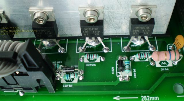 Everything is possible, just give me time. 3 HughP's 3.7m Wind T's (14 years). 5kW PV on 3 Trackers, (10 yrs). 21kW PV AC coupled SH GTI's. OzInverter created Grid. 1300ah 48v. |
||||
| brac321 Regular Member Joined: 30/11/2016 Location: SloveniaPosts: 54 |
Yes, I saw the differences below all 3 power PCBs, and it is (in my view) all right to have good - best possible contact from large heat sink and the bottom layer of PCB - because of currents at high loads. I would even put there more screws, or at least M4 instead of tiny M3, counting on currents that will flow trough them! Equal situation is on smaller heat sinks, there are same high currents. If we isolate them from upper layers of PCB all the current will flow only trough tiny pins of each FET. I do not like that at all, so will try to remove all the silk paint (stop mask) from the top layer of PCB below them. Don't know yet how quality paint these chinese boards have ... ?  For the isolation below the largest heat sink I use professional stuff - single layer of thin Teflon laminated tape. Non conductive, high voltage, preasure and temperature resistant, made just for such applications. 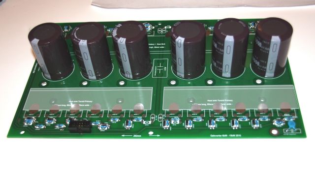 OffGrid 24/7: 250w black mono solar panels 6.4kWp, 1x Midnite Classic 150, 1x MorningStar MPPT 60, battery bank 840 Ah @ 48v, modified LF-8K inverter, DC/DC, hot water harvesting, etc. |
||||