
|

|
Forum Index : Microcontroller and PC projects : Maximite - DuinoMite Prog. Differences.
| Author | Message | ||||
Bryan1 Guru Joined: 22/02/2006 Location: AustraliaPosts: 1344 |
G'day Don, Eh mate with the headers on the duinomite board would you have the dimensions for them. I did see mine was posted out today so hopefully it will be here tomorrow and I do want to a headstart on designing my own shields. Regards Bryan |
||||
donmck Guru Joined: 09/06/2011 Location: AustraliaPosts: 1313 |
http://www.themaximitecomputer.com/donduino-bus-convertor-ta ble/ but take note: Note that the distance between digital pins 7 and 8 is 160 mil (0.16"), not an even multiple of the 100 mil spacing of the other pins. Cheers Don... https://www.dontronics.com |
||||
donmck Guru Joined: 09/06/2011 Location: AustraliaPosts: 1313 |
Mick just reminded me, we have to get a look up table from the 26 pin IDC header of the DuinoMite board to the Arduino shields to know which pin (x) goes to which shield pin, then we can sort out why the LCDs don't work correctly. It may not be sharing at all. Next thing is for me to make a suitable look up table. Did you get anything on the LCD Sparkey? Cheers Don... https://www.dontronics.com |
||||
| sparkey Senior Member Joined: 15/06/2011 Location: AustraliaPosts: 819 |
he don is ken`s "editor " in the mega firm i cold not seem to get it to fire up but it could have been my syntax ...sparkey...///.../// technicians do it with least resistance |
||||
donmck Guru Joined: 09/06/2011 Location: AustraliaPosts: 1313 |
Sorry, don't know the answer to that one Sparkey. Cheers Don... https://www.dontronics.com |
||||
| sparkey Senior Member Joined: 15/06/2011 Location: AustraliaPosts: 819 |
at a further look i dont think that it has been added as the standard 2.7 "edit "line" still works and as i am led to belive when the new editor is used the old one has been scrapped ///well just have to wait for ken `s work on that one.... well getting a little board think i will go and anoy the "rtc" its just sitting there stareing at me ...hmmmm..//..// technicians do it with least resistance |
||||
donmck Guru Joined: 09/06/2011 Location: AustraliaPosts: 1313 |
Eh mate with the headers on the duinomite board would you have the dimensions for them. I did see mine was posted out today so hopefully it will be here tomorrow and I do want to a headstart on designing my own shields. Regards Bryan http://www.themaximitecomputer.com/donduino-bus-convertor-ta ble/ but take note: Note that the distance between digital pins 7 and 8 is 160 mil (0.16"), not an even multiple of the 100 mil spacing of the other pins. Cheers Don... OH, because of the silly spacing of the shields, Olimex in their wisdom have placed an additional bus along side the existing on all DuinoMite boards Bryan. Check out the overlays. So if it is for DuinoMite only, you can use that. If it is for a generic shield, you will need to use the correct spacing. No, I don't have the figures on the "other" footprint at my fingertips. I think you can work it out looking at the boards. But something to think about. Cheers Don... https://www.dontronics.com |
||||
Bryan1 Guru Joined: 22/02/2006 Location: AustraliaPosts: 1344 |
Thanks for that Don, it may pay for me to wait until the board arrives then I can get the exact spacings sorted. I use Sprint Layout for all my pcb design work so when I do get a shield designed I will be happy to post it on here so other members can use them as they wish. Regards Bryan |
||||
VK6MRG Guru Joined: 08/06/2011 Location: AustraliaPosts: 347 |
Mac, what's that? 
Cheers Don... Something from Mc Donalds isn't it?.....  Its easier to ask forgiveness than to seek permission! ............VK6MRG.............VK3MGR............ |
||||
| sparkey Senior Member Joined: 15/06/2011 Location: AustraliaPosts: 819 |
ok i have the time clock connected but i am getting an error on the read the write is fine it may be the program i am using as i have many ...but it is seeing it on pins 5 and 6 of the U=ext on the rear hedder...///...///but i am having trouble with the read program "matt what was error on line 446 ..invalid date " what was the fix for that i cant rember and i will have to go digging i think i need a different read code....here`s a pic.../// 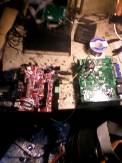
technicians do it with least resistance |
||||
| sparkey Senior Member Joined: 15/06/2011 Location: AustraliaPosts: 819 |
i am oly running the two wires no 5v rail at all and it is seeing it.... there is one thing about having a power good led and a system power led is that if you lose your system function led then therefor it seems to me that there is a deffinite chip malfunction or other system malfunction but if you lose your power good led will u lose system function led as well of corse it makes sense that this would be the case but u never know with electronics it might just mean that the led has a fault .... \ i`m nearly there just have some more code to crack i guess 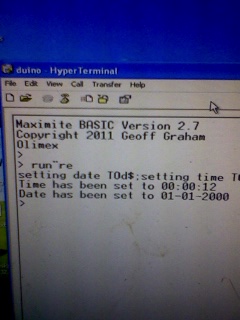
technicians do it with least resistance |
||||
pcaffalldavis Senior Member Joined: 17/10/2011 Location: United StatesPosts: 187 |
When I was getting this error it was because the jumper was NOT set to BAT, so each time you rebooted the RTC went back to not knowing the date/time string. As soon as I changed the jumper to BAT, booted, set the Date$ & Time$ and then ran the clock set program, from then on it worked just fine. Pete in Hyder We're all here 'cause we're not all there. |
||||
| sparkey Senior Member Joined: 15/06/2011 Location: AustraliaPosts: 819 |
thanks for that info but i am if you look at the hardware pic two boaeds one you prolly have not seen and the other is a blown up SM1 board but i have isolated the "rtc" part of the cct and i am running the two rtc signal wires to my dynamite mega have a close look at the picture ...///.../// 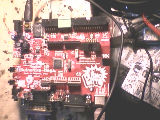
technicians do it with least resistance |
||||
| sparkey Senior Member Joined: 15/06/2011 Location: AustraliaPosts: 819 |
i am still to master the "rtc" but i think it might be down too component level ..now i will have to get the meter on it it seems that i may have an open diode or maybe a short some where...back to the drawing board although it does return a value of "zero" meaning only one thing ..the wires to "U-ext " must be correct...... technicians do it with least resistance |
||||
| sparkey Senior Member Joined: 15/06/2011 Location: AustraliaPosts: 819 |
check this out trend setters.and gurus.....given the fact that the day is in correct but look at "the time and date" theres the ..."RTC working on dynamite" and the rtc is on a SM1 board...jumperd via "U-EXT "at the rear 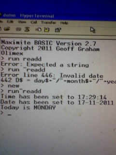
technicians do it with least resistance |
||||
donmck Guru Joined: 09/06/2011 Location: AustraliaPosts: 1313 |
Thanks Sparkey, it may just mean two jumpers on the LCD shield, (Ken's advise) but we are looking at it, and will test the hardware, and change the basic program to match. Cheers Don... Someone told me it was your birthday tomorrow Sparkey, so I pulled my finger out, and sorted out the DuinoMite to Arduino Shield LCD modifications to make it work. So here is your birthday present: http://www.themaximitecomputer.com/duinomite-to-lcd-and-butt ons-arduino-shield-modifications/ As suspected, two track cuts, two jumpers, but it could be simpler in future. Cheers Don... https://www.dontronics.com |
||||
| sparkey Senior Member Joined: 15/06/2011 Location: AustraliaPosts: 819 |
thanks don cheers check this out ....got the "RTC" happening i mean its just a add on its just getting it correct ...any way heres a pic for ya funny what this board sometimes throws out at start up.....have a close look ..... 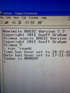
technicians do it with least resistance |
||||
donmck Guru Joined: 09/06/2011 Location: AustraliaPosts: 1313 |
Yes, it only happens on the terminal, not VGA, but Ken is aware, and is fixing it in the next update. Now you have to get the day correct. 
Cheers Don... https://www.dontronics.com |
||||
Bryan1 Guru Joined: 22/02/2006 Location: AustraliaPosts: 1344 |
G'day Don, This might be a silly Q but does the duinomites come programmed with the latest version or just with the bootloader then the user is required to flash the latest version in. Regards Bryan |
||||
| sparkey Senior Member Joined: 15/06/2011 Location: AustraliaPosts: 819 |
don still no go on the l.c.d. the program works but there is no response on the lcd....and the olimex comes with 2 point 7 i gather that the two links are on the1 lcd thats the way that the mod reads.... also the press buttons do actully work its jusat that there is no display on the lcd where normally the vga presents a voltage of 3 volts being that it is reading pin one at a floating point when u press the keys the voltage differs some keys its 1.000 volts approx and other keys its a reading of zero volts if you want exact deatails as i thought this would suffice...///.../// technicians do it with least resistance |
||||