
|

|
Forum Index : Windmills : Requesting selecting wire size for stator
| Author | Message | ||||
| govertical Guru Joined: 11/12/2008 Location: United StatesPosts: 383 |
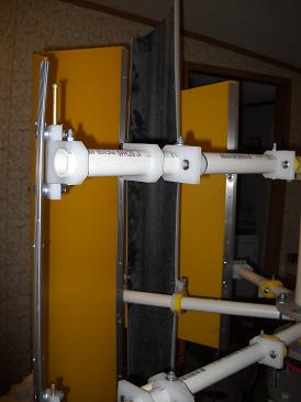
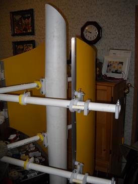
Hi, basically it is the same size, just a different style. I will compare the test result with earlier tests of different blade configurations to see if there is a improvement. From other videos it looks like there may be a improvement. I will know more after the road test. 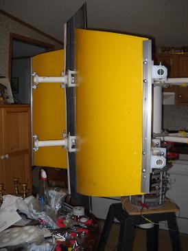
just because your a GURU or forum administer does not mean your always correct :) |
||||
| Greenbelt Guru Joined: 11/01/2009 Location: United StatesPosts: 566 |
Go Vertical HI, I reviewed some of the posts on your project and find that your assembly requires too much force to show a little juice. Some of your road tests at 40 mph. have indicated as much as, or as little as, 84 Watts ?? with all the Mags and Coils and 3 Stators you should be seeing a kilowatt at this speed. Your wiring diagram on the first post, page 1, shows several coils of different phases connected together without a diode indicated. This will not work! I have made a drawing to show the way, If you want Stators connected in parallel do it after the Diodes. I'm Not 100% sure that I have all of this Correct so anyone who sees an error with this post feel free to nail me on it. I do want this information to be reliable. G,V, Nice work Guy! --------------Cheers, Roe Time has proven that I am blind to the Obvious, some of the above may be True? |
||||
| govertical Guru Joined: 11/12/2008 Location: United StatesPosts: 383 |
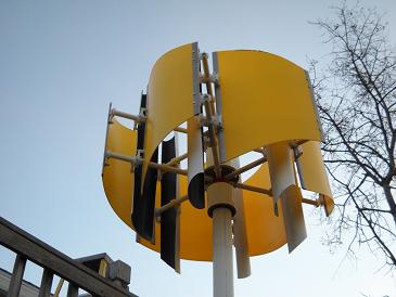
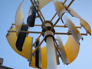
Hi Roe, I have never tried your circuit scheme before and will attempt it the future. The current configuration is each stator is wired as a 3 phase star then the center taps and outputs are connected in parallel. I have to replace my stators in the future because I am using to copper for the size magnets I am using. How do you measure your output? Can you provide any other links that supports your suggestion, I have never seen it before. Thanks for the info. Photos of new blades 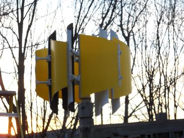
just because your a GURU or forum administer does not mean your always correct :) |
||||
| govertical Guru Joined: 11/12/2008 Location: United StatesPosts: 383 |
It spins just because your a GURU or forum administer does not mean your always correct :) |
||||
| govertical Guru Joined: 11/12/2008 Location: United StatesPosts: 383 |
Hi, just complete the road test. Results using three blades, very bad, startup 25 MPH and 1 amp at 40MPH. Results for 6 Blades,same as the fin style last tested. Conclusion, the fin or C rotor configuration produced the same results. Style of blade will be based on ease of fabrication because they produce the same results for this size blades. I am primarily interested in produce as many amps as possible at low wind speeds, 10 to 25 MPH. I am reducing belt drive gear ratio, increasing blade length, and replacing stators. just because your a GURU or forum administer does not mean your always correct :) |
||||
| govertical Guru Joined: 11/12/2008 Location: United StatesPosts: 383 |
Hi, the drawing I provided is correct but maybe hard to read. I have had some time review your drawing and it appears to be correct. All your coils per phase are connected in parallel and will require a higher RPM to reach 12 volts. My system would never reach that speed. Comments welcome. just because your a GURU or forum administer does not mean your always correct :) |
||||
| Greenbelt Guru Joined: 11/01/2009 Location: United StatesPosts: 566 |
Govertical Hi, My previous post was not clear so I,m trying again. Hope you don't mind that I used your Drawing to illustrate. I still believe your wiring is a much bigger factor than your Turbine or gear box. The resistance through the 8 coil shorted path allows a small current output. all phases are affected.You could series wire the phase coils between Stators to make up the voltage. Remove the Stator connections links, Do a road test with only one Stator to get a good reading of the basic output.to determine the number of series coils needed. Keep on Keeping on. -----------Cheers, Roe 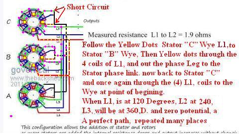
Time has proven that I am blind to the Obvious, some of the above may be True? |
||||
| govertical Guru Joined: 11/12/2008 Location: United StatesPosts: 383 |
Hi, what you are calling a short, is not, it is the center tap parallel connections between all three stators. When I was bench testing this PMA, the way I have it connected now keeps the internal low and provide the best output. What you are suggesting just increases the internal resistance and lowers the output. How do you test your PMA’s? It is not possible for the size blades I am testing with to provide more than a few hundred Watts of energy into the system, I do not see any way that what you are suggesting can increase the output to the kilowatt range. Can you provide any other links to support your suggestion? This is a simple circuit diagram of the PMA. Comments welcome. just because your a GURU or forum administer does not mean your always correct :) |
||||
| Greenbelt Guru Joined: 11/01/2009 Location: United StatesPosts: 566 |
Hi Again GV Time has proven that I am blind to the Obvious, some of the above may be True? |
||||
| yahoo2 Guru Joined: 05/04/2011 Location: AustraliaPosts: 1166 |
If all the stators are perfectly in sync there should be no current flowing along the star centre tap, technically it is connected to the spare diode on the bridge rectifier only as a safety if a field goes open circuit(like a neutral wire), the fact that the resistance is reducing with the 3 stators joined at the star point indicates a fault with the wiring or a stator or rotor is not correctly aligned (out of phase with its mates). EDIT again! This is why god invented clamp meters  I'm confused, no wait... maybe I'm not... |
||||
| govertical Guru Joined: 11/12/2008 Location: United StatesPosts: 383 |
Hi, thanks for taking the time to reply. if you replace the load symbol with a bridge rectifiers for each phase and perform your analysis again, do you still come to same conclusion? The stators have alignment grooves cast into them that saddle the vertical risers. The stators are aligned and the rotors are aligned by the magnets. Can you provide any links supports your analysis? This is a first attempt and a experiment. 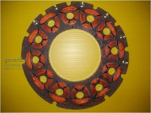
just because your a GURU or forum administer does not mean your always correct :) |
||||
| govertical Guru Joined: 11/12/2008 Location: United StatesPosts: 383 |
Hi Greenbelt, I posted the complete circuit. Can you please show dots again so I can better understand. Thank you for your time and suggestions just because your a GURU or forum administer does not mean your always correct :) |
||||
| Tinker Guru Joined: 07/11/2007 Location: AustraliaPosts: 1904 |
If I were to do this I would not link the three star points (center tap parallel connection in your language) together. Have you tried it without this extra link? Klaus |
||||
| govertical Guru Joined: 11/12/2008 Location: United StatesPosts: 383 |
Hi, yes I have and the output is less. Because I included the connectors for each phase on the different stators I was able to try all the different connection possibilities. The connection scheme shown worked the best. I tested each stator separately in a dual rotor test fixture and found they all had the same output. The stators are ok. When I compare the output results with other projects posted that use the same size magnets the outputs are about the same. There are a lot of misconception regarding VAWT output, people making false claims. The results I am posting are the numbers you can accept from this size VAWT using the same size magnets and stators at the RPM‘s being produced by this blade configuration. The test results have indicated that the blades need to much larger . If you want a 500 watt VAWT you should design 2 K and after Betz’s limit and all the other system reductions you would than have a 500 watt unit. just because your a GURU or forum administer does not mean your always correct :) |
||||
| Greenbelt Guru Joined: 11/01/2009 Location: United StatesPosts: 566 |
Govertical One third of each phase cycle is neutralized by the presence of voltage on the common, This small voltage will cause current to flow through both stator phase coils in the load bypass to the phase 1 coils. With out the bypass no current could flow to cause a magnetic field to oppose the phase following. When phase one is max volt, phase 2, mags approach the coils and are at 1/3 max potential, the reverse polarity at this time will prevent phase 2 from contributing any useful current. when phase 2 passes 180 degrees to 240 degrees the polarity would be correct for phase 2, but the voltage on phase 1 does not reach zero until 180 degrees. this means that phase 1 will affect phase 2 from 120 deg. to 180 deg. And because one phase follows the one before in a uniform sequence to eternity, all phases are compromised. I Believe a Four foot anything would produce more than a hundred watts at 60 miles per hour. so I believe your machine can do better. I commend you for trying to find a means to lower resistance in the generator circuit but it is unlikely that you will succeed without superconductors. The lower resistance you are reading is due to 9 parallel paths through the coils of 3 Stators. If anyone wishes to correct my ramblings, Speak up, else I'll go on harping about something I know nothing about. Make 3 stand alone stators with their own diodes and connect them at the battery post. with an isolation diode just in case a bridge fails, this will save your battery charge and maybe the Gen. Good Luck. I'm still watching this thread, especially like the machine work you do. ----------------------- Cheers Roe Time has proven that I am blind to the Obvious, some of the above may be True? |
||||
| govertical Guru Joined: 11/12/2008 Location: United StatesPosts: 383 |
Hi, I have no connection between the battery(-) to the PMA center tap. When there is no connection the PMA acts as a current source. How do you connect the PMA to the batteries? just because your a GURU or forum administer does not mean your always correct :) |
||||
| govertical Guru Joined: 11/12/2008 Location: United StatesPosts: 383 |
Image of system connections just because your a GURU or forum administer does not mean your always correct :) |
||||
| govertical Guru Joined: 11/12/2008 Location: United StatesPosts: 383 |
Hi Greenbelt, I found a tutorial on how to connect a PMA to a battery bank. http://www.thebackshed.com/Windmill/articles/Rectifiers.asp connections for PMA to battery bank Does this change your nodal analysis? Yes the lower resistance is a result from the 9 stator parallel connections. As I added more stators the cut in RPM reduced by 100 RPM for each stator I added. I am curious have you ever built a working system using your wiring method? I am still learning, thank you for taking the time to explain your point view. just because your a GURU or forum administer does not mean your always correct :) |
||||
| Greenbelt Guru Joined: 11/01/2009 Location: United StatesPosts: 566 |
Govertical Read every paragraph---A C E Coil Leads ------Cheers, Roe Time has proven that I am blind to the Obvious, some of the above may be True? |
||||
| govertical Guru Joined: 11/12/2008 Location: United StatesPosts: 383 |
Hi, that shows no common connection between the load (battery) and the stator also. Have you fabricated a working system using your wiring method????? The diagram described is for a radial flux with over lapping coils. It looks like you are redrawing my diagram to illustrate a problem when there is no problem. just because your a GURU or forum administer does not mean your always correct :) |
||||