
|

|
Forum Index : Electronics : Inverter building using Wiseguys Power board and the Nano drive board
| Author | Message | ||||
| KeepIS Guru Joined: 13/10/2014 Location: AustraliaPosts: 1679 |
For anyone wanting a programmer for uploading the Inverter Hex file to the Nano: The Arduino IDE supports these small programmer boards. But you are better of using a very simple program which I have posted about before, set up and ready to go. Using the Arduino IDE overwrites EEPROM each time - yes I know it can be stopped, but it's not worth the bother and this is a "keep it simple" post for builders new to burning micro Firmware. You don't even need the hassle of installing the Arduino IDE with this tiny program. Xloader This is the programmer I use. I tested it against a much more expensive board that promised fast speed - but alas NO - This $15 unit is twice as fast. Core electronics AU. Jaycar - Looks the same The only issue is the supplied lead has to modified to plug into the Nano header, the Header on the Nano board is 6 pin The programmer board has the Standard 10 pin. I made one up, but also found this adapter, this makes easier for some of us: Jaycar Adapter Potostack AU Any questions, clarification, comments, help or other sources of low cost programmers welcome. . Footnote added 2024-06-08 16:39 by KeepIS I posted the wrong program information: Xloader only works for a Nano with a boot loader and not with a Hex File. The correct program is AvrDudess to burn the Hex File. I have uploaded an updated stand alone version with a Screen shot of the setup. AvrDudess zip It's all too hard. Mike. |
||||
| KeepIS Guru Joined: 13/10/2014 Location: AustraliaPosts: 1679 |
One thing I forgot to mention when using a LM7805 regulator, it requires a 0.1uf across the output and a 0.33uf across the input, I always solder these across the Regulator pins on the bottom of the board, there is room for a small 220uf or 330uf on the output side, two mounting holes are available on the board. I'm sure Mike (WG) will advise you on his preferred mounting, components and layout in his Thread. . It's all too hard. Mike. |
||||
| KeepIS Guru Joined: 13/10/2014 Location: AustraliaPosts: 1679 |
A final DSO image of the 5v rail as inverter is powering down. Test caps I had on the LCD plugs are of course removed. I removed the Controller, added a small 1000uf to the output of the 7805 linear regulator, and added a 220uf to the input (across the 12v). Both simply solder into the existing holes next to the 7805 very neat, no mods, no tracks touched. If you get a small SMPS regulator this clean then go for it, but if not, I think the simple 7805 change and the supervisor IC mod will give you all the peace of mind you are seeking.  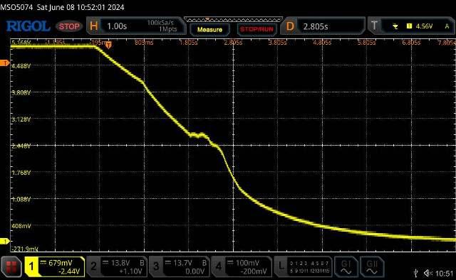 . It's all too hard. Mike. |
||||
| KeepIS Guru Joined: 13/10/2014 Location: AustraliaPosts: 1679 |
FYI: I have added a footnote to a post on the Programmer board for Hex files. I'll repeat it here in case it's missed: Xloader only works for a Nano with a boot loader and not with a Hex File or programmer board. The correct program to upload a HEX file is AvrDudess. I have uploaded an updated stand alone version with a Screen shot of the setup and the config file should be ready to go, you just need to point the program to the hex file. AvrDudess zip EDIT The security message when downloading is a complaint that the Site is HTTPS but the download location is a HTTP location (not secure site). This is crap as it's from my site, the same site as the HTTPS page, this file is an FTP download - seriously! . Edited 2024-06-08 18:28 by KeepIS It's all too hard. Mike. |
||||
| KeepIS Guru Joined: 13/10/2014 Location: AustraliaPosts: 1679 |
FYI: I removed both the Reset control cap and USB +5v supply diode between the onboard USB micro interface and the Nano Micro. The USB controller and Nano are now only powered only from Controller +5v, this is the normal running state for the Nano module without a USB connection. I placed a clip-on ferrite choke with 2 turns of the USB lead through it and bought it out to a USB socket on the Inverter cabinet. I can now safely plug and unplug a USB connection to a Laptop or PC without any possible impact to the running Nano controller. So, screw anything that thinks it has the right to control my Inverter Nano - except me. What was that favorite slogan of mine - oh yes, "I will NOT comply"  . It's all too hard. Mike. |
||||
| KeepIS Guru Joined: 13/10/2014 Location: AustraliaPosts: 1679 |
This may be of some interest from bits and pieces of random searching: It appears that BOR has two options. 1: Somewhere between 2.5 to 2.9 volts - This voltage is fixed and depends on device tolerances. 2: 4.0 to 4.6 volts - As above The brown-out detect voltage has hysteresis to ensure spike free detection, typically around 80mv. The 1.8 volts I mentioned appears to be Power On reset voltage when the reset pin is tied to VCC, and not Brown out reset as I had read in forums. This can be, and is, obviously disabled in these boards. Further reading indicates that these Nano chips are designed in two variations. A Rugged Motor Vehicle version with ESD protection etc, and a lower cost version we use does without? Either way, I feel it indicates that the Core design is sound and has a lot of history. I think I've found a source for the full data file, about 10Mb long, I just can't access the some sites at the moment, and this is one. . It's all too hard. Mike. |
||||
| wiseguy Guru Joined: 21/06/2018 Location: AustraliaPosts: 1156 |
I moved this to where it belongs in my thread sorry Mike Edited 2024-06-09 15:23 by wiseguy If at first you dont succeed, I suggest you avoid sky diving.... Cheers Mike |
||||
| KeepIS Guru Joined: 13/10/2014 Location: AustraliaPosts: 1679 |
For anyone interested in freeing the Nano Micro from the control influences of the USB port. I have two, not very good photos, of a couple of Nano boards I have. The Diode removed did the following: Isolated USB +5V from the Nano board to stop 5V back feed out through the USB port, and it allowed the USB +5v from the PC to feed the Board (Nano) at all times. Removing the Diode is not a problem, we are using a small programmer board that also powers the Nano during programming via the 6 pin header. Removing the Reset Cap between the Nano Reset pin and the USB micro / USB port, disables the USB micro and anything on the USB port from resetting the Nano controller (Inverter). Again, this USB Reset control is not needed when we program the Nano board using the small programmer board. With these removed and with the automatic removal of the Boot loader when you program the Nano with a programmer board and Hex file - makes for a really robust little board. The USB port, when connected to a PC or Laptop, is used for setting up the operation parameters of the Inverter via the Setup Menu, it still functions perfectly. Board 1 with an FT232RL USB controller. 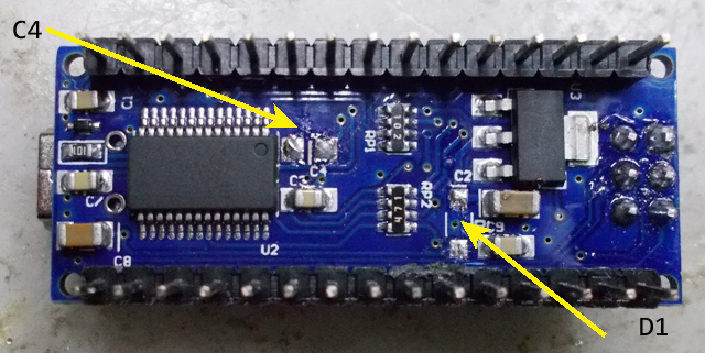 Board 2 with a CH340 USB controller. 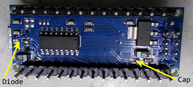 The small programmer board in conjunction with the small standalone program handles HEX file uploads and more. . It's all too hard. Mike. |
||||
| KeepIS Guru Joined: 13/10/2014 Location: AustraliaPosts: 1679 |
This is a Nano I've had for around a year, it's from Keyestudio, a bit expensive though. Th first one I've seen with a crystal next to a CH340 USB controller. The mod is similar to the previous posted Board 2. I posted this somewhere else but I'll repeat it here. I finally downloaded that file I was after and it only gives two BOR options, the lower voltage setting is marked as reserved. The Nanos I have checked are set to Mid setting of between 2.5 - 2.7 range. I will go through the other clones when I add the headers. The lowest setting is marked as reserved. (No 1.8v option shown) I have to say that using the small Programmer with a modified Nano is actually nice because: When writing code in the Arduino IDE and then uploading it to test, requires any other program using the Com port, like a Console Terminal program to be disconnected, after the upload has finished, it has to be reconnected again. It does not sound like much, but after a while it grinds on me. Using the Programmer with AvrDudess allows you to point this program to the compiler output directory used by the IDE. So I build-verify the code in the IDE as normal, then Press Upload in the AVR program window and it's done. Yes you can do this with the IDE, but there are options available to speed the upload up which are not available in the IDE - you can go behind the scenes and make edits, but what a PIA. The big advantage is that the USB port on the Nano is not used to program, it remains connected the the Terminal Coms program, and debug or other output streams to the Terminal program when the upload is finished. . It's all too hard. Mike. |
||||
| KeepIS Guru Joined: 13/10/2014 Location: AustraliaPosts: 1679 |
I decided to go back and check the Ground plane on my Big Inverter, this has been running The Nano controller for a few weeks 24-7, we are only on mains when I do some Modification to the Inverter. About a week ago, one of those modifications was to add Ferrite beads to the Power board and fit a 15V isolated module to enable -3v gate bias, and also halve the value of the Gate resistors. Today I revisited the Ground plane installed with the Previous controller board. Checking the interference on the board was pretty good, but what I hadn't had a chance to do was check the level of noise on the incoming leads, well this time that was a bit eye watering. This has Nothing to do with the Nano Controller or the Power board, it has been a "sometimes" overlooked problem with previous inverter builds going back to day one. The way the Controller board is designed with a ground plane setup in mind is new to most DIY inverter controllers. The noise on the connectors CON6 Pins 2,3,4,5 (LEDS) and J1 pin 1 Inverter Off, was a few volts of fast transients. Basically any wire running through the inverter and coming back to the controller can bring some noise with them. I tested a 0.1uf across the offending pins and all responded. Some pins should have a much smaller value around 0.01uf for discharge / timing reasons. Note Do not bypass Sensor leads (AC VFB or Current Sensor) with the exception of the Thermostats, where I used a 0.01uf. I removed the controller board, fitted suitably voltage rated bypass caps from the Sockets Pins under the board to ground and retested. This was easy to do and worth the effort, noise came down into the 50mv P-P region. My 48V supply input is quite clean and did not need a bypass, a couple of connections already a 0.1uf near the pin. Another result was a slight Idle offset that I had on AC current dropped by half. All readings were taken with respect to the Controller board ground, I have a pin that I fitted to controller board for testing. Do not connect anything (I mean test lead ground clips) to the ground plane! I hope the above makes sense.  . Edited 2024-06-10 19:23 by KeepIS It's all too hard. Mike. |
||||
| KeepIS Guru Joined: 13/10/2014 Location: AustraliaPosts: 1679 |
Someone asked about reclaimed memory after removing the Boot Loader. This is for the Optiboot loader in the Nano 328, other boot loaders vary. The amount of memory reclaimed by not having the boot loader is 2048 bytes, a program using 75% of program memory would be now compile to 70% of used memory without the BL. It's all too hard. Mike. |
||||
Revlac Guru Joined: 31/12/2016 Location: AustraliaPosts: 1023 |
I checked most of the Nano's I have and they are the same as Board 2 with a CH340 USB controller. Will have to find the 6 pin headers... on the bench or floor or something.  I will probably mount the control board further away from the inverter and the wiring if that helps.  Cheers Aaron Off The Grid |
||||
| KeepIS Guru Joined: 13/10/2014 Location: AustraliaPosts: 1679 |
Yes it will, you will notice with my inverter I went for a large cabinet with elbow room around everything - sure makes upgrades, mods or repairs easy. The controller board is only around 100mm from the power board, but side-on and is mounted on a Ground plane. Most cables come in from above the Controller, which is the DC input and control compartment, Toroid and chokes are some distance below the Controller board and offset. I know you like to build them big - you should have no trouble. As you know, the 6 pin headers can be cut out of larger pin header strips, like the ones used on the Nano IO ports, I usually buy 40-pin strips 20 at a time, very low cost that way. FYI: There is a very simple way for Nano controller builders to save their current settings and then reload them if they ever loose them. Or in my case, have separate files for more than one Inverter. Everything gets simple with the Little programmer. Uploading a new HEX file does not overwrite the existing EEprom settings, but it's still nice to have them backed up after going to all the trouble to get them just right. . Edited 2024-06-11 19:35 by KeepIS It's all too hard. Mike. |
||||
| KeepIS Guru Joined: 13/10/2014 Location: AustraliaPosts: 1679 |
I though I'd attempt to show the following for anyone new to the Arduino Nano: 1: Program uploading - Hex file. 2: Backing up your Inverter and Calibration settings. 3: Restoring those setting. 4: Removing the Boot loader. 5: Reading and Setting Bit Fuses. Not all in that order. There will be a few separate posts - please bear with me until I post the last, then we can pick it to pieces. Post 1: Starting with a New Nano with a preinstalled boot loader: We are going to remove the boot loader, this also unlocks the protect fuses, which the boot loader keeps resetting until it's removed. There are two ways to do this, both are simple, but the following has less steps and also gets the HEX Code file programmed in one go. To do this, we are going to simply upload the inverter code HEX file, erasing flash at the same time. This is the screen of AveDudess - I have previously posted Links to this and will do so again at the end of the posts, this is the standalone, no install version. There are drop down lists with 100 odd Micros and Programmers: I have edited Setup and selected just a few: You can click the Setup button and add or remove items from the Lists as you please. Simply press the little button at the end of the Flash code file line [...] and select the HEX file to upload to the Nano. The image below is how the program settings should look. When ready to program, Press Program! The output should look like the bottom black output window in the image below. 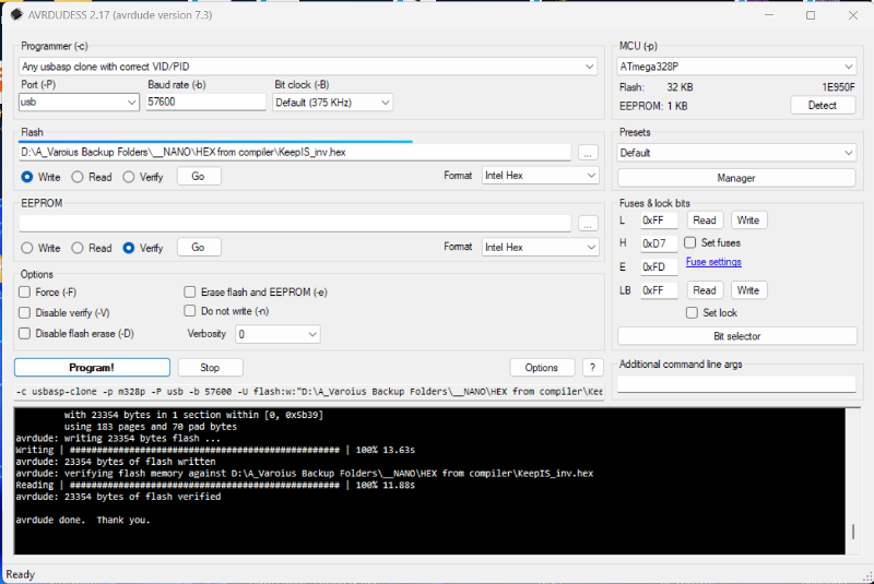 After uploading the Hex file: 1: Press the top "Read" button under Fuses & Lock bits" 2: Press the long button "Bit selector" The Top line in the pop up window "Lock Bits" should not have any Blue tick boxes, especially BLB12, BLB11. These were the Boot block enable bits (see next post). It's all too hard. Mike. |
||||
| KeepIS Guru Joined: 13/10/2014 Location: AustraliaPosts: 1679 |
2: Setting and Reading the Nano configuration Fuses: Nano Fuses are "programmable nonvolatile registers", one is used to stop EEprom data "Inverter settings", from being overwritten, "lost" when Nano Flash is erased or when uploading New inverter HEX code to the Nano. 1: Press the lower Read button on the "Fuse & lock bits" frame. 2: Press the long "Bit selector" button. See Last post for the location: The following image is likely what you will see for a New Nano board. The two blue boxes BLB12, BLB11, are the boot loader protect bits. They stop that area of Flash memory from being overwritten when uploading standard Arduino code files via the boot loader and USB port in the Arduino IDE. Below: New Nano with boot-loader Config bits. 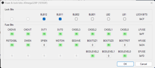 Below is what we want the bits to look like. 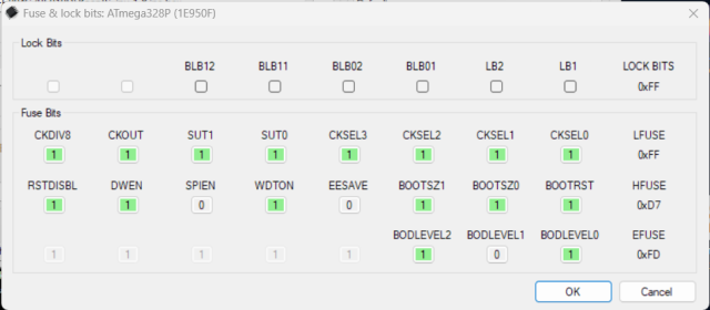 Now, there is something strange going on when reading and setting these Bits but doing the following works. 1: Read the Top "L" block 2: Set the Bit boxes to look like the last image above. 3: Press "OK" to close the popup window. 4: Press the Top write button. 5: Press the Lower "LB" write button. Now repeat with the lower block 1: Read the Lower "LB" block. If it EESAVE is not equal to 0, do the following: 2: Set the Bit boxes to look like the last image above. 3: Press "OK" to close the popup window. 4: Press the Lower write button. Now confirm both read the same. The Main setting we really need correct is EESAVE "it must be 0" Saving and restoring Inverter configuration and setup to follow . It's all too hard. Mike. |
||||
| KeepIS Guru Joined: 13/10/2014 Location: AustraliaPosts: 1679 |
Backing up the Nano inverter settings: Once you have setup the Inverter and calibrated inputs, It is a good idea to backup your settings just in case, a lot easier then having to re-calibrate and set everything up again. Below is the setup screen we used to upload the Inverter HEX file. Select the round "Read" option in the "EEPROM" frame. 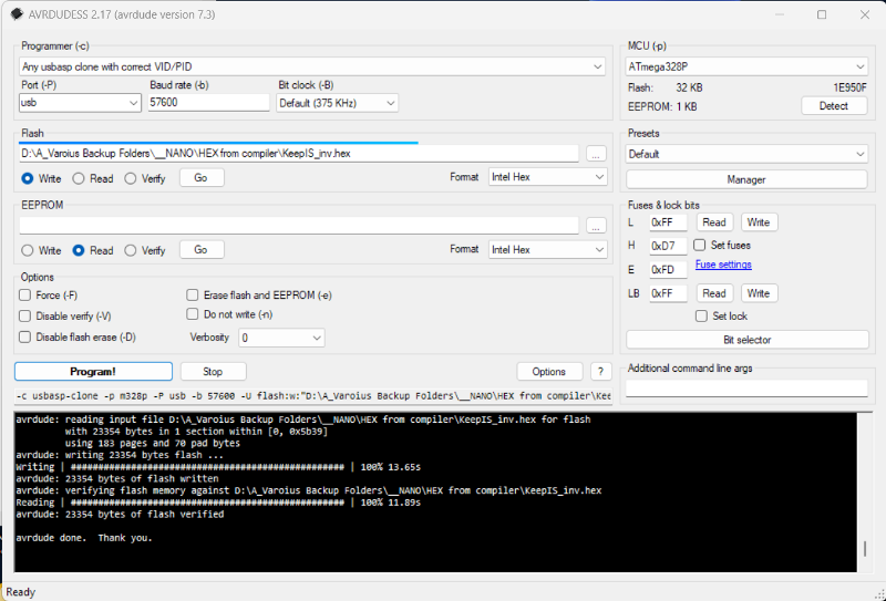 When you Click on the [...] button at the end of the EEPROM file line, you will open a window something like the following: If a file exists it will be overwritten, type a new file name and it will be created when the EEprom from the Nano is read. 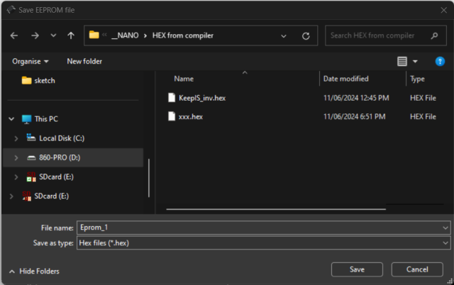 To Backup: Press the "Go" Button below the EEPROM Backup File entry line on AVRDUDESS. It's surrounded in a blue border in the Image below. This is what you should see after an EEprom read / backup, check the Black output window at the bottom. 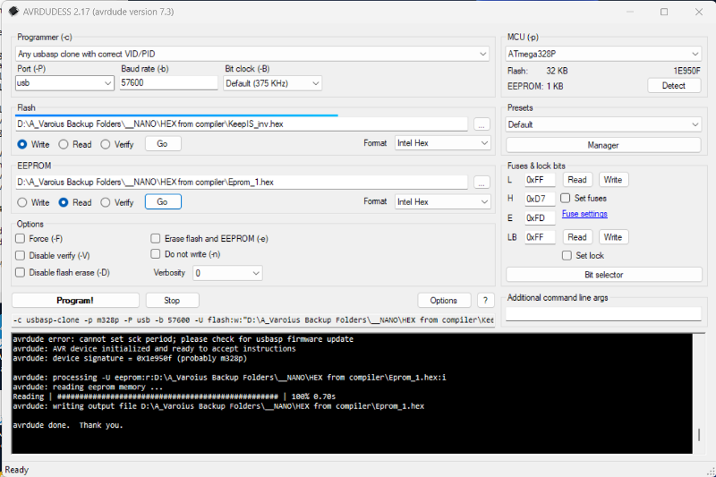 Below: To restore The Inverter backup EEprom file: Same as above but Select the File to restore from, select the "Write" option below the File name line, press the "Go" button. 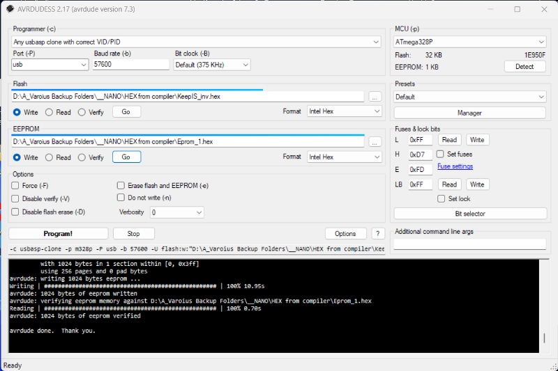 Restoring EEprom configuration Data does not affect the Main Code in the Nano. Once restored you should delete the File path in from File line, this stops any accidental writing or reading to the EEprom or your Backup file. Note: The format selection below the end of each File entry Line must always be HEX. . Footnote added 2024-06-12 18:12 by KeepIS Correction Under the first Image: You may have to use your chosen Directory viewer and create a Directory to keep the EEprom backup files in, then create an empty text file with a .HEX extension IE: "EEbackup.hex" in that directory. Load that file into ARVdudess for you first EEprom backup. That file will be overwritten when you "Read" the EEprom. From then on the ARVdudess program will remember that directory path and file name. To makes another backup file, just select the same file and change the file name in the EEprom file name line in Avrdudess. I hope that makes sense. . It's all too hard. Mike. |
||||
| KeepIS Guru Joined: 13/10/2014 Location: AustraliaPosts: 1679 |
Please let me know if I've screwed anything up here, or if there is something more you think others would like covered. I swear when I see errors I somehow convert them in my mind and then I don't actually see them  For anyone wanting to play around with the Nano PCB and the small programmer: Here is a link to my Hex program. Hex Code ZIP file. You can change Settings and reprogram to verify for yourself that EEprom is still valid and settings don't change when uploading Hex Code. Here is a link to the Program used in the How to Nano posts. The AvrDudess program Anyone trying to download, pleas tell me if you get any error at all, with the download operation !!! EDIT: The last Line in the previous post should read "Intel HEX" BTW I found this from Microchip: Brown-Out protection: "Note that AVR ® internal Flash Program Memory contents are never affected by insufficient power supply voltage." The EEprom can be corrupted (inverter settings) if BOR is removed. The main reason reported for removing the boot loader - During some brown out conditions, the Boot loader will try to start/stop and could corrupt your Flash program memory. . Edited 2024-06-12 16:27 by KeepIS It's all too hard. Mike. |
||||
| -dex- Regular Member Joined: 11/01/2024 Location: PolandPosts: 99 |
Briliant!  |
||||
| KeepIS Guru Joined: 13/10/2014 Location: AustraliaPosts: 1679 |
For anyone interested, I have added a basic Menu settings info PDF to the hex download zip in my last post. Menu text has been cleaned up and Menu setting entry fields reworked. More junk, I mean parts. Next door having a new solar system put in, I manged to grab the old inverter. Solaredge SE4000 The black rectangle boxed are large isolated transformers, I suspect High voltage, I wondered why it was so heavy - weight is like a Toroid. Thing is in perfect working order, good for a few parts and the case is perfect for a backup inverter very large case with huge heatsink, all thick aluminum, a toriod and power board will fit in easily. . It's all too hard. Mike. |
||||
| Murphy's friend Guru Joined: 04/10/2019 Location: AustraliaPosts: 648 |
Just the thing for GTI back charging, good find  |
||||