
|

|
Forum Index : Electronics : Builiding of a complete 6kW PV inverter with MPPT chargers
| Author | Message | ||||
| -dex- Regular Member Joined: 11/01/2024 Location: PolandPosts: 99 |
Thank you for the detailed explanations and pictures  I had to go out for some fresh air, run a bit with my son - not much older than your little assistant. I did what was suggested. The aluminum plate was connected to earth bus and a 10nF/100V MLCC capacitor was added Edited 2024-06-10 05:05 by -dex- |
||||
| -dex- Regular Member Joined: 11/01/2024 Location: PolandPosts: 99 |
And now the good news - with the same load there is now no voltage drop!!! With this resistive load (the same ~2kW kettle, also used previously), it increased the AC voltage even slightly, and the % SPWM change was also visible. I probably need to put even more load in there now before I open the bubbles, but at this point feel how much I'm shaking your hand in gratitude for your help Mike! 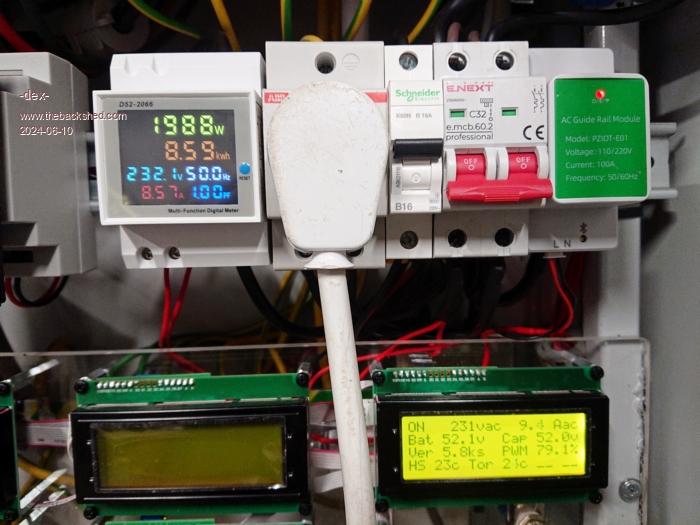 |
||||
| wiseguy Guru Joined: 21/06/2018 Location: AustraliaPosts: 1156 |
That is great news Dex, to be honest I woke up after a very sleepless night with a sense of dread, thinking what if it does not fix the issue, now what. You see after I posted, that I could account for maybe a 1.8% change not 7.2% I went to the workshop and started my inverter and tried to inject noise into both input pins of the opamps U1A & B and U2B. The only pin that I could make a small change with was U1B pin6. But I even got a clip lead and coupled capacitors direct from the switching node before the chokes using 2.7pf all the way up in small increments to 100pf but I could not cause the amount of change you were experiencing. In hind sight my inverter was unloaded whilst I was doing all this so it wasn't exactly the same test I suppose - that was when I started doubting myself. I don't want to boast but when you bought those boards for the inverter you also bought 40 odd years of experience and cunning with it, I consider analysing servo loops and noise injection and curing issues with them to be two of my specialties. I have fixed some amazing things in my career that other engineers gave up on, sometimes just shifting a wire to a different point on the same track solved problems. The secret is turning differential noise into common mode noise and the problems magically vanish, all the way up to RF. The provision of the pads for the 10n cap insertion was my typical belts and braces approach is it possible this may be required ? - better to have it and not need it than the other way around. Anyway thanks for working with me and happy invertering ! I have a confession I did the drawing in a hurry with my mouse using microsoft paint and the mouse freehand. It reminded me of trying to use an etch O sketch if you know what that is lol but I was otherwise engaged and had no time  Edited 2024-06-10 10:11 by wiseguy If at first you dont succeed, I suggest you avoid sky diving.... Cheers Mike |
||||
| -dex- Regular Member Joined: 11/01/2024 Location: PolandPosts: 99 |
You need to try using a noise injector like mine in the photo below  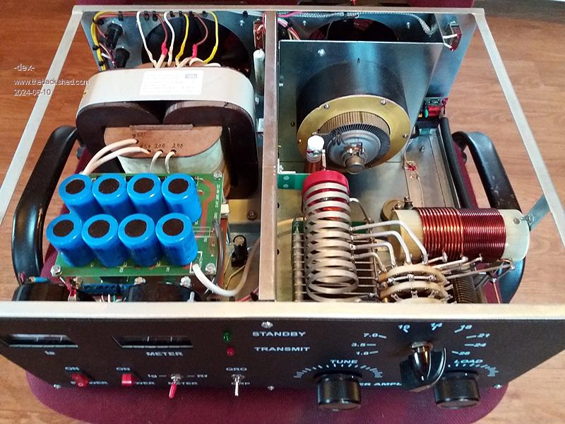 Just kidding, I haven't done it this way with these lamps, but someday I will make such tests and I hope that the inverter will remain insensitive to the advances of strong radio waves. Returning to the AC regulation system - now I see that the servo is working fast, because I constantly observe subtle changes in the AC voltage after the decimal point, ie didn't do that before. Moreover, I have the impression that there is a tendency to slightly increase the AC voltage under load - is this the result of my EMI filter? I calculated that the total impedance of the filter coils at the 50Hz is approximately 0.43Ω, does the nano see the AC voltage drop and try to increase it? While we were talking about chokes, toroid capacitor, and the overall appearance of the wave, someone here suggested me using a metal-cased EMI filter, so I put it there. From memory I didn't notice any effect on the wave, but it remained there. Are there any benefits with using EMI filter on the toroid output? |
||||
| wiseguy Guru Joined: 21/06/2018 Location: AustraliaPosts: 1156 |
That sure is a scary looking piece of equipment - I think I will stick to inverters. Is that a type of magnetron ? It sure is a complicated looking pie warmer. Is that actually MHz on the tuning scale? Now to the mains filter. I would not put it there personally I would connect it at the exit point where the Mains exits your cabinet, it will better filter inverter and MPPT noise on the external mains wires. It should not matter about its impedance where it is, as it is in a servo loop, so the inverter regulates to wherever the sense wires are connected after the filter, as you have it set up. I prefer to have the voltage sense feedback wires connected direct to the toroid winding. As far as a bit of droop after the Filter at the final output, which the inverter wont know about, I say ignore it. Ok so the light might slightly flicker when things turn on or off not much different to the street mains supply in most cases. As far as the voltage increase goes I suspect that if you measure at the sense wires for loaded and unloaded the readings should be the same. If not it might be due to an imperfection in the "precision rectifier", as it is an AC Peak not an AC RMS circuit, so if there is any distortion of the sine wave it will not be a perfect result so a minor change of a volt or so can be ignored. Before you relegate the chokes to the waste bin you should find my earlier communication I dont remember the exact details but thought was it 11 turns would be good but you used 13 (I think those were the numbers) so reducing the ampere turns a little will help reduce the heat a bit. Anyway hope it is performing to your expectations now. To help reduce radiated noise from the inverter I would find 2 x 4,7 - 10n capacitors of at least 250VAC rating and place them at the 2 nodes where the chokes connect to the toroid (27VAC?) and the other end of the Caps to chassis ground. Place the caps as close to the chokes as convenient, that should help tame some of the harmonics of the fast switching FETs. Maybe your radio might suffer less. Edited 2024-06-10 19:40 by wiseguy If at first you dont succeed, I suggest you avoid sky diving.... Cheers Mike |
||||
| -dex- Regular Member Joined: 11/01/2024 Location: PolandPosts: 99 |
Currently, there is one layer of copper tape, the cross-section of which is ~10 mm2. 10 minutes of operation with a 2.5kW load causes the temperature to rise to 70 - this is the data I read from the inverter (it has an NTC thermistor on it) I tried this already before, I used 2 layers of the same tape for one choke, but then the inductance was too low and the cross-section was also not impressive. This is because I can't squeeze anything else in there. That's why I decided to build new coils that will solve the choke's problem once and for all - I hope  I ordered toroid cores made of sendust material, large enough to fit enough turns to obtain 22uH with using 50mm2 cable. The current E-core coils won't go to waste - I'll definitely use them in another project  |
||||
| -dex- Regular Member Joined: 11/01/2024 Location: PolandPosts: 99 |
Currently, there is one layer of copper tape, the cross-section of which is ~10 mm2. 10 minutes of operation with a 2.5kW load causes the temperature to rise to 70°C - this is the data I read from the inverter (it has an NTC thermistor on it) I tried this already before, I used 2 layers of the same tape for one choke, but then the inductance was too low and the cross-section was also not impressive. This is because I can't squeeze anything else in there. That's why I decided to build new chokes that will solve the choke's problem once and for all - I hope  I ordered toroid cores made of sendust material, large enough to fit enough turns to obtain 22uH with using 50mm2 cable. The current E-core coils won't go to waste - I'll definitely use them in another project  Edited 2024-06-11 21:25 by -dex- |
||||
| Murphy's friend Guru Joined: 04/10/2019 Location: AustraliaPosts: 648 |
You seem to go from one extreme to another with your choice for choke copper cross section. 10mm sq is obviously too low and 50 sq mm sounds rather generous to me (good for 200A continuous, conservatively) Why not compromise, use 35mm sq and try to up your inductance? You can fit more turns by using parallel strands of enameled copper wire. Try 42 -49 strands of 1 mm diameter, thicker wire gets harder to wind onto a stack of those Sendust ring cores. I like to twist 7 strands initially to make individual 7 strand enameled wire cables. Then wind 6 or 7 of these the calculated number of turns around the core and connect all in parallel. There is an online calculator to find out how many 7 strand cables will fit in your core hole - this lets you know how many tuns will fit. Try not to squeeze in too many turns or the last one will be difficult to pull through. |
||||
| Murphy's friend Guru Joined: 04/10/2019 Location: AustraliaPosts: 648 |
Turns to fit into hole calculator: www.engineeringtoolbox.com/smaller-circles-in-larger-circle-d_1849.html |
||||
| wiseguy Guru Joined: 21/06/2018 Location: AustraliaPosts: 1156 |
Hope the new choke works out great! Edited 2024-06-11 22:13 by wiseguy If at first you dont succeed, I suggest you avoid sky diving.... Cheers Mike |
||||
| KeepIS Guru Joined: 13/10/2014 Location: AustraliaPosts: 1679 |
Hi Mateusz, slightly off topic and back to the picture of that beautifully made little Linear you posted, did you build that or is it something made over there. Really nice either way. It's all too hard. Mike. |
||||
| kevinbacon Newbie Joined: 21/12/2023 Location: AustraliaPosts: 2 |
Wow, that inverter looks awesome. Nice work. I'm presuming the cable you've used is equivalent to something like this? |
||||
| -dex- Regular Member Joined: 11/01/2024 Location: PolandPosts: 99 |
I did it with single wires in the case of MPPT chokes. 49 strands would be a challenge  I wind using to the welding cable, even the thick one is flexible enough to be twisted. It is handmade but not mine, a small Ukrainian factory. GU74B lamp Yes, it's probably the same as my wire that was used to wind the toroid. I definitely do not recommend the cable you see in the post you quote. |
||||
| -dex- Regular Member Joined: 11/01/2024 Location: PolandPosts: 99 |
New power chokes By winding 13 turns, I obtained 25uH for a single choke. The saturation current is at least 310A. There is still some space there, but I didn't have enough wire - in practice, one turn was more than calculated. The cable is the same as on the toroid transformer - 50mm2. They are certainly more than adequate for current applications. But who knows, maybe one day I will dare to more extreme power tests  Now the chokes do not heat up like the previous ones. They have one more advantage - they are super quiet. The previous ones on the E core, even though they were glued together, produced squeaking and sizzling sounds. Here are the cores, controller board for size reference. NEW EMS CORE 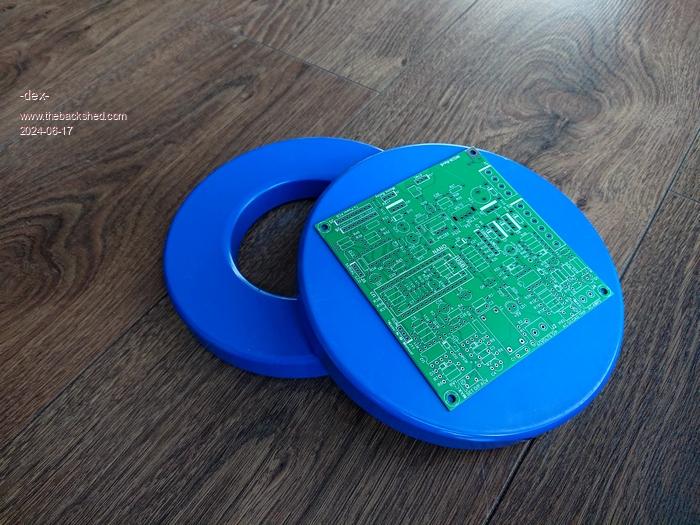 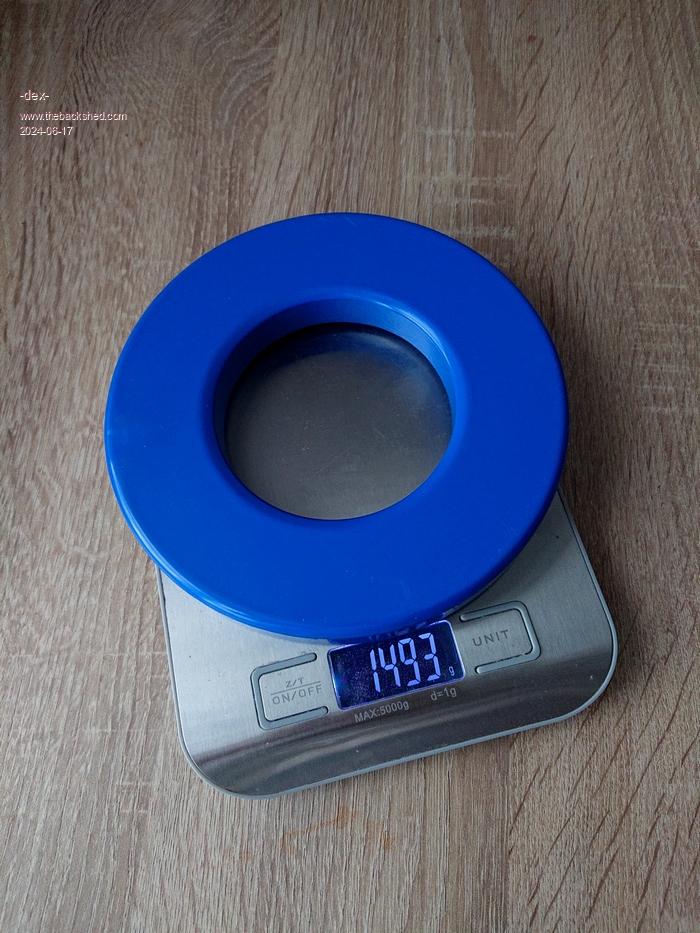 Edited 2024-06-17 18:33 by -dex- |
||||
| KeepIS Guru Joined: 13/10/2014 Location: AustraliaPosts: 1679 |
Very nice, and the inverter sounds so much better when you have silent chokes and no core heating, just a little cable R-loss heating at high power.  A couple stacked would be good for really high start loads, but they are a bit on the expensive side over here. . Edited 2024-06-18 13:09 by KeepIS It's all too hard. Mike. |
||||
| -dex- Regular Member Joined: 11/01/2024 Location: PolandPosts: 99 |
Setting up OCP The inverter current sensor was initially calibrated to approximately 6kW of power. In such a configuration, starting any power tool (saw, hammer) or a larger SMPS power supply activates the OCP and forces user intervention to restart the inverter. The overload detector is very fast and sensitive. Mike advised setting the current sensor value to twice the current of the mechanical fuse breaker. In my case, the AC breaker at the inverter output is 32A, so for calibration we need 64 AC on the current sensor. There is a simple trick here - wind 10 turns on the current sensor, then you need to get 10x less current. I did it using an 8ohm resistor and a toroid transformer whose voltage I selected to obtain a current of 6.4A (I don't have a variac) Now all you need to do is set the RV2 potentiometer in the right place. The adjustment range is sufficient. The TEST MODE was very useful here - there is no need to remove the board, and you can adjust the overcurrent with the inverter turned off. I don't want make an intentional short circuit on the AC side for testing purposes to see if it works I mean whether the first mechanical fuse or the OCP inverter will trip, if at all  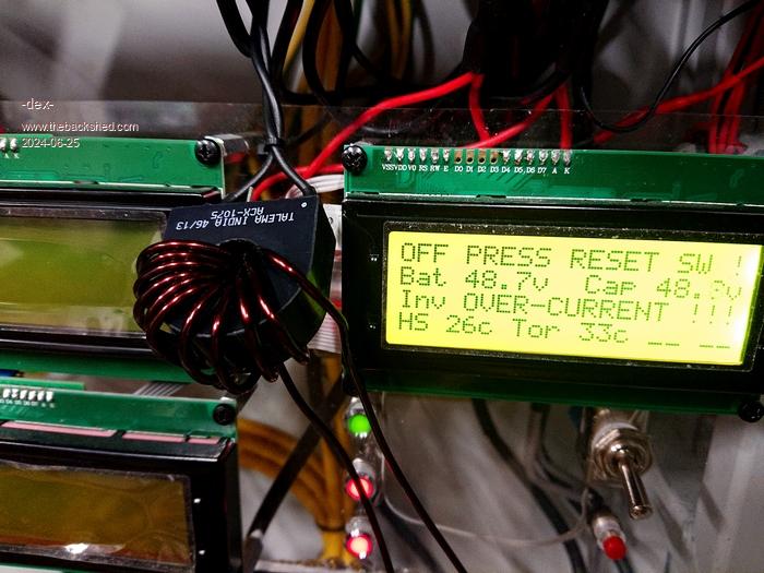 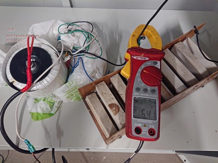 Edited 2024-06-25 22:54 by -dex- |
||||
| wiseguy Guru Joined: 21/06/2018 Location: AustraliaPosts: 1156 |
In the picture of the current sensor it appears that the copper wire passes 11 times through the centre hole of the current sense transformer ? Unless it is an optical illusion, it means that your max current trip is now actually 10% higher than you were trying to set ? How is your inverter running, do you see any flicker of your room lights when a heavy load is switched on or off? Do the Fets or Toroid get very warm under tests so far? I believe your chokes are a total of 60uH, I would have thought that as per all of KeepIS's testing that a value around 40-45uH is probably closer to the mark. In my experience too, more inductance is not actually better, whilst a larger value might make the 50Hz "cleaner" and a lower idling power, it may not be best suited for larger loads. The slight ripple observed on the mains output with smaller chokes should not cause any issues with the load, you only have to look at normal mains and the crap supplied with the fundamental 50Hz from the grid. If at first you dont succeed, I suggest you avoid sky diving.... Cheers Mike |
||||
| Murphy's friend Guru Joined: 04/10/2019 Location: AustraliaPosts: 648 |
I too counted 11 turns (1 turn = 1 pass through the hole). This concept was also new to me back when warpspeed explained the reason why it is so  . . |
||||
| -dex- Regular Member Joined: 11/01/2024 Location: PolandPosts: 99 |
I understand one turn as one complete loop around the core. I also use this with the chokes. The 25uH I provided refers to the value I measured using an oscilloscope. There is definitely some measurement error there, but could it be several uH? As for temperatures - the toroid all the time is slightly warm, during operation the temperature does not exceed 40°C. Temperature on heatsink with fets is in the range of 30-37°C. Everything is closed in one common cabinet, toroid and fets heatsink don't have forced cooling. To notice lights flickering when turning on heavy loads, I have to be very alert to notice it, but yes, I see it sometimes. |
||||
| wiseguy Guru Joined: 21/06/2018 Location: AustraliaPosts: 1156 |
It is not one complete turn around the core if the wire passes through the central hole even as a straight piece of wire with no bends it is 1 turn. So a current transformer is placed over a straight piece of wire carrying the load current and then it works as designed. It is a bit counter intuitive to follow when with e cores it has to pass through each core half, or a ferrite rod needs a complete turn. With the chokes it is similar, each pass through the central hole is 1 turn - yes it loops around the outside and then passes through again - now it is 2 turns etc. Yes I went back and looked at the Blue chokes and they have 14T not 13T  And your big toroidal transformer mains winding has 1 turn too many - fix it lol And your big toroidal transformer mains winding has 1 turn too many - fix it lolLastly your query can 1 turn make a difference to uH - yes! Remember formula L = N x N x Al if Al = 200nH; 13T = 33.8uH, 14T = 39.2uH 15T = 45uH Differences of 5.4 & 5.8uH for 1 turn Edited 2024-07-04 00:10 by wiseguy If at first you dont succeed, I suggest you avoid sky diving.... Cheers Mike |
||||