
|

|
Forum Index : Windmills : F&P@PE
| Author | Message | ||||
| GWatPE Senior Member Joined: 01/09/2006 Location: AustraliaPosts: 2127 |
preliminary prototype testing of my new AxFx alternator has resulted in some interesting numbers. The single turn test gives 100mVAC per turn at 100rpm. This was with a rotor gap of 14.5mm with the 12 magnets per rotor. I will require 20VAC for normal battery cutin. This means approx 12VAC per phase at a normal cutin of 200rpm, gives 60 turns per phase. I have space in the stator for 60 turns per coil. I will probably wind 2 in hand of 1.25mm with 25turns per coil, to reduce the cutin a little. The resistance will be around 0.15ohms per phase, so this should be good. This will hopefully be a drop in replacement for my F&P, electrically, but with a much lower resistance. Now to make a start on the real thing. Gordon. become more energy aware |
||||
| GWatPE Senior Member Joined: 01/09/2006 Location: AustraliaPosts: 2127 |
Have pretty well finalized the design for the new AxFx alternator. Here are some rough pics. This is the typical layout for magnets and coils. 3phase [red,yellow and blue] and 3coils per phase, and 12 magnets, 6 pole pairs on dual rotor disks. 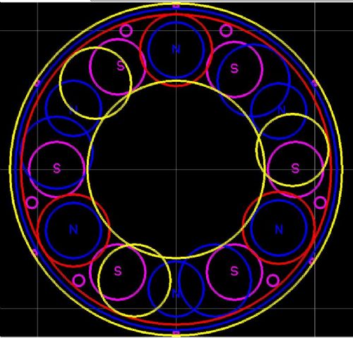
This is the proposed x-section view. very rough sizes, not to any scales. stub axle, supporting bearing housing with rotor attached. Stator connected to stub axle. 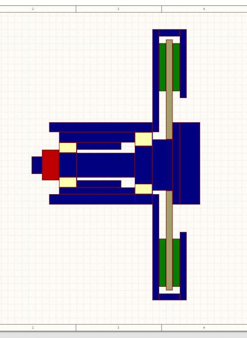
This is a photo of the coil testing rig. This is similar to the open style dual rotor AxFx alternator. The magnets are just temporarily fixed with a drop of cyano. This is with only 1 magnet ring at this stage. More magnets yet to arrive. A range of Fixed length spacers have been tested so far. I have tested an air gap of 10mm,14.5mm and 20.5mm. The 14.5mm is looking at being optimum so far. This will give approx 12mmx12mm coil sections, with a coil OD of 66mm and ID of 42mm. I still have some optimizing with the final coil and magnet positions. As large as possible final diameters to fit inside the perimeter ring. 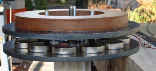
The final engineering drawings, machining and fitting will be done by Zest engineering. I don't have the necessary equipment to build the alternator. If all goes well, this design will provide high efficiency and robustness. It will be interesting to compare operating sounds from each windmill. Gordon. become more energy aware |
||||
oztules Guru Joined: 26/07/2007 Location: AustraliaPosts: 1686 |
I like the design, but hope the stator is "stubby" enough to remain stiff enough to resist harmonic vibration which may compromise the magnet faces under extreme load. It may be that you can use some creative coil design that will spread the outside coil wire into a thicker profile while taking the outer perimeter of the coils closer to the center of the coil(squash it inwards and fatter a bit). This would thicken the fibreglass outside the magnet path, and allow you to perhaps move the mags further out towards the perimeter radius a little bit more. This would in turn lower the leakage flux and and give a slightly higher magnet speed for the same rpm. If you did this for the inner leg of the coils, it would allow for thicker fiberglass at the fixing point end of the stator, and make for a stronger, less uniform stator... less chance of harmonics forming, while still keeping the magnet area of the stator at 12mm thick. This would probably require winding the coils in a winder where the two sides of the former were partly open, allowing the top and bottom of the coil wire to spread over the side whilst maintaining 12mm tolerance on the coil sides for the diam of the magnets. This of course would make the stator disk die more interesting.. 
Look forward to the updates ...........oztules Village idiot...or... just another hack out of his depth |
||||
| GWatPE Senior Member Joined: 01/09/2006 Location: AustraliaPosts: 2127 |
Hi oztules, the design is flexible enough to do all of the above. I intend to make a flat stator first. I have plenty of wire for testing. The relatively small number of coil turns makes it easier. Thickening in the centre is similar to my original design. This was much harder to mould. I may compromise and only thicken on one side. I have quite a bit of space to work with. I also intend to wind the coils from the inside out, to overcome the wire crossing over thickness and make a more uniform coil. These are mechanical aspects and not electrical, so won't affect magnet components too much. cheers, Gordon. become more energy aware |
||||
oztules Guru Joined: 26/07/2007 Location: AustraliaPosts: 1686 |
Gordon, here is a graph from Dinges.... something to ponder over a coffee perhaps. It plots the air-gap to testla. I found it interesting when trying to develop the best airgap/winding ratio. 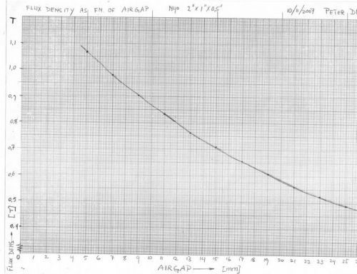
oztules Village idiot...or... just another hack out of his depth |
||||
| imsmooth Senior Member Joined: 07/02/2008 Location: United StatesPosts: 214 |
Gordon said "The new wooden blades have flown on the AxFx and F&P mills now. Not a great success on the F&P and overkill for the AxFx. The torque required to start the decogged F&P equates to about 15W of output power. This is how much power the AxFx mill produces, yet the F&P is yet to turn. They work well at higher wind speeds on the F&P, but the lack of starting torque will need to be adressed. " I don't know what your blades look like or if you solved this problem, but on my F&P before its destruction starting torque was never a problem. It easily started at about 4-5mph. My rotor was 10.5': blades were 5' 1" and offset 2" from the center on the hub plate. The key for me was getting a wide 10" root 2.5" deep. This gave the starting power along with the smooth, decogged rotor. My next set of blades for the Axflux will be 2.5" deep and 10.5" wide at the root. |
||||
| GWatPE Senior Member Joined: 01/09/2006 Location: AustraliaPosts: 2127 |
Hi imsmooth, I don't remember reading about your F&P destruction. Was this the unit with the specially made Neo magnets? My testing of 3m rotor on my F&P concluded that there was too much inductance limiting. My mill suffered with runaway in storms, even with the electric brake activated. This is why I cut them down to a 2.4m rotor dia. The wooden blades I have carved will work well on my new AxFx mill. The overkill, relates to starting in the lightest of winds. There is no power to harvest, <1W, but the mill is spinning. 10" of chord length will give a lot of torque. At least the AxFx mill will probably be able to keep it under control with the electrical brake, if you use the 2" round magnets. Gordon. become more energy aware |
||||
| imsmooth Senior Member Joined: 07/02/2008 Location: United StatesPosts: 214 |
The neo rotor worked great as did the brake until the winds knocked my tail into the brake cable, snapping it. The tail boom was too thin, and I did not size it properly for dynamic conditions. Once the brake was gone it was only a matter of time before the tail bowed into the blades, chopping them. The neo rotor cracked in the center from the impact, so now it does not sit correctly on the spline. It is a shame. The shunt controller was working well and the tower stood firm, and the furling was kicking in at about 25mph. The gusts, though, were knocking the tail around. So now I move on. This whole thing is more of a project and learning experience for me. I've learned how to weld, cut metal, carve blades, and use mosfets. I've even gotten to talk to some interesting people. With regard to the axial rotor, what do you do to ensure that the magnets don't fly off? I have seen fiberglass wrapped around the circumference and I have seen metal bands. Is fiberglass sufficient? |
||||
| GWatPE Senior Member Joined: 01/09/2006 Location: AustraliaPosts: 2127 |
Hi imsmooth, this explains what happened. You may be able to reuse the magnets on a new rotor. the magnets on my original AxFx mill [square magnets], are placed up against a machined step. The magnets were glued with cyano. I have since epoxy coated the magnets, when the nickel coating peeled off. My unit has much more magnet force between the rotors due to the very narrow air gap, but the magnets still stick to the iron brutally. My mill has reached 1200rpm without magnet failure. My new mill will have a milled step for each magnet as well. I had looked at carbon fibre, and this may still be an option for me in addition to the step. Centrifugal forces, and magnets slide, are the dominant areas to work with, with wider magnet rotor separation. I suggest you make a test unit, unless you follow another design precisely. Gordon. become more energy aware |
||||
| imsmooth Senior Member Joined: 07/02/2008 Location: United StatesPosts: 214 |
That has always been the plan. I will retro-fit my testing unit with Otherpower's stator bracket. I will be able to mount the magnetic rotor with a disc with the spline pattern cut in the center. I need to get up to 50v at around 100rpm. I would like to keep my maximum load voltage under 260v. This is because I have an arrestor set to go off somewhere after 250vac. |
||||
| GWatPE Senior Member Joined: 01/09/2006 Location: AustraliaPosts: 2127 |
I think that trying to mix and match may not be the best option. Just go for the full AxFx design. When I finish my new AxFx mill, the F&P will be kept as a spare. I did not attempt to reuse parts, even though the rotor cans are very similar. Gordon. become more energy aware |
||||
| imsmooth Senior Member Joined: 07/02/2008 Location: United StatesPosts: 214 |
You misunderstood. The testing unit is the pm motor and craddle I use to spin any rotor. I will be using the F&P shaft, but that is it. There won't be any generating component from the F&P. |
||||
| GWatPE Senior Member Joined: 01/09/2006 Location: AustraliaPosts: 2127 |
The testing of configurations for my new AxFx has almost finished. This unit is being designed for nom 48V. The final magnet airgap is 18mm. This leaves the coil thickness at 15mm, with 0.5mm glass cloth each side, and 1mm stator-magnet separation on each side. Each coil has ended up with 100 turns of 1.25mm wire. The coils will have in internal dia of 42mm and on outer dia of 72mm. This gives a coil 15mm x 15mm cross section of copper. The coils straddle the magnets with 4mm inside the magnet dia, and 11mm falling outside. This has allowed the coils to be flat and will make the stator easir to make. There is still some scope for the magnets to be positioned at a larger radius still. The mill will be configured with a voltage doubler, and the cutin will be close to 100rpm. This unit is being sized for connection to a 1.2kW grid tied inverter. It is expected that maximum power will be attained at an output voltage of approx 75-85VDC. The currents expected will be in the order of 15A at maximum power in my setup. I am expecting the efficiency will be above 90% across the useful output power range. The task is looking closer to completion. Gordon. become more energy aware |
||||
oztules Guru Joined: 26/07/2007 Location: AustraliaPosts: 1686 |
Tis getting nearer indeed. Do you have the foggiest idea of the load impedance range? I am guessing you feel about 5 ohms. Whats the phase resistance? (of a single coil group < 1 ohm I feel sure.... so looking at very good efficiencies) I assume that 100rpm is with the doubler in circuit. Should do very well with it. Sounds good ..........oztules Village idiot...or... just another hack out of his depth |
||||
| GWatPE Senior Member Joined: 01/09/2006 Location: AustraliaPosts: 2127 |
Hi oztules, probably close to it. I have just measured the coil resistance and it comes out to 0.25ohms. This is 4x the resistance I had calculated for 24V, which seems right. The 1phase resistance for this 48V system will be 0.75ohms. This is a little higher than I had originally calculated, but is still OK for a 48V system. The efficiency at maximum power [approx 80%] will not be as high as your mill, but will be more than adequate for my application. Efficiency at 50% load will be approx 90%. The larger dia of your rotors makes more efficient use of the magnets, but requires more copper. For RAW power, then dia will always rule. This exercise for me is to make a windmill to replace my F&P that can be successfully electrically braked in any wind conditions. This new machine has approx 9x the braking ability of the F&P, and will not suffer the problems with coil saturation, that allows my F&P mill to keep spinning in high winds when the outputs are shorted. I will be making a new dedicated controller for this mill. The mill will achieve cutin, approx 50VDC at 100rpm with the voltage doubler. At 400rpm, there is potentially 200VDC at the rectifiers if unloaded. The controller will be set to activate a heavy loading to the mill if the output voltage rises above 85V. This will be through a separate rectifier system. There is a period of time during the grid connection phase, where the mill could potentially be unloaded. When spinning at 150rpm, as in light wind conditions the mill will be braked softly. There will be little power. If the inverter suddenly lost grid connection at high power, then the mill would be braked hard, back to approx 150rpm, where the blades would probably become significally stalled. The rpm would be held close to this speed until grid connection was achieved again, where normal operation would resume. This should be achieved without PWM, but just ON/OFF with some hysterysis. Some decent mosfets with a 0.5ohm current limiting resistor [100-200W rating, probably just a bit more than the tower wiring] should suffice. I would expect that a hundred or more amps could be expected in the cct at full power. This will test the rectifiers as well. Diodes have good short duration overload performance. Stacked 35A rectifiers will be a cheap option. more info soon. Gordon. become more energy aware |
||||
| GWatPE Senior Member Joined: 01/09/2006 Location: AustraliaPosts: 2127 |
Hi readers, I have drawn up some CAD pics of expected shapes and assembly of my design. All parts bolt together. I am still working out the CAD program, so this is not exactly the final layout. Here are some of the pics of expected stages of assembly. This is the stub axle: 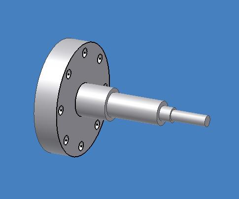
This is the bearing hub: 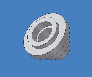
This is the front magnet plate/blade mount plate/joining ring: 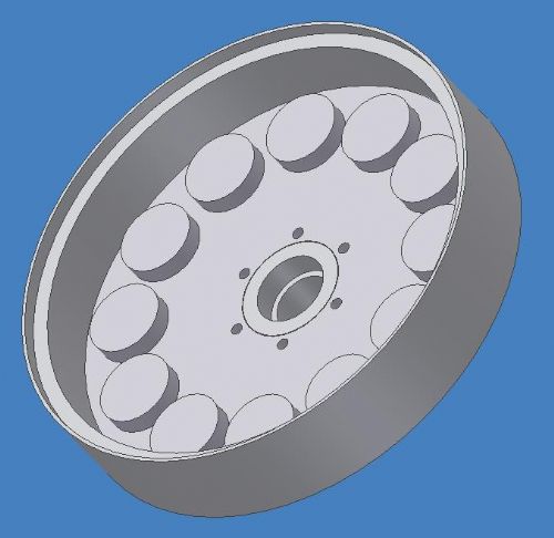
This is the front magnet assembly with the axle inserted: 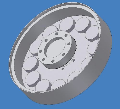
This is the rotor axle assembly with the stator attached: 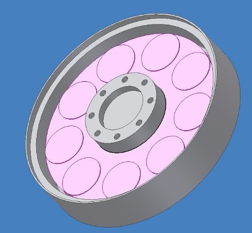
This is the final assembled alternator looking from the back: 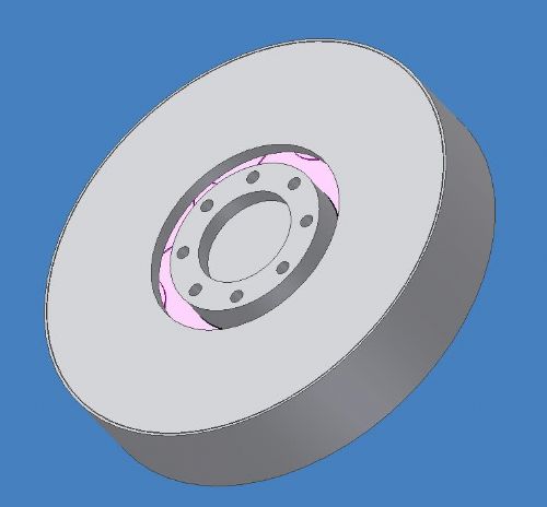
The assembly is designed so that the rotor is centred between the bearings, and all the torque from the blades is transferred directly to the magnet rotors. The stator is closely coupled to the yaw box with the short stub axle. The gap between the stator hub and the rotor is visible. The electrical wiring will exit the assembly through alignment holes in the coupling between the stator and the stub axle. The stator will be clamped between a metal ring and the axle flange mount and be aligned on a step on the flange, yet to be drawn on the pic. The design makes a compact unit that is sealed from blown sand and rain and the internals are well protected from direct sun, while allowing ventilation for cooling. I have not shown assembly bolt holes, or jacking bolt threads in the final back magnet plate, or bolt holes in the bearing hub. The machining is progressing as is the winding of stator coils. Gordon. become more energy aware |
||||
| Gizmo Admin Group Joined: 05/06/2004 Location: AustraliaPosts: 5078 |
Repost of missing post. This thread is almost a book! GWatPE wrote..... Hi imsmooth, I am intending that my new AxFx mill spins whenever my Davis cup anemometer spins. < 1kph. I have noticed that ball bearings seem to offer more drag if they are stopped for long periods. My new wooden blades that I carved are thin in section [low form drag] and have high aspect. A spinning windmill has more chance of harnessing the passing wind gusts than one that has to be started each time a small gust comes along and then stops again. The battery is spending more time at the float voltage. The small amount of power captured supplements the continuous small draw from the inverter laptop, and numerous controller systems connected. Here is a graph of the last year or so wind energy harvest at my place. Gordon. Hey Gordon I've lost that picture, could you repost it? Glenn The best time to plant a tree was twenty years ago, the second best time is right now. JAQ |
||||
| GWatPE Senior Member Joined: 01/09/2006 Location: AustraliaPosts: 2127 |
This is the graph that went AWOL. 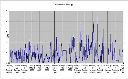
Gordon. become more energy aware |
||||
| GWatPE Senior Member Joined: 01/09/2006 Location: AustraliaPosts: 2127 |
An update on the progress of the dual rotor unit. The New AxFx alternator is progressing well. I have just finished casting the stator coils. I ended up only moulding on a sheet of glass. I was able to accurately place the coils on an epoxy soaked glass cloth that was wetted out on a sheet of waxed mylar that was placed on a sheet of glass. This resulted in an 0.2mm glass cloth layer on one side of the coils. When this had cured, I was able to make an electrical tape dam around and against the outside of the coils. I used a stiff glass fibre impregnated epoxy filler to fill the triangular holes formed between the coils. When this had cured, I was able to electrically connect the coils in a 3 coils in series 3phase star arrangement, and solder the joints and terminate with flexible tails. The inside was then cast with the same type of stiff epoxy glass fibre filler. The inside of the coils was not filled. This will allow full air cooling when I remove the glass cloth that still spans one side of the coils, so the coils will have a hole all the way through. The finished stator is very strong and sounds like a piece of glass when tapped. I will probably do some extended time, static current tests to see temperature rise and if softening occurs. So far I have made a complete stator without any machining. The individual coil mould edges were flat pieces of plywood. The hole former was hand sanded from scrap plywood to the hole size, slight oval/egg shape, 42mm wide and 48mm long, and then sanded to the correct 15mm thickness. The coils were wound by hand from cut lengths of enamelled magnet wire. I found it easier to measure the length first than count turns while having to apply glue, as the coils were cast on the former. The coils were reasonably evenly wound. I tried to avoid loose coils that created an uneven fill. The turns were not jam packed tight though. I am relying on the glass fibres to tightly hold the turns together. There is enough turn to turn contact to allow good heat conduction from the inside coil turns to the outside surfaces of the coil. The glass filler does reduce heat conduction between coils within the stator. The low coil resistance should minimise the heat generation within the stator. The stator will require machining to mate with the alignments on the stub axle. The stator has just under 2kg of copper in the coils. The magnet rotors and bearing hub and stub axle will be final machined to a fit around the stator. I will have a template made to accurately align the magnets. This has been quoted at under $20. Laser cutting of the aluminium template is the way to go. Next time, maybe even all the bolt holes in the steel magnet plates will be laser cut as well. The outside spacing ring that aligns the rotors is the only part that I would like to improve upon. Will need to think about this some more. Maybe some type of plastic pipe would be OK as well. There is surprisingly little force between the magnet plates at the 18mm spacing compared to say 3mm of my original alternator. The fitting of parts is the next step. Gordon. become more energy aware |
||||
| Gizmo Admin Group Joined: 05/06/2004 Location: AustraliaPosts: 5078 |
Good work Gordon, this should be a efficient machine when its finished. With the laser cutting of the aluminium template, see if you can get prices on waterjet cutting as another option. The standard CO2 metal cutting lasers find cutting aluminium very difficult, it needs full power and high pressure nitrogen to get a respectible cut. Aluminium, copper and brass are very reflective to the infra-red energy. A 2.5kw laser can cut 16mm mild or 10mm stainless steel easily, but 5mm aluminum is a real struggle. Waterjets, on the other hand, cut aluminum easier than steel, but are very very slow with stainless steel. Glenn The best time to plant a tree was twenty years ago, the second best time is right now. JAQ |
||||