
|

|
Forum Index : Electronics : 150V 45A MPPT - roll your own
| Author | Message | ||||
| poida Guru Joined: 02/02/2017 Location: AustraliaPosts: 1420 |
Here is the output of the Nano, as measured across the 5K pulldown resistor I have on Pin D9. This is light Blue trace. I have a 1K resistor in series with this output, which leads into the LED of the TLP-250. So the forward current is 5mA. Dark Blue is the output of TLP-250, when driven with a 12V supply, with bypass caps of 0.1uF ceramic and 10uF Tantalum, both located less than 3mm from the ground and 12V supply. 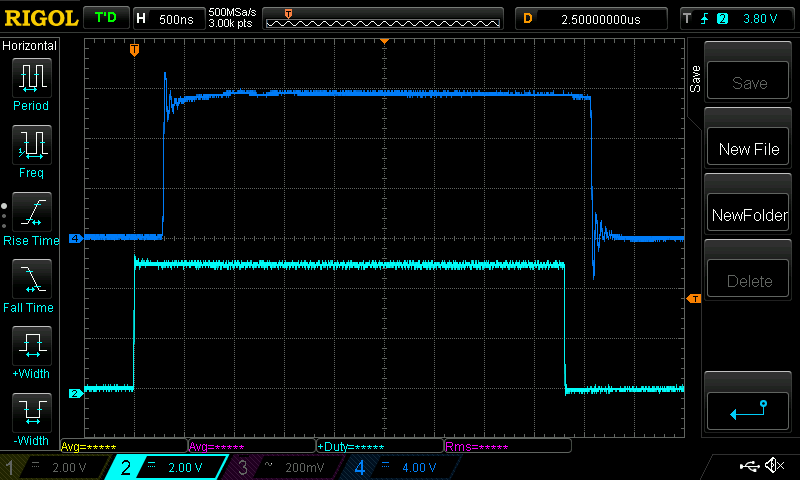 The TLV-250 specs say there will be a propagation delay of 0.15uS typical, and 0.5uS maximum delay. It appears we are seeing a delay of about 0.3uS for both turn on and turn off. No biggie. Here is the voltage at one of the two MOSFET's gate pins, after the signal passes through the 10 Ohm gate drive resistor. 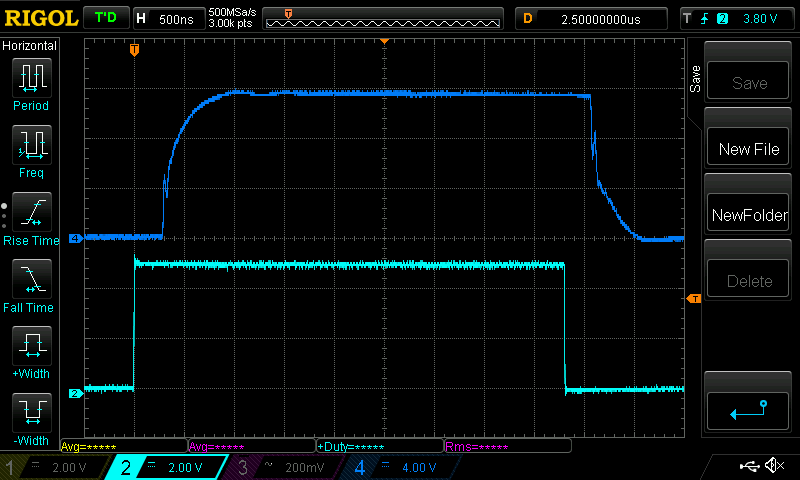 What a clear illustration of charging a capacitor. We could work out the capacitance of this maybe, if the current was constant. Which it probably is not. The MOSFETs are NOT driving any loads. The input voltage for the converter is zero. This is what we see when the MOSFETs are switching nothing at all. It's a capacitive load. I notice the ringing on the output of the TLP-250 and wonder if that can be reduced with some better bypassing cap choices. This will effect the quality of the MOSFET turn ON and OFF when switching proper loads. Something for the weekend I think. I can not accept that 5V from the Nano, via a 1K resisitor is insufficient to drive the TLP-250. The specs say best is to drive it with 8mA, I am driving it with 5mA. Notice the light Blue trace? 5V with a rise time of 4.6ns Here is the voltage on pin 2 of the TLP-250. Light Blue trace. This is the forward voltage of the LED inside the chip. The rise time is 25ns. The forward voltage is 1.5V and it gets there quickly and stays there. 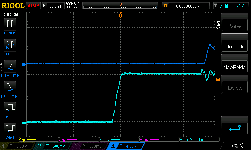 For sure, the Nano is not putting out the full 5V, I would estimate it to be 4.9V Close enough for government work. The worry that the Nano can not drive the TLP-250, using a 1K series resistor is to be discarded. The Nano drives it well and with no effort at all. wronger than a phone book full of wrong phone numbers |
||||
| poida Guru Joined: 02/02/2017 Location: AustraliaPosts: 1420 |
Mike, top and bottom. 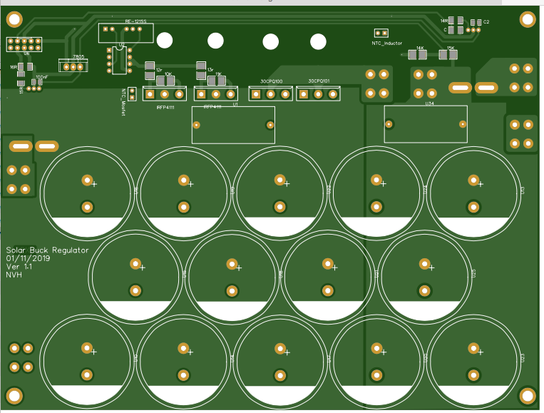 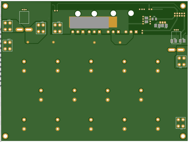 wronger than a phone book full of wrong phone numbers |
||||
| Solar Mike Guru Joined: 08/02/2015 Location: New ZealandPosts: 1138 |
Hey Poida, what are you using to prevent the battery bank discharging into the PV array at night when its outputting 0 volts. I would up the drive current somewhat from your 5ma; for as the opto's age they require more current to get same brightness, at some point in the future it may be an issue.. Cheers Mike |
||||
| nickskethisniks Guru Joined: 17/10/2017 Location: BelgiumPosts: 458 |
What is the mosfet you are using? Try switching your mosfet slower, it's possible you get a nice ramping up without shoot thrue arround the miller plateau. Try 20-30R, I've got nice curves with 25R and IRFP4110 on 15V, I switch off with 5R though. Pictures without load, (Ok, timebase is a bit wider with me) 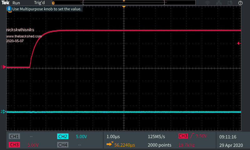 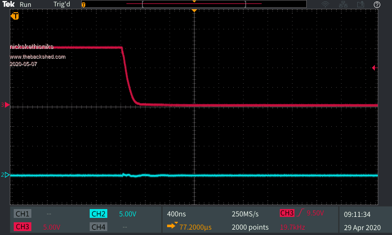 Edited 2020-05-07 22:46 by nickskethisniks |
||||
| nickskethisniks Guru Joined: 17/10/2017 Location: BelgiumPosts: 458 |
Peter did you consider the possibility the input capacitors have influence on your misbehaving code? It's possible your code thinks the solar panels are producing power, while in fact the electrolyrics are delivering most of the energy at some Point. Just a thought, not checked your code yet. |
||||
| wiseguy Guru Joined: 21/06/2018 Location: AustraliaPosts: 1156 |
Peter, the reason the manufacturers give recommended operating conditions and produce data sheets is so their parts can be used for best performance reliability and life. Their parts with the same part number they produce are all slightly different but they produce the data sheet and all those figures and graphs and guarantee that they comply with all the min typ and max values and graphs when they are run within their recommended operating conditions. This is not my interpretation it is fact. Whilst the opto parts you and Nick are using may be working with less drive current they are more susceptible to noise degradation, operating life and unknown performance for other specs such as temperature behaviour. It does not mean that the parts wont work when being used outside of their recommended parameters but that begs the question how close to poorer performance am I actually operating at. I saw this post that wanted to produce a reliable (Mark proof  ) MPPT product. ) MPPT product.Despite being built to a budget by home constructors who don't all have an in depth engineering knowledge, the recipe should meet or exceeds similar commercial products I saw what I believe to be a potential weakness in the design so I alerted to it. Would you prefer others and myself don't do this going forward ? I also see PCB layout issues that I believe are causing/contributing to the noise the nano is seeing. Sure you can add resistors and capacitors and software filters and galvanic isolators ad infinitum, or perhaps a few minor changes in the layout could also make life easier ? Edit: The schematic published here showed a LED resistor of 1K1, the data sheet has a max diode Vf spec for the part as 1.8V, the current to the LED would be 2.9mA if the Nano had a perfect 5V output. This is less than half the minimum spec recommended, 7mA (from your data sheet), that is what drove me to initially comment. Edited 2020-05-08 08:22 by wiseguy If at first you dont succeed, I suggest you avoid sky diving.... Cheers Mike |
||||
| poida Guru Joined: 02/02/2017 Location: AustraliaPosts: 1420 |
Mike, thanks for returning it with topspin for a win. Even though I read and re-read the TLP-250 specs I still did not see 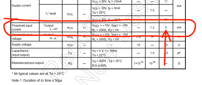 5mA possible threshold input current to turn on the LED! I am driving it 5mA by design via the 1K series resistor. So it's marginal already. You were right to persevere in trying to make me see the bleeding obvious. So the 1K resistor is OUT and the 620R is IN, to take the optocoupler input drive current to the recommended 8mA. Reading a few articles, Agago's Optocoupler Design guide and Broadcom's "Calculate Reliable LED Lifetime Performance in Optocouplers" white paper I see that the LED output does degrade over time. The rate of reduction in light output increases as the driving current increases. This degradation is of the order of 10% loss over 5 to 10 years for GaAlAS type LEDs so yes, there is some but to my mind there is not a lot. I did a quick test to see how marginal this particular TLP-250 IC is running. I put a pot in series with the Nano PWM output and the 1K current limit resistor. Glitchy switching appears with about 1,900 Ohms on the pot. Adding this to the 1K we get 5V / (1000 + 1900) = 1.7mA as the threshold for this board on the bench here at work. There are temperature effects on this no doubt. Please don't give up picking holes in my thinking. Clearly this is a service that needs doing. Maybe consider it a (non)combat sport and derive some fun from it? wronger than a phone book full of wrong phone numbers |
||||
| azhaque Senior Member Joined: 21/02/2017 Location: PakistanPosts: 117 |
Hi all, Poida I suggest that the tracks bringing the analogue voltage and current related information, should be broken just before these tracks join the connector pins. This break should be as close as possible to the connector and a ferrite bead be inserted there to choke the RFI crap before it enters the ribbon cable. This seems to be important because the tracks carrying the above info, particularly from the output side, traverse the whole length of the board and are thus more susceptible to picking up Rfi. Moreover out of the two (i/p and o/p) the o/p info seems to be more critical from a control loop perspective. Thus it needs to be as clean as possible. Regards azhaque |
||||
| poida Guru Joined: 02/02/2017 Location: AustraliaPosts: 1420 |
Good idea azhaque. Nicks? wronger than a phone book full of wrong phone numbers |
||||
| wiseguy Guru Joined: 21/06/2018 Location: AustraliaPosts: 1156 |
The MPPT product is what wins - I personally don't care too much about winning really, I probably care slightly more about having integrity. I have found too often in life often when you win you lose. Another way of looking at it is; some view coming second in a race is just the first loser to go past the winning post - but my view is all others that pass that post are technically winners too except for a slight matter of timing. With regard to the PCB, from inspection it appears that the 10 pin connector to the nano is maybe not on the best end of the board, leading to longish tracks carrying analog signals. Move the output neg connection to in line with the middle row of capacitors. Move the output positive down to where the neg terminal currently is. Introduce a clearance between the choke output screw connector and the + output forcing the choke noise to go to the capacitors & get filtered more first before feeding the current sensor. Return the lower divider resistor (solar vin) to the gnd of the 10 pin connector instead of the ground plane - electrically the same potential but we are trying to minimise noise. Return the mosfet thermistor to same point as above - not to the ground plane. It might be better if I sketch the rest of my suggestions & maybe Nicks and I could talk sometime as writing & explaining so much stuff takes a lot of time, and there will be questions. Please NB after my own designs are finished I always try to review them with new eyes and often find improvements. After you have been designing PCBs for many years your designs have greater chances of working first time with less issues because you avoid and do things by intuition & past experiences without even realising it. Please consider any suggestions I make as refinements and not as outright errors - this design is already 98% of the way already. Edited 2020-05-08 12:11 by wiseguy If at first you dont succeed, I suggest you avoid sky diving.... Cheers Mike |
||||
| azhaque Senior Member Joined: 21/02/2017 Location: PakistanPosts: 117 |
Couldn't agree more. A picture is better than 1000 words. See if you can do it in Easyeda. Regards azhaque |
||||
| poida Guru Joined: 02/02/2017 Location: AustraliaPosts: 1420 |
thanks Wiseguy. Onto another unanswered question: SolarMike asks (knowlingly) "what happens when the sky goes dark but the battery is still connected?" I see a current path from the battery+ through the inductor, through the body diodes of the two MOSFET switches and out to the solar array+ terminal. Both battery- and solar array- are connected via GND. There is nothing to stop battery discharge into the solar array at night. Some solutions include Schottky diodes in series on the solar array output. I saw another one that has a MOSFET but with the Source on solar array+ and it's Drain connected to the MOSFET switch's Drains. This is using the MOSFET body diode. The design also drove it's gate from the same drive output as the switch's drive to reduce losses from the body diode's voltage drop. I have no firm position on this. I am tending towards Schottky diodes on the input, combined with a capacitor pre-charge thing and a decent sized relay. The relay would be driven by the Nano to close the contacts once reasonable levels of power are being used. This is to reduce the diode Vf loss. I would program the relay to only switch about 1V at 10A, in that ball park, and so not suffer too much from switching DC. I might build this on a separate board, taking 12V for the relay from the brainboard. Or just combine it with the brainboard.. What sort of diode? 45A at 57V output is 2500W, this is the design maximum power. 100V in means 25A for the diode 65V in means 40A maybe one of these? a 600V, 60A continuous at 115 degC, in TO-247 for $5 Always easy to find a better choice,this one 150V, 80A with Vf of 0.9V and it has a negative tempco so it goes to 0.8V at 125C at 80A. $6.90 ea Vf is about 1.2V, max power dissipated would be 48W so it would need to be on the heatsink too. Reverse leakage current is about 0.5mA max at the highest temperature. wronger than a phone book full of wrong phone numbers |
||||
| Solar Mike Guru Joined: 08/02/2015 Location: New ZealandPosts: 1138 |
Poida, regarding the low pass noise filter for your A-D inputs, here is a circuit that I use a lot (10 Hz LP); uses a low noise rail to rail op amp. I make them on a tiny pcb 18 x 30mm fitted with a 4 pin pcb connector. Just place them on your CPU board close to the CPU inputs.Being an active filter it has a much sharper response than a simple RC combination. Here are the gerbers for a panel of them (9), using 1mm thick pcb, just cut out with tin snips. Gerbers_Filter_1003.zip Sorry all smd to get the size down. Cheers Mike Edited 2020-05-08 13:38 by Solar Mike |
||||
| shallowal Regular Member Joined: 26/07/2018 Location: AustraliaPosts: 58 |
Probably a really dumb Newbie suggestion, but what about back to back FET's. ie tie sources together and Gates together then drain of one connects to the panels and drain of the other connects to the battery.  Allan Allan |
||||
| poida Guru Joined: 02/02/2017 Location: AustraliaPosts: 1420 |
Shallowal: that would be a good thing to do if the PCB was to be redesigned. I want something separate from the main PCB, to permit different approaches. wronger than a phone book full of wrong phone numbers |
||||
| nickskethisniks Guru Joined: 17/10/2017 Location: BelgiumPosts: 458 |
Wiseguy I was hoping you would join the conversation, much appreciated! I will work on a list with things to be improved, don't know to which level we will get. About decoupling the solarpanels from the battery, I use UFB200FA 20P, I also have STTH12003 I bought from ebay for 5€/piece. They have about 0.85V drop at 30A (25°C) the hotter they get the more efficient they are. UFB200FA20 STTH12003 In my prototype controller there is no decoupling present, in my permanent setup they are! My Solar buck controller What I like about the SOT227 packages, you just bolt them to your heatsink or even case/housing and bolt your wires on them. There are 2 diodes in one package galvanic separated, and also galvanic isolation to the heatsink. With one package you can put 2 controllers in parallel. That's something great in theory but could fail in some situations, I think there was already some discussion about it. Don't think it's a problem when there are other protections incorporated in the "energy system". Edited 2020-05-08 16:17 by nickskethisniks |
||||
| wiseguy Guru Joined: 21/06/2018 Location: AustraliaPosts: 1156 |
Nicks did you use easyeda for this project? If not what did you use? can it be imported to Altium, can I have a copy of the schematic and pcb files to have a play ? You are welcome to pm me if you dont want to publish yet. If at first you dont succeed, I suggest you avoid sky diving.... Cheers Mike |
||||
| poida Guru Joined: 02/02/2017 Location: AustraliaPosts: 1420 |
Wiseguy and Nicks: I would like to put one request in here - please retain the 10 pin function mapping. This way I can continue to develop the code with the boards I have built already. I foresee a lot of changes are going to happen with the PCB. wronger than a phone book full of wrong phone numbers |
||||
| nickskethisniks Guru Joined: 17/10/2017 Location: BelgiumPosts: 458 |
Peter, don't worry from my side, I spent more than a day to solder and mount 3 power pcb's (first generation) in one housing. I'm not gonna swap them out. I will use those boards, but I'm happy to work on an improved version, but it must stay compatible with the first one like you and I are using. I will put version 1 online, if you agree I put version 2 online as well. And make a list to work on version 3. I need to check if I can concert to altium format. Everything is drawed in easyeda. |
||||
| wiseguy Guru Joined: 21/06/2018 Location: AustraliaPosts: 1156 |
Nicks send me the easyeda files and I'll have a go at using it.....cant wait..... If at first you dont succeed, I suggest you avoid sky diving.... Cheers Mike |
||||