|

|
Forum Index : Electronics : 6Kw Ozinverter build
| Author | Message | ||||
renewableMark Guru Joined: 09/12/2017 Location: AustraliaPosts: 1678 |
Oz said to give it a go doing 4 and see how it fits, so I'll give it a crack. Cheers Caveman Mark Off grid eastern Melb |
||||
oztules Guru Joined: 26/07/2007 Location: AustraliaPosts: 1686 |
I use the 2mm wire from the inspires for the secondary, and the primary too sometimes... this equates to about .32r secondary, your at .5R So try to get the fourth one in there if you can keep it tidy. If you need to overlap some, insulate them from the bottom layer with the mylar. You don't want any enamel touching enamel if you can avoid it. It is ok between each turn, as the potential between wires is less than 2v, but as the ends near, that climbs to 230v... if you can understand that logic  With 1.6m, you should have enough room to do the primary nicely... hopefully. .........oztules Village idiot...or... just another hack out of his depth |
||||
renewableMark Guru Joined: 09/12/2017 Location: AustraliaPosts: 1678 |
Mad, I didn't take pics of the voltage/light test I did yesterday. I'll do the same test on this third winding tomorrow, I'll put pics up then. Oz I actually did get that, brain is working nicely as I haven't been exposed to kids or women for a number of hours. Cheers Caveman Mark Off grid eastern Melb |
||||
Madness Guru Joined: 08/10/2011 Location: AustraliaPosts: 2498 |
You still have gaps between the wires so the next layer should fit in nicely. Are you sick of looking in that hole yet? It is like inverter porn. There are only 10 types of people in the world: those who understand binary, and those who don't. |
||||
| Warpspeed Guru Joined: 09/08/2007 Location: AustraliaPosts: 4406 |
If anyone wishes to measure a low resistance like this fairly accurately, feed exactly 1 amp of dc through the winding. Then measure the voltage across the winding. If the winding is exactly 0.490 ohms it should produce 490mV. Cheers, Tony. |
||||
renewableMark Guru Joined: 09/12/2017 Location: AustraliaPosts: 1678 |
You're an unusual man mate Cheers Caveman Mark Off grid eastern Melb |
||||
oztules Guru Joined: 26/07/2007 Location: AustraliaPosts: 1686 |
"You're an unusual man mate " When you finish this one and vow to never do this transformer stuff ever again, I won't be surprised to see you on here doing the second one..... just a bit better... and just in case or whatever.... it becomes a sickness. .......oztules Village idiot...or... just another hack out of his depth |
||||
renewableMark Guru Joined: 09/12/2017 Location: AustraliaPosts: 1678 |
Ahahahhahah, I have actually really enjoyed making this, it hasn't been the hell some make it out to be, I did get sore hands one time, but that was when I was trying to straighten the wire between my thumb and fingers as I wound it on the spool. Then I came up with that machine, but the fellas told me I was working the copper too hard (F Ya) I was quite proud of my machine. Anyway so far I have really had fun making it, getting back into fitting components on a board brought back memories, I had to think how long it has been since I did a jaycar kit, it was prob 25 years ago. Bloody hell time flies. Cheers Caveman Mark Off grid eastern Melb |
||||
| Warpspeed Guru Joined: 09/08/2007 Location: AustraliaPosts: 4406 |
Mark, 1.6mm wire is far more flexible and much easier to work with. If you want to be a superhero and get to wear your underpants on the outside, try winding one with 2.0mm wire. Its real character building stuff.... I guess each of us use what we have on hand, or can most easily get. No real surprises there. If you are a masochist stuck with the 2mm wire, then probably about 114 turns are all that you are going to be able to fit onto one full layer, allowing for the fact that as the hole gets smaller, each layer has less room. The skinny wire offers the advantage of being much easier to wind and opens up the possibility of fitting in more turns per layer. To compensate for the thinner wire, an extra layer is going to be required to keep the final resistance about the same. If given a choice, the 1.6mm wire with more turns and an extra layer will be the better solution, and much easier to fabricate. Cheers, Tony. |
||||
renewableMark Guru Joined: 09/12/2017 Location: AustraliaPosts: 1678 |
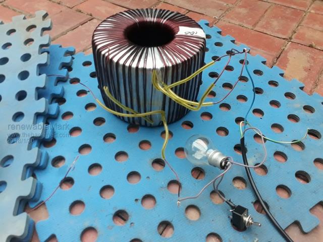
 Here is the test rig I made up from Oz's instructions. Madness had a great suggestion to leave an extra metre of copper on the end, just in case the counts were wrong and you would easily wind on another turn. The test is to connect the start ends together and place a nuetral wire on that. I cut up an old power lead from something, on the active line I soldered on an old style filament globe as a soft start, the switch is to short out the globe, effectively eliminating it from the circuit. Basically as per reply 3 on here After I did the test and it all worked out well, just to be sure I wound on another turn,(with that extra metre of wire) and as expected the voltage rose around 2v, so that double confirmed my turn count was correct. I have three windings on now and one more to do. I thought I only had to do three windings and got a bit sloppy with the spacing on the last wind, so there ended up having a gap of about 1.5cm between the start and finish ends, shouldn't matter too much. Cheers Caveman Mark Off grid eastern Melb |
||||
renewableMark Guru Joined: 09/12/2017 Location: AustraliaPosts: 1678 |
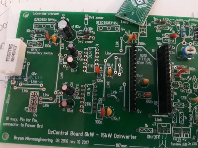
Started to put some bits on the board, haven't soldered anything yet. Where it shows a link, what gauge wire should I use there?  Cheers Caveman Mark Off grid eastern Melb |
||||
| Warpspeed Guru Joined: 09/08/2007 Location: AustraliaPosts: 4406 |
I think I know what is up with Mad. There's a full moon. Cheers, Tony. |
||||
renewableMark Guru Joined: 09/12/2017 Location: AustraliaPosts: 1678 |
WTF, you're the one talking about wanting to wear undies on the outside. Please don't tell me you have a borat mankini. Cheers Caveman Mark Off grid eastern Melb |
||||
| Warpspeed Guru Joined: 09/08/2007 Location: AustraliaPosts: 4406 |
I have no idea what a borat mankini is, had to look it up. But the joke about superheroes all wearing their underpants on the outsie is very old (like me). They ALL do it, superman, Batman, Spiderman and all the rest.  Cheers, Tony. |
||||
renewableMark Guru Joined: 09/12/2017 Location: AustraliaPosts: 1678 |
OK so just a small wire for the links yeah? Cheers Caveman Mark Off grid eastern Melb |
||||
| Warpspeed Guru Joined: 09/08/2007 Location: AustraliaPosts: 4406 |
Yes, just a small piece of tinned copper wire looks pretty neat. Cheers, Tony. |
||||
| Tinker Guru Joined: 07/11/2007 Location: AustraliaPosts: 1904 |
Don't worry about that gap, mine has a much bigger gap and it still works well. You certainly do *not* want the beginning and end turn touching unless you slide extra insulation over it if it can't be helped. You won't regret doing 4 in hand, mine was wound 4 x 1.8mm wire and runs very cool despite having only 100 turns - I wish I had done more - back then the importance of that was not being discussed so well so you benefit now. Don't be stingy with your primary wire either. You should use 9x4 of the same wires as the secondary, twisted together, if you use recycled wire. In case you are wondering; turns ratio = 9:1, total wire cross section is also. Klaus |
||||
| Tinker Guru Joined: 07/11/2007 Location: AustraliaPosts: 1904 |
Or, if you want to be really fancy, you can buy zero ohm resistors for that purpose. Klaus |
||||
| Warpspeed Guru Joined: 09/08/2007 Location: AustraliaPosts: 4406 |
Klaus it quite right, your secondary will be four 2mm squared wires = 8mm squared total secondary copper area. The ratio will end up somewhere around 9:1 so the primary ideally should be 72 mm squared total copper area, or close to it if that can be done. Quite a few different ways to approach that, depending on how much of the hole you have remaining, and what you have available to use. Its going to be pretty big, around 14 or 15 turns of 10mm diameter bare copper, if its going to be a single round wire. And any insulation around the wire will add to that diameter. Cheers, Tony. |
||||
Madness Guru Joined: 08/10/2011 Location: AustraliaPosts: 2498 |
Mark I think you will find the links marked on that PCB are actually already connected if Clockman has had them made as double-sided. Put your meter on it and check for connectivity. I have to agree with Tinker it is worth putting the extra wire on particularly if you plan to make the Inverter earn it's keep. What do you plan to use for the Primary? 70 mm square fitted for me with gaps but I have 11 turns, you will need 14 turns if I am correct. When you get the 4th wire on wrap 14 turns of any old insulated wire and check the voltage, you need to 26-27volts. Add or subtract turns till you get that result. You can then do some measuring and see how thick you can make the primary. Welding wire with the outer layer stripped off is very supple and will squeeze quite a bit. Although I would use recycled copper that you stripped off if possible, but you might like to spend another $100 plus on the welding wire. When you start winding the primary you need to get the wire hugging the inside of the core, if it sits out a bit it fills up the circumference of the hole very quickly. I found tyre levers very useful to get things into shape at that stage. Warp you should live a little and try having a good howl at the moon. There are only 10 types of people in the world: those who understand binary, and those who don't. |
||||