|

|
Forum Index : Solar : Grid connected inverter off grid
| Author | Message | ||||
Madness Guru Joined: 08/10/2011 Location: AustraliaPosts: 2498 |
It lasted 20 years, 5 of those with me. The only thing it would not run was an abrasive metal saw and it did not like going backwards with a GTI ramming electrons down its throat. Yes I am sure there were brown stains when it went off, it was like those crackers that are all tied together. There are only 10 types of people in the world: those who understand binary, and those who don't. |
||||
Revlac Guru Joined: 31/12/2016 Location: AustraliaPosts: 1024 |
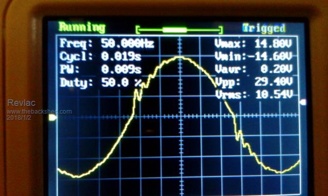
20 years old, not to bad at that age. Imagine the KWH's its done, not full time but still. Thought I would try the old selectronic inverter that is in the OLD FARTS motor home (haven't heard from him for months), Expecting a good sine wave.  I see some spikes above 0 crossing on the leading edge (expanded for a better view) I think that is where the white smoke and fire crackers are trying to get out, so better I turn it off. He might be up for a new inverter and some new underwear (if) when he uses it next.  Would not have Known about it without the CRO. Cheers Aaron Cheers Aaron Off The Grid |
||||
Madness Guru Joined: 08/10/2011 Location: AustraliaPosts: 2498 |
I have seen waveforms like that, could be something to do with the inductor if it has one. There are only 10 types of people in the world: those who understand binary, and those who don't. |
||||
| Warpspeed Guru Joined: 09/08/2007 Location: AustraliaPosts: 4406 |
It can also have to do with the nature of any load, or when running under no load at all. To give it a fighting chance, try monitoring the waveform with just a light resistive load such as a single light bulb. A perfect low distortion sinewave is simply not necessary, try looking at the grid voltage its pretty awful but everything runs fine on that. Anyhow, for thirty bux, these small oscilloscopes are excellent value. Cheers, Tony. |
||||
Revlac Guru Joined: 31/12/2016 Location: AustraliaPosts: 1024 |
Just tried the little selectronic inverter again (curiosity got to me) the spikes above 0 crossing do shrink a bit when applying a load up to 85w on the output, probably need 150w to remove the rest of it, If it went the other way I think that would be trouble. The inductor sat on top off the toroid. Anyway I wont touch that inverter again, found a cell in 1 of his batteries has dropped its guts. I don't have grid power available here anymore (got rid of it pole and all) so no way to test the wave form on the grid. It would be looking pretty rough I'm sure, used to hear strange sounds in transformers, motors, light ballasts, radio's and nasty voltage spikes and over/under voltage 275vac to 160vac NOT GOOD. Probably why a lot of GTI's eventually give up. So I think a grid tie inverter running off grid would have a much better life because offgrid power is much better regulated and cleaner. Cheers Aaron Cheers Aaron Off The Grid |
||||
Madness Guru Joined: 08/10/2011 Location: AustraliaPosts: 2498 |
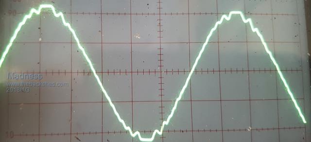
My Inverter goes very quite when the GTI is in operation, more so with HF ABB or Zeversolar, the Aero-sharps do the same but to a lesser extent. Here is the wave form of the now dead Trace, need to get someone to help me get all 78 KG of it off the wall. It buzzed away when running but never had any issue powering anything off of it. Maybe I should try building one of Warps boards for it.  Last time I looked at the grid it was much smoother than that. As you found out the grid is a very good lightning transmitter. There are only 10 types of people in the world: those who understand binary, and those who don't. |
||||
| Warpspeed Guru Joined: 09/08/2007 Location: AustraliaPosts: 4406 |
I have just purchased a document camera with a macro lens from e-bay. That is supposed to be able to focus right down to 50mm distance, so I should soon be able to post nice (in focus) pictures of small objects such as electronic components, circuit boards and oscilloscope screens. Cheers, Tony. |
||||
Madness Guru Joined: 08/10/2011 Location: AustraliaPosts: 2498 |
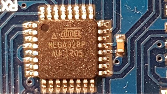
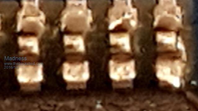
Photo of CRO above is taken by my phone, using a magnifier app on my phone also able to pictures as per below.   The black part of that chip is 6.5mm across, the second photo is of its legs. There are only 10 types of people in the world: those who understand binary, and those who don't. |
||||
| hotwater Senior Member Joined: 29/08/2017 Location: United StatesPosts: 120 |
I can't read a chip anymore without a USB scope. |
||||
| Warpspeed Guru Joined: 09/08/2007 Location: AustraliaPosts: 4406 |
My hearing is now so bad, I can no longer use the telephone, and most general purpose (low cost) cameras seem to be pretty poor for real close up high resolution macro photography. The lowest cost way to go about this seems to be with a "document camera" purpose designed to photograph postage stamp sized objects, up to about A3 sized objects. Many possible ways to do that, but most start to get expensive. The simplest and most convenient is a small document camera that comes mounted on a convenient multi way swivel arm, that can auto focus right down onto a bees bum. Cheers, Tony. |
||||
Madness Guru Joined: 08/10/2011 Location: AustraliaPosts: 2498 |
I use the magnifier app regularly, if you already have a phone with a decent camera it is free. I can't read the print on the chip above without it, even with a 2X magnifying glass/lamp. Another app I find very useful also is electro droid, has things like ohms law, voltage divider calculator and a whole lot of other resources and it is always there when I need it. There are only 10 types of people in the world: those who understand binary, and those who don't. |
||||
| George65 Guru Joined: 18/09/2017 Location: AustraliaPosts: 308 |
Tony, I was recently at the dentist and he showed me a little dental camera he has. The thing does many time life size magnifications even on a small screen. It may allow you to poke it into gear for a look round without disassembly as well as take pics of chips and components on boards etc. The dentise said he had been paying over $1000 for the " good ones" but they were nothing but headaches and unreliable. His dentist mate said he was mad to spend so much and buy the cheapies. He said he bought 5 over a year ago and hasn't got past the first 2 as yet, one in each surgery. The res on the things seems good and they are easy to use with the software that comes with them. I have been looking for a reason to buy one myself as they seem so nifty but now only having 6 teeth left and not having the thought one would be handy, I'm reluctant to buy any more camera's to sit around doing nothing. They seem cheaper than the document camera's at under $25 so Hopefully they might be something you could use and benifit from. Dental camera |
||||
renewableMark Guru Joined: 09/12/2017 Location: AustraliaPosts: 1678 |
I got some of those chips for the Ozinverter arrive, Jeeeezus they are small, they won't be fun to solder. Cheers Caveman Mark Off grid eastern Melb |
||||
Madness Guru Joined: 08/10/2011 Location: AustraliaPosts: 2498 |
The trick to solder them is to use SMD flux, you need to do it under a magnifying glass. Put flux on the PCB pads and get the chip in place and push it down into the flux. Then with a fine pointed iron and virtually no solder on it touch one of the pads, solder should flow from the tip across to the chip connection. Make sure it is exactly in the right place, if not correct it, once it is right repeat the same on the opposite side so that it can't move. Once you have the first 2 on do the rest but always keep as little solder on the iron as possible otherwise it will short out terminals. Have some solder wick on hand to clean up excess solder if needed. When done check every connection for continuity and shorts. Don't put solder on the job just the tiniest amount on the iron, the flux will do the rest for you. There are only 10 types of people in the world: those who understand binary, and those who don't. |
||||
| Warpspeed Guru Joined: 09/08/2007 Location: AustraliaPosts: 4406 |
George, wow that dental camera is really interesting. The USB2 one I have ordered (for around $100) comes fitted to a long adjustable arm, 2 mega pixels, fairly generous zoom range, and auto focus. I can use this hands free to look at things, which is probably better than something small on the end of a loose cord. Should also be good as a surface mount soldering aid instead of the microscope that is also on my wish list. Cheers, Tony. |
||||
| Mulver Senior Member Joined: 27/02/2017 Location: AustraliaPosts: 160 |
Do you have a recommended SMD Flux? |
||||
Madness Guru Joined: 08/10/2011 Location: AustraliaPosts: 2498 |
This is what I use. There are only 10 types of people in the world: those who understand binary, and those who don't. |
||||
| Mulver Senior Member Joined: 27/02/2017 Location: AustraliaPosts: 160 |
Cheers, Added to my basket!  |
||||
renewableMark Guru Joined: 09/12/2017 Location: AustraliaPosts: 1678 |
Dang wee hell, I'm going to need a better soldering iron. Does this one look ok? here Just having a look at jaycar and found this That looks nice, I'll put my bets on, ripper!! Cheers Caveman Mark Off grid eastern Melb |
||||
| Tinker Guru Joined: 07/11/2007 Location: AustraliaPosts: 1904 |
That soldering station is very nice but, IMO, a bit over the top if you are just building one inverter. I use just a simple temperature controlled solder station from Altronics (Jaycar stuff is too expensive for me and Altronics gives me trade prices). The trick here is to get a very fine tip, 1mm or close to that. The solder paste madness posted a link above is much cheaper as the stuff I got from Altronics - wish I had known & checked Ebay first. A trick, beside the good ones mad mentioned, for soldering 32 pin SMD chips is to clamp it in place before clumsy or shaky hands poke a fine soldering tip at the tiny pins. How to clamp? if you have a narrow cloths peg or something like it it might do. I use a little spring loaded heat sink device which is designed to clamp around small transistor legs to suck up heat during soldering. Its fully made from aluminium and has a quite gentle force to hold the chip in place. Perhaps they are now on ebay, I had mine for donkeys years. Another trick, I use a small swivel vise (clamp to desk job) to hold the small carrier PCB for soldering. I can then locate the job conveniently under my illuminated magnifying light. Do triple check the #1 pin dot lines up with the PCB mark! Beware also, there are two types of that carrier around, my first one I got sent from madness and it had the pin rows wider spaced than the ones I received later from ebay. I think oztules board uses the wider spaced carrier, I laid out my own board to accept either. Another trick, when soldering the inline pin strips, its easy to get them leaning sideways if you solder them individually, making it hard to plug the board in later. I always solder the inline pins & connector strips while they are plugged together and inserted in their respective PCB's, this ensures they line up perfectly. The SMD gets soldered after that, just unplug the carrier and clamp it in the little vise. Klaus |
||||