
|

|
Forum Index : Electronics : OzInverter OzCntrl PCB rev12 Sept2017
| Author | Message | ||||
Madness Guru Joined: 08/10/2011 Location: AustraliaPosts: 2498 |
Yes I am gun shy and will not under any circumstances be shorting out the 120r again. If I need to reset I will do as I did successfully before and drain the caps and do a cold start. Somehow things work for you that I can't replicate. As for breakers here is what can happen with the wrong type of breaker on DC. There are only 10 types of people in the world: those who understand binary, and those who don't. |
||||
oztules Guru Joined: 26/07/2007 Location: AustraliaPosts: 1686 |
No, thats not useful at our voltage levels. That can't happen at 48v, the aperture is too big and fast, you need much higher voltages to sustain an arc than we have use for. The only down fall I can see is welding the contacts on a make situation, and thats only because of hundreds of amps for an instant... spot welding current. Most makes I have tried don't cause any problem with it, which is surprising really, but some cheapies did... some did not. I spent a fair bit of my life working on 48v traction machinery, and 48v high current contacts are not what you would think. gapping is always less than 12mm, normal in the big ones around 10mm...yet can run switch 60v@300 amps all day long... and they do ( think fork lifts before the later pwm systems. The gapping on these din o/loaders is much much greater, so I don't loose sleep on the breaking arcs...... but the making splat is much more interesting, and I am surprised they can handle it as well as they do ( most of them ). For roof solar, that demonstration is too timid, it is much more dangerous than that up in the 450vdc ranges, but for 48v systems is not relevant in my eyes. "Somehow things work for you that I can't replicate."..... it's a Queensland thing perhaps... this is Tassie.... and I'm a mutant.... so special powers  .........oztules Village idiot...or... just another hack out of his depth |
||||
| Warpspeed Guru Joined: 09/08/2007 Location: AustraliaPosts: 4406 |
Its all relative I suppose. I was using standard 10 amp wall switches to switch 240v dc into a bunch of 75 watt light bulbs used as a test load for a high power dc/dc converter. The result was pretty scary. Switching on was fine, but switching off, the lamp sometimes remained lit for several seconds, with some audible "fizzing" and hot smells from the switches. Using standard AC circuit breakers up to 48v should be fine, as they are made to break very fast and have a very wide open contact separation. But also be mindful that any series inductance in the circuit may continue to arc over a considerable distance. Once a plasma arc has formed it takes very little voltage across the arc to keep it going. Most arc welders, MIG, TIG and stick work at voltages around 48v and lower. So if an arc does start, it just might keep going fairly easily at that voltage. If you have done a bit of welding, it can be surprising how far you can draw out an arc once it forms. Standard circuit breakers at 48v dc will probably be o/k unless the circumstances are rather unusual. Many people do this and it appears to work fine. And you cannot argue with success. Cheers, Tony. |
||||
Madness Guru Joined: 08/10/2011 Location: AustraliaPosts: 2498 |
Been thinking about this reset failure business. Oz what would you suggest is the best way to get the control board into the overload state without actually having an overload. The reason I ask is I want to test it with bare minimum FETs, no caps etc. Would introducing 5 Volts into the current sensor diodes be enough to trigger it? I have thought about it and I need to work out why it failed and eliminate that possibility. Never say never etc... There are only 10 types of people in the world: those who understand binary, and those who don't. |
||||
| Mulver Senior Member Joined: 27/02/2017 Location: AustraliaPosts: 160 |
Madness, I have been trying my best to keep up to date with your recent events... Do you believe that when your GTI failed your inverter went into overload and it failed to shut down correctly? |
||||
oztules Guru Joined: 26/07/2007 Location: AustraliaPosts: 1686 |
Well done Mad... first thing to do is get back up on the horse. Yes just get the scr to trigger, and you have fault condition. When it conducts, it forces the 8010 into current panic, and shuts off the driver chips directly.... There are three ways to do this. You just need to make the gate positive with respect to the cathode...... OR put excessive volts across the anode cathode past the breakover voltage.... OR.... and this is the one I like... .......be brave, show it who's boss.......rustle up some moxy, and jam a screw driver in the scr from gate to anode....  Consider that the 2110 has undervoltage lock out, as does the 8010, and you can see why I can't see how it failed from shutting down the 48v. No matter how I look at it. To compound the disbelief, you had the on off switch... off... so no matter what we did with the 8010 inputs, it had the spwm shut down physically from the on/off switch... thats why I think you have bigger fish to fry there. Until you can reset safely like I do, there is some hidden problem in there somewhere, waiting to get you when your not looking. It needs individual gate source resistors, so noise can't false trigger, which I suspect may have happened, can't see what else could. When the 120r is short to ground, there is no power in the control card anywhere... but full potential is still across the fets... so the only trigger can be from the driver network you have, and any noise that may get in the gates from where ever. That may mean the damping needs to be rock solid in the TIP 41/42 drivers on the main board also.... The first step for me is a gate source resistor on every fet, and at the totems at driver inputs. They need to be off if no signal is available...... Run out of ideas for the moment .........oztules Village idiot...or... just another hack out of his depth |
||||
Madness Guru Joined: 08/10/2011 Location: AustraliaPosts: 2498 |
The control board I was using when the crap the fan was the previous generation without the SCR to shut it down instantly on overload. From what Oztules has said he believes the shorted IGBT's in the GTI put the 350 odd volts DC from the solar panels into my home grid and the inverter causing the Inverter to have a fatal hernia. Which I am told could not be prevented with any version of the control board. I was not aware of this issue and replaced the electronics in the Inverter with my power pcb and the latest Oztules control board. It also made a very loud bang when the GTI connected. The man who is much smarter than me from Tasmania with 2 brains said if I was using a Aero-sharp GTI it would not have happened. This because the DC from the panels is isolated by the transformer. There are only 10 types of people in the world: those who understand binary, and those who don't. |
||||
Madness Guru Joined: 08/10/2011 Location: AustraliaPosts: 2498 |
I would have thought you being a farmer now you would use fencing wire to fix it. There are only 10 types of people in the world: those who understand binary, and those who don't. |
||||
| brac321 Regular Member Joined: 30/11/2016 Location: SloveniaPosts: 54 |
Mad for over current tests w/o load I use two old/exhausted AA batteries, connected where the CT should be, total voltage cca 2,4v. OffGrid 24/7: 250w black mono solar panels 6.4kWp, 1x Midnite Classic 150, 1x MorningStar MPPT 60, battery bank 840 Ah @ 48v, modified LF-8K inverter, DC/DC, hot water harvesting, etc. |
||||
| Clockmanfr Guru Joined: 23/10/2015 Location: FrancePosts: 429 |
Oztules, Mad, Along time ago when we started playing with the 8010 chip, Oztules got some 8010 chips with a different number on them, and found that several things were not on the 8010 chip that should be. So I am wandering about that?. In my book, supplement, I am persistent that you should get the 8010 chip with HN1518HT1536 on it. I recall 'Frackers' mentioning that there was some spare k for coding on it. Regards AC breakers for DC use. 10 years ago I had a chat with a guy from the tech department of HAGER MCB/breaker section. He reckons that DIN rail mounted Hager AC NBN breakers will work with DC up to 60vdc, and you must allow about a 8% de-rating of a AC for DC use. On all my other DC stuff, wind turbines, etc, Hager NBN types is what I use over the past 10 years. But over 60vdc I revert to DIN rail mounted Midnite Mini Breakers that are designed for a high DC voltage. Everything is possible, just give me time. 3 HughP's 3.7m Wind T's (14 years). 5kW PV on 3 Trackers, (10 yrs). 21kW PV AC coupled SH GTI's. OzInverter created Grid. 1300ah 48v. |
||||
| Clockmanfr Guru Joined: 23/10/2015 Location: FrancePosts: 429 |
The Latest OzControl Board 12b, Oct 2017. Still some LINK and writing to add for the DIY PCB makers. Double sided board with Everything on one side, and LINK tracks on the other, so the DIY folk can add links under or on top. I have beefed up some tracks for anti-substrate separation when soldering/desoldering components. Nothing worse than desoldering and the blasted PCB solder Pad comes away. Also allowed more space around board components for different size bits that folk can find. Although I have not tested this latest board, I will put the Gerber Files on later. 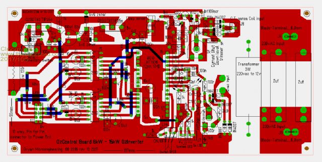 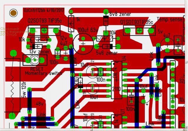 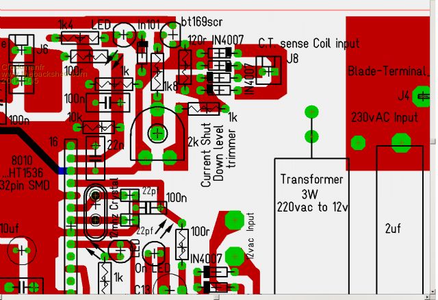 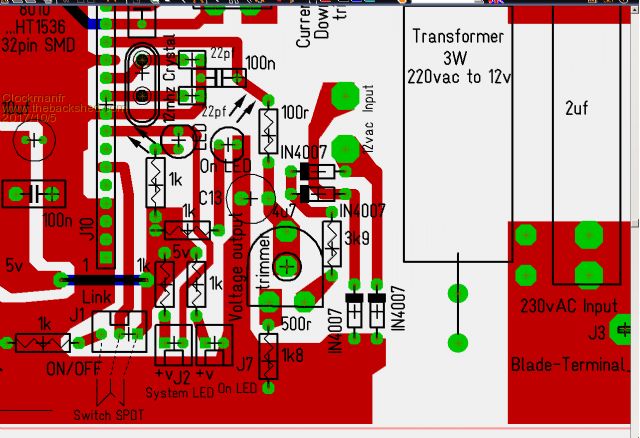 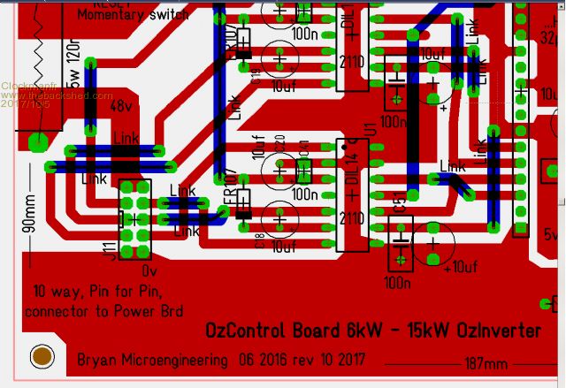 Everything is possible, just give me time. 3 HughP's 3.7m Wind T's (14 years). 5kW PV on 3 Trackers, (10 yrs). 21kW PV AC coupled SH GTI's. OzInverter created Grid. 1300ah 48v. |
||||
| brac321 Regular Member Joined: 30/11/2016 Location: SloveniaPosts: 54 |
Clockman one suggestion if I may? Draw 230v part of copper more sideways from carrier holes - safer distance... I would minimize these routes, there is no need to be there to the end of PCB and all around. Same for plus pole, supply line from 120E resistor shall be wide enough, but not spilled all around if you don't want to spread unwanted noises from power board. Very important is ground plane, you have done it good  Sometimes is (when using CPUs, ASCIs, etc) at PCB designing process most important to draw Faradays cage of ground plane all around the board. Doing this will limit internal "noises" to spread at large out and also prevent - limit outside disturbances to take influence on your circuity, like here or here on some of my boards. OffGrid 24/7: 250w black mono solar panels 6.4kWp, 1x Midnite Classic 150, 1x MorningStar MPPT 60, battery bank 840 Ah @ 48v, modified LF-8K inverter, DC/DC, hot water harvesting, etc. |
||||
oztules Guru Joined: 26/07/2007 Location: AustraliaPosts: 1686 |
Clock, thanks for the clarification re breakers. Yes the first 8010 chips I got had no under/over voltage provision... don't know if any left in the shed. Very nice boards there Brac321. ........oztules Village idiot...or... just another hack out of his depth |
||||
| Clockmanfr Guru Joined: 23/10/2015 Location: FrancePosts: 429 |
Gerber Files, RS-274X format, for the latest OzControl board No12bb. 2017-10-05_132737_OzCntrl12bb.zip Everything is possible, just give me time. 3 HughP's 3.7m Wind T's (14 years). 5kW PV on 3 Trackers, (10 yrs). 21kW PV AC coupled SH GTI's. OzInverter created Grid. 1300ah 48v. |
||||
| Clockmanfr Guru Joined: 23/10/2015 Location: FrancePosts: 429 |
Brac321, Your comments noted. This is an evolving project, and robustness and cost effectiveness is a major consideration. Folk around the World may be only to obtain differing components of differing physical size. So I have allowed this on the board especially at the 230vac input end. The 2off 2uf large capacitors could be any physical large size, hence the number of holes and spacing. The Transformer 230vac to 12vac could be any physical size from 8w down, again I have allowed space for differing sizes. The AC copper is left on the board so folk can adapt and add more spade connectors if they wish. Yes, the DC input end, up around the 5w 120r resistor, could have the tracks thinner and tidier, but again not sure if they might need modifications/additions to them in the Future. As I have already said, don't want to see substrate separation when soldering and de-soldering large wires, pins, etc. Everything is possible, just give me time. 3 HughP's 3.7m Wind T's (14 years). 5kW PV on 3 Trackers, (10 yrs). 21kW PV AC coupled SH GTI's. OzInverter created Grid. 1300ah 48v. |
||||
Penthode Newbie Joined: 05/10/2017 Location: Dominican RepublicPosts: 2 |
Gents, As a guest I had around 10 days reading your Experiences with the EG8010 here and there, which I find interesting, Sort of a "New Era Heathkit " for me. So I decided to Register here and Humbling ask you these questions : 1-May this device built in 12vdc for special uses (under 800w) using EI transformer? 2-The LM393 would be kept for EI transformer ? 3-The ferrites chokes would be needed in the H bridge output for EI Transformers? 4- For EI transformer a "soft Start" would be needed ? Sorry for these newbie questions among a thread of "big leaguers" Definitively thinking of build this OZinverter What a Team Cesar Any Circuit Design Must Contain At Least One Part Which Is Obsolete, Two Parts Which Are Unobtainable And Three Parts Which Are Still Under Development. |
||||
| Warpspeed Guru Joined: 09/08/2007 Location: AustraliaPosts: 4406 |
Welcome to the Forum Cesar. Yes, but 800W probably means about 80 to 100 Amps. No single battery will handle that for any useful length of time. If you have many batteries, series connection and a much higher voltage will greatly improve efficiency. Yes you will very likely need everything in the design. Cheers, Tony. |
||||
Penthode Newbie Joined: 05/10/2017 Location: Dominican RepublicPosts: 2 |
Warpspeed, Understood . I have ordered some EG8010 modules, accesories and ICs lets see how this would en up for me. I was reading the EG8010 manual and looks like you may communicate with the unit settings/data through a TTL 5v Serial comm. Any of you had try this with an MCU or PUTTY _ Thanks for your kind reply. Cesar Any Circuit Design Must Contain At Least One Part Which Is Obsolete, Two Parts Which Are Unobtainable And Three Parts Which Are Still Under Development. |
||||
| brac321 Regular Member Joined: 30/11/2016 Location: SloveniaPosts: 54 |
Oztools, today I played almost whole day with my larger trany (Siemens 7,9kVA). Unwinding all its secondaries was quite a task due its weight and wires thickness. It took me some hours to tear down all what's not needed. Now I have "clean" core with 230v part already on (single wire around 5-6mm2). Tranys dimensions now: outer 22,5 cm , inner 10 cm, high 11 cm. I guess I would be able to use 75mm2 or even 100mm2 on. What do you think, what low voltage would be better choice? 20 turns = 27,8761 V 21 turns = 29,2707 V P.S. yesterday the smallest one (2,5 kW) was unwound from 32v to 28,3v. Now the output AC voltage is stable from 41v DC input up (on 32v before, from 51,4v DC and up). OffGrid 24/7: 250w black mono solar panels 6.4kWp, 1x Midnite Classic 150, 1x MorningStar MPPT 60, battery bank 840 Ah @ 48v, modified LF-8K inverter, DC/DC, hot water harvesting, etc. |
||||
| Clockmanfr Guru Joined: 23/10/2015 Location: FrancePosts: 429 |
Its in the book. Its the actual Core size we need to get 'oztules' calculations to correctly work. Firstly…… "We want the primary to be about 30v to 32v for the PJ style processors, and 28v-30v for the 8010 chips for a nominal 48v system." Next………. Defining the Core or stacked Cores you are using. Another ‘Oztules ‘ empirical working calculation……. Example, ...... So a 38kg/83lbs core, at 230mm/9inch OD, 100mm/4inch centre hole and 140mm/5 1/2inch thick/high. "Lemme see...... I make that as about 9100mmsq cross section... so ... and here I can only go rule of thumb....9000/2800=3.25 So I figure about 3.25 volts per turn. So the secondary will be about 73 turns, and the primary will be about 9 turns. How that would be worked out mathematically I can only postulate, but the in the real world measurements I have done, it would seem to indicate that roughly 2800mmsq of cross section at 50hz will yield about 1turn/volt.... so 9000mmsq would be about 3.25 volts/turn. If we wind for a few more volts than we want, our saturation is further away... so say 240 or 260v for a 220v system gives us leeway and lower magnetising current ... from there about 1:8 primary : secondary…. and we have a workable start point.... at least that how I would tackle it. ..... ' Oztules '" So we go for 80 turns of 6 off, 1.8mm diameter (each approx. 2.5mm/2), secondary and 10 turns of 1 off, 75mm/2 for the primary, basically the magic 8 to 1 ratio. I am looking for a test 28v - 30v on the Primary when I put 230vac on the secondary, our boards are the 8010 chip processor. Pics/photos …… shows the toroid test, just using a 2.5mm2 test primary wire. ………… 234vac going in the secondary’s after the step up light bulb process, ……… and 29.4vac reading on the Primary. So we are in the right ballpark. 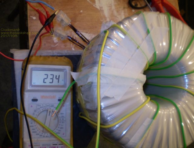 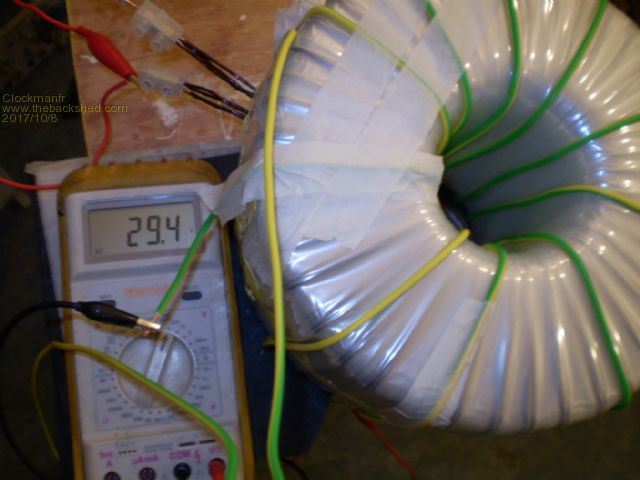 Everything is possible, just give me time. 3 HughP's 3.7m Wind T's (14 years). 5kW PV on 3 Trackers, (10 yrs). 21kW PV AC coupled SH GTI's. OzInverter created Grid. 1300ah 48v. |
||||