
|

|
Forum Index : Electronics : Warpspeed’s MOSFET mounting method
| Author | Message | ||||
mackoffgrid Guru Joined: 13/03/2017 Location: AustraliaPosts: 460 |
Yes it is over sized (x 2 I'd say) Its about 70% of the size of the core I'm using for transformer #2 but I don't have any other use for it. I worked out that the existing 32v winding I want to use has 58 turns. I figure I can easily fit another 58 turns of 4 or 5mm winding on for my new primary. |
||||
| Warpspeed Guru Joined: 09/08/2007 Location: AustraliaPosts: 4406 |
That sounds pretty good. Cheers, Tony. |
||||
mackoffgrid Guru Joined: 13/03/2017 Location: AustraliaPosts: 460 |
Hi Tony I have got my new PCB's. I got them through JLCPCB and they were great. At $27 AUD inc DHL, paid for them on a Tuesday morning and DHL delivered them Friday that week ! Its all looking good so far, just waiting to clear some room to do a real test with 3 transformers. 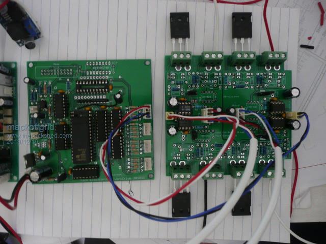 Clock Board and a Fullbridge Board. (2 Fets per quadrant) I have Half Bridge Boards also (4 Fets per quadrant ) 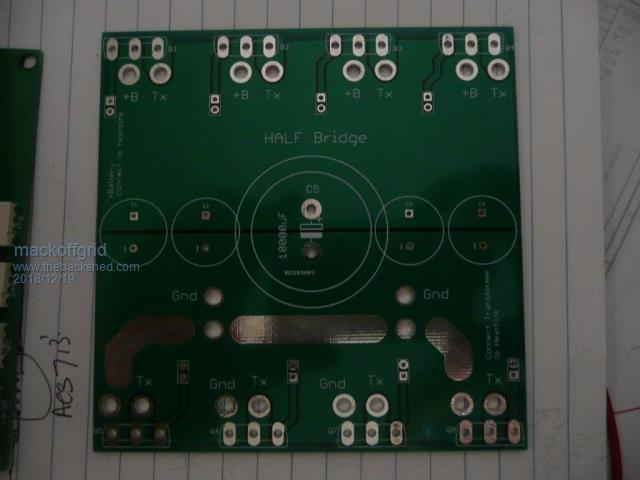 The Driver board plugs into the relevant FET Bridge board. Removing all components from the Bridge boards allows for full planes of copper for +Batt, GND, and Transformer Legs. I have done the calculations and believe the PCB should be good for a RMS current of 20 to 30 Amps per FET. Driver Board and Full Bridge pcb. 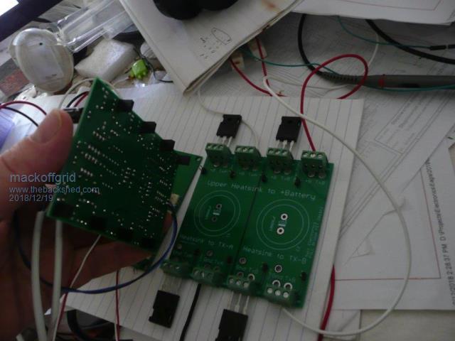 I have done the driver boards so that a driver board can drive additional driver boards. In this way my large transformer can be driven from 2 half-bridge boards and a full-bridge board to provide 6 fets per quadrant. All subsequent transformer should be able to be driven off just one full bridge board each (over kill for the 2 smallest). The Full-Bridge drivers drive the FETS from the HP3120 but will be buffered on the Half-Bridge boards with TC4452. I updated the Clock Board to take the 2 Meg eprom. Instead of using an ADC like you have, and you're implementation was very appealing, I'm still going for a processor approach, so far it'll be a nano but that could change. The main reason is flexibility. When I re-did my software for the eprom maps, I was amazed at the level of regulation this afforded me. My nom. 24V lithium bank does not vary very much, I take it up to 28v and it lives around 26.5 to 27v during the day and low 26's overnight. Given this I decided to split the eprom into 2, so 128 maps of 1k maps for increments of 25mv of battery volts. Far more than I need. The other half of eprom is dedicated to Hot water Service. My idea is that I can take information from my solar charge controller containing estimated available un-used solar power and for the inverter to deliver that available power to the Hot Water Service. As this is in an off-grid situation, this will be a big bonus to soak up all the lost energy. I used 127 maps from 100% power down to 10% power. My plan was to make this dual purpose - I could have a contactor change the output to a dedicated output just for HWS and go into HWS mode. This suits me well because I have intermittent use for the inverter to run various water pumps that I control manually (hour long runs) and can easily manage usage between HWS and proper inverter function. BTW I have a Latronics 3kW to run the cabin - and yes when we eventually build the house it will be 48 volt. (its attractive to go high voltage but for safety I'll sit with nom 48v) Anyhow, thats all for now |
||||
| Warpspeed Guru Joined: 09/08/2007 Location: AustraliaPosts: 4406 |
Coming along really well, not long now ! Yes the regulation is so fine its truly seamless. If you can correct each mains cycle for incoming voltage there will be no change in output at all for incoming dc changes. No requirement at all for PID feedback. My inverter output drops about 2v per Kw of load increase. I did not use high power gate drivers, fast gate switching is just not necessary, and slower gate drive should give better dynamic balance during switching. As a matter of interest I measured some distortion figures with an HP333A distortion analyser. One inverter 20% Two inverters 6.3% Three inverters 2.2% Four inverters 0.85% Pretty pleased with that. Cheers, Tony. |
||||
mackoffgrid Guru Joined: 13/03/2017 Location: AustraliaPosts: 460 |
I'll certainly give it a go without the 4452, I put a jumper in specifically to try that. Those distortion figures follow the logic but impressive all the same. I also figured I'd drop around your figures, probably a tad more - I have no problem with a little bit of Vdrop. (On our property we run a > 500m cable to power a 750W water pump - I worked out the acceptable Vdrop vs cost, and it turned out spot on, that was 10 years ago - no problems) I can't quite remember but I think we lose 10v on the latronics (and building cable) when we put the jug on. Tony do you have any advice on topology for a 2kW nom. 48v battery charger (up to 56V) ? I'm looking for continuous duty, rugged enough to handle a rubbish generator, reasonable noise. At first I thought using 20kHz push-pull design with 1200v IGBT , as I like the simplicity. But I have read that the noise on large push pull designs can be hard to manage (due to snubbing requirements)? I could use an aerosharp core and do a basic buck converter on the low volts but that just seems wasteful - still needs large ferrite cores and silicon. I was after continuous duty as I'm spending most of my time in the city atm and I'd like to do long term testing of a 48v inverter and rather invest in a proper battery bank, I could just use 4 crappy car batteries and a decent online charger. |
||||
| Warpspeed Guru Joined: 09/08/2007 Location: AustraliaPosts: 4406 |
The grid voltage is up and down by about ten volts here, and my house wiring drops a few extra volts too under significant loading. Very precise output voltage from an inverter is just not required. What is far more useful is very good dynamic step load performance. Things like heavy motor starts can cause lights to flicker, and that also depends strongly on the type of lighting. Most of that is not the actual inverter itself, but the huge transient start up current drawn from the dc source can create a voltage sag for a second or two while something like a large airconditioner starts up. If the inverter can correct completely (within 20mS) for any input voltage changes, it almost completely eliminates the light flicker problem. The difficulty with any PID voltage feedback is that it is going to be slow, and must be made slow and sufficiently damped for stability. Direct cycle by cycle input voltage correction will be much faster and the correction total for the next ac cycle. None of this slow ramping up and down to correct nonsense. If the dc input voltage suddenly drops by exactly 13.5% add 13.5% to the PWM or the stepped sinewave duty cycle, and the next ac output cycle should be perfect. As far as a big sturdy reliable battery charger goes, for bulk charging, I would be looking at a very basic transformer/rectifier/choke combination. If its from the grid, SCR phase control in the primary works very well and is robust and efficient. This will not work from a standby generator though, it will surge horribly so avoid that combination. Another possibility is again a crude transformer/rectifier but completely unregulated, and feed that into your solar controller in parallel with the solar panels. That should work well either from the grid or a standby generator on cloudy days. Cheers, Tony. |
||||
mackoffgrid Guru Joined: 13/03/2017 Location: AustraliaPosts: 460 |
Tony, I was going through Mikes MPPT topic and saw your post 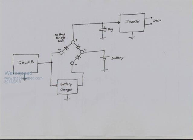 For 48V systems and above This setup allows for Larger solar Array - smaller battery installation. Given that I use 10kW solar arrays, on a sunny day, this setup will more than double the inverters source current. So when I want to start a compressor, the inverter can source current from the solar array first, then the battery. The inverter will just have to handle a more dynamic input voltage. The power loss from the rectifiers during the day is inconsequential. Obviously this won't suit those who are using GTIs to charge their batteries. There is a great allure to go for a higher voltage but 48v is benign, its been over 30 years since I've been zapped and I don't fancy a fresh experience - maybe 72 volt wont be too bad. see crazy youtube on effects of AC and DC |
||||
| Warpspeed Guru Joined: 09/08/2007 Location: AustraliaPosts: 4406 |
I still have memories of helping to launch an aluminium power boat in Port Philip Bay. Up to my knees in salt water gripping the hull with one wet had and touching a +12v dc battery terminal with another wet hand. It was a pretty nasty bite !! So I do have a LOT of respect for dc voltages, but extreme care, awareness, old age, and faith in God, have so far saved me from being fried. My system operates in a fairly unique mode, and as you say it favors a big solar small battery installation. As soon as the sun begins to have sufficient strength at dawn, battery discharge falls to zero and it begins to charge the battery, but at a low set limited current. Its set so low, that grey dismal awful days make very little difference. During the day, the inverter runs straight off the solar panels at voltages up to around 140v. Nothing at all is drawn from the battery during the day. When any one individual cell of my battery reaches 3.45v the charger shuts off, and stays shut off. My battery sees only a long slow continuous charge during the day, and one long slow continuous discharge at night. Software detects the 0v from solar at night and resets the charger for another go at dawn. Minimal battery charging current, and one continuous charge/discharge cycle every 24 hours. From what I have read, this is the very best way to get maximum battery life from Lithiums by reducing the number of charge/discharge cycles. Having the more usual tightly coupled solar controller/battery/inverter combination means that some very high currents can be shuffling in and out of the battery during the day. Charging at 80 amps one moment, and discharging at 80 amps a few minutes later cannot be good for the battery. I hope this very gentle treatment of the battery will result in extended battery life. Its going to take quite a few years to test this theory. Cheers, Tony. |
||||
mackoffgrid Guru Joined: 13/03/2017 Location: AustraliaPosts: 460 |
Merry Christmas, I hope everyone had a pleasant day. I got the inverter all wired minus the tiny transformer. No smoke escaped, no FETs were harmed :-) I did find out what the output looks like when the Medium Transform is the wrong polarity - you know I checked all the polarities twice - sheesh. Here's the output of the 3 transformer inverter (I'll now wind the 4th transformer) The Cro is connected to the output 1Meg / 100k divider. 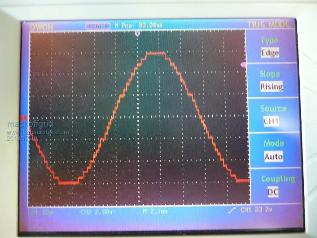 When the Inverter is running it's load increases by only 10 Watts. |
||||
| Warpspeed Guru Joined: 09/08/2007 Location: AustraliaPosts: 4406 |
Yes, Merry Christmas to everyone. Your idling current is pretty low too, quite comparable to a good PWM inverter. So a few minutes ago, just for fun, I disconnected my fourth smallest inverter, and shorted out the primary. This is with a x100 probe poked into the active of the nearest power point. The rest of the house is still running off this too, including some fairly reactive loads which can introduce extra distortion onto the step edges. A fairly drastic two stage EMC filter I have on the output also adds a few reactive effects of its own, and visibly slows down the edges. What you are seeing on yours looks to be just about right. An EMC filter on the output might reduce some of that high frequency fuzz. Not sure what that is, but it could possibly have something to do with oscilloscope grounding, it might not really be there... 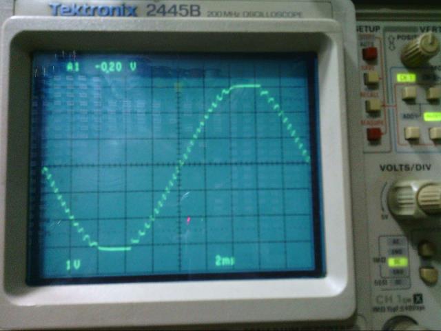 Here it is with the fourth inverter connected back up again, with the same EMC filter on the output. Rather a big difference as you can see. I fully expect that yours should look about the same once you have the little #4 guy running as well, its well worth the extra few parts. 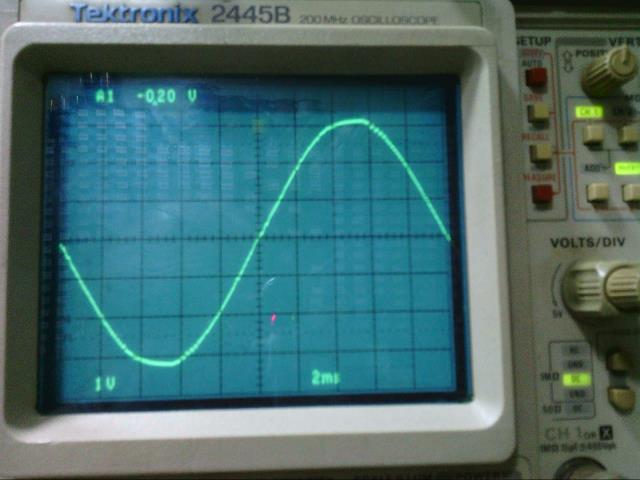 This is what the grid is doing here right now. 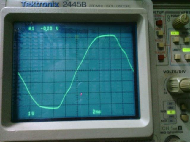 Cheers, Tony. |
||||
mackoffgrid Guru Joined: 13/03/2017 Location: AustraliaPosts: 460 |
Hi Tony This will be going into an existing 24v system. This is my FET_Bridge board setup on it's heat sink. The first transformer is driven by the first 3 boards, which are half bridge + full bridge + half bridge. The rest of the transformers are driven by one full bridge board each. 10,000uF caps (x4, one each on the first 4 boards) are mounted underneath the boards. The FET boards with their driver boards plugged in. The Fets driving the 2 smaller transformers shouldn't need big heatsinks so I'm just using the heavy AL angle. Next will be the Bench Test .... Cheers Andrew |
||||
| Warpspeed Guru Joined: 09/08/2007 Location: AustraliaPosts: 4406 |
Its interesting that although this type of inverter has a great many individual parts, it really lends itself to modular construction, as its really just repetition of really simple circuitry. Cheers, Tony. |
||||
| LadyN Guru Joined: 26/01/2019 Location: United StatesPosts: 408 |
Looks beautiful! I would really appreciate looking at pictures of one completed unit and the specs of it. I think it should be in its own separate thread :D |
||||
mackoffgrid Guru Joined: 13/03/2017 Location: AustraliaPosts: 460 |
Hi N, I did think about a new thread but there is a lot of context in the history of this thread and I thought it would be better to keep it all together. ? |
||||
mackoffgrid Guru Joined: 13/03/2017 Location: AustraliaPosts: 460 |
I haven't made the final enclosure for it yet but it will be a welded frame, with rear wheels that I can wheel into position using slip in handles much like a wheel barrow. I expect this to be around 60+ kg. I did a bench test of the inverter this morning. Limited test because: - I only have 2 largish wheelchair Gel Cells. - I'm using 2.5 mm2 building wire to supply battery and to connect the large transformer - didn't want to cut up good cable until it gets into its new box. The results was a bit surprising. I'm getting a High Freq ringing that wasn't present in the last test, the main difference are the 10000uF caps on each of the boards, of the 2 bigger transformers. The following scope shots are using a 10:1 divider. Previous 3 Tx test - No Caps 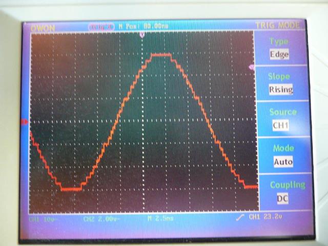 4Tx tests - with Caps No Load 150 Watt Load 550 Watt load It looks like the switch on of the big transformer is the culprit, I lowered Rg from 100R to 50R - maybe I should put it back. Tests went well otherwise, the batteries dropped into the 23 volt region but the inverter had no issues. No Load power of the transformers was only 10 Watts. Nice. Cheers Andrew |
||||
| Warpspeed Guru Joined: 09/08/2007 Location: AustraliaPosts: 4406 |
The more I think about this, the more it looks like a power supply impedance problem. What does the +dc power rail look like with that ringing ? Apart from the spikes (which we will fix) that is a nice smooth sine wave underneath. That no load power is INCREDIBLE, well done ! Cheers, Tony. |
||||
mackoffgrid Guru Joined: 13/03/2017 Location: AustraliaPosts: 460 |
Hi Tony, you may well be right. This is no load. Rg is now 100R. No difference to the output, maybe worse. I should do this again with ch2 on the drive signal but this was quite repetitive and I think obviously related to that spike. I'm amazed at the tidyness of it. One 5v pulse down and one up. I've had the caps for a couple of years, Rubycon brand, but got them through AliExpress. |
||||
mackoffgrid Guru Joined: 13/03/2017 Location: AustraliaPosts: 460 |
I'm assembling some more FET bridge boards so I can use a single full bridge board to drive the main transformer during testing. I'll do more test in the coming days. Tony, I've been thinking about my next inverter. Its a new off-grid install. If say it was to be nominal 96v (using diode isolation so I need Vmax of 160+ volts). I could use the IGBT modules from the aerosharps for the main and 2nd transformer. I probably would have stuck to mosfets but I have a bundle of those modules. I presume they are still functional??? I was going to gun for 6kw-ish (cont) for the 96v beast so I thought I could use 3 modules for the main Tx and one for the 2nd Tx. Plenty of headroom for starting compressors and other workshop equipment (like a car hoist). The Heatsink is electrically isolated so I could mount all the modules on one heatsink - if they fit. 2019-02-22_161002_pm50b4la060_e___Power_IGBT_module_from_AeroSharp_GTI.pdf App Note The reality is that the inverter will run at around 300 to 600 watts most of the time and a couple of hours at 3.6kw for hot water, and summer may go to 1.5kw during the day for Air-cond. What has your experience been with the extra heat generated by the IGBT's? Cheers Andrew |
||||
| Warpspeed Guru Joined: 09/08/2007 Location: AustraliaPosts: 4406 |
Andrew, that is pretty much exactly what I have done. One electrically isolated heatsink for everything. My experience is that at low power the conduction losses will be just about zero with either mosfets or IGBTs. But it gets a lot more interesting at higher power. The voltage drop across IGBTs will not typically go much over about 2v no matter how much current there is. So heat dissipation becomes roughly directly proportional to current. The (I squared R) voltage drop across mosfets will be current squared, so the heat dissipated rises square law with current. If you are pushing really high power that can get pretty high rather quickly. And it can become fatal for any really high surges or fault currents. The big old and slow 200 amp half bridge IGBT power blocks I am using are rated for a full 1,000 amps half sinusoid 10mS of fault current. Way beyond anything mosfets could survive. Just about impossible to pull them out of saturation. Not suitable for PWM though, as they are just not fast enough. But for switching at a few hundred Hz or less they are ideal for an application like ours. I have four 24v solar panels per string. Max open circuit voltage about 145v, maximum peak power point around 120v although the power "peak" is actually a rather broad hump. Battery is thirty 3.3v lithium cells. Fully charged 103.5v down to about 98v at night. Inverter is designed to work between 90v and 180v. I use IGBTs in the two larger inverters and mosfets in the two smaller inverters. Average power long term probably not much over 200 watts here, but it will run a 2.5Hp air conditioner continuously at 4.8Kw very easily. I really do not have enough solar or battery to run the inverter at that kind of power level for any length of time. More solar in the future should fix that, but the inverter handles it easily. If you are going to wind another set of transformers, an electrostatic screen might be worthwhile to block any spikes caused by primary/secondary capacitive coupling. Pretty sure that is not your problem now, those spikes look a lot higher than the 24v you have on your primary. But screens are some extra insurance when you go to a higher dc input voltage. Cheers, Tony. |
||||
| kanchana Regular Member Joined: 08/05/2018 Location: Sri LankaPosts: 56 |
I have 48v leaf module setup (aiming to operate between 57.5 to 55 volts ) what kink of circuitry should involve the battery charger in Tony's configuration Regards kanchana |
||||