
|

|
Forum Index : Electronics : 8 KW Inverter Build
| Author | Message | ||||
oztules Guru Joined: 26/07/2007 Location: AustraliaPosts: 1686 |
Tinker... yes and no. They both use the CT as a floating gate drive, but yours is more sophisticated. Mine shuts down the drivers ( SD on yours?) and the temp pin ( TFB). IFB not used. Will scribble out a circuit maybe tomorrow. Who would have believed we could build simple pure sine inverters, that will easily out- perform most inverters on the market, and start things most off grid folks only dream about. ..........oztules Village idiot...or... just another hack out of his depth |
||||
Madness Guru Joined: 08/10/2011 Location: AustraliaPosts: 2498 |
I have tried the various dead time settings, no noticeable difference apart from reducing the little blip. Quite easy to do just remove pins 1 & 2 from the adaptor Board and add short wires on top to each hole. Then solder to pin 3 for ground or 26 for 5V. The blip is still there, I will work on getting the board completed tomorrow as I have the day off and get it into the case. There is now 20 MOSFETs on the board and running just the same as photos above at idle. Once that is done I have 4 heaters ready to give it a decent workout. I tried it again tonight with 1 fan heater and the FETs are barely above ambient. Just went to take photo's but camera batteries are flat so will get pictures tomorrow. Yes Oz, I am starting to believe it works, been running all day again on idle plus a few periods of 2200 watts and still behaving itself. Will be good to be able to use my abrasive saw off the inverter, my Trace Inverter just says no way and turns off. Also look forward to giving 240 amp MIG welder a try on it also. I am still amazed at how you got it all to work so easily. There are only 10 types of people in the world: those who understand binary, and those who don't. |
||||
oztules Guru Joined: 26/07/2007 Location: AustraliaPosts: 1686 |
You have suffered enough..... no migs until we get a current control up there. I also now use the big 2.7mh chokes from the aerosharps built into the mig now to limit surge.... saves any o/loads, and smoother welds. If you read my early stuff on the original experiments.... I was gobsmacked at how powerful and stable these things were.... was just lucky it was like that. If I had been made to suffer like you.... I think I would have just given up long ago. ...........oztules Village idiot...or... just another hack out of his depth |
||||
Madness Guru Joined: 08/10/2011 Location: AustraliaPosts: 2498 |
Been trying to work out why it has been such a rough road to here. Having the wrong values on the snubbers caused a chain of events. Not having a working CRO back then was like trying to do it blindfolded. It's been running 2 days now, will see how I go today, might be turning off the old Trace and connecting this monster to the house. I forgot to mention I tried the cable I made to replace the ribbon cable, it made no difference. There are only 10 types of people in the world: those who understand binary, and those who don't. |
||||
Madness Guru Joined: 08/10/2011 Location: AustraliaPosts: 2498 |
Just been looking at the EG8010 Datasheet , if you are using Bipolar you will then also need to two filter chokes as shown on page 13. There are only 10 types of people in the world: those who understand binary, and those who don't. |
||||
| ryanm Senior Member Joined: 25/09/2015 Location: AustraliaPosts: 202 |
I've seen a whole bunch of these around here lately and they look pretty alright. Does anyone know a rough figure of how much it would cost to source all the parts to put one together? |
||||
Madness Guru Joined: 08/10/2011 Location: AustraliaPosts: 2498 |
Hi Ryan, Apart from buying the dead Aero-sharp Inverters which I got for $65 each. Total cost of parts would be around $200 - $300 AUD depending what you can scrounge up, particularly when it comes to high current cables and breakers. You can order instruction and PCB's from Clockman , or do the research of various threads and make your own from scratch as I did. I thought I might save a few dollars doing that but it has cost me a lot more in trial and error. So if you allow a budget of $500 you will end up with a serious inverter that will run your whole house. That includes AC, hot water, oven, electric cook top, water pumps, washing machines etc... If you do not have an Oscilloscope already it would be a good investment to get one also, I bought one secondhand recently for $100. There are only 10 types of people in the world: those who understand binary, and those who don't. |
||||
| Tinker Guru Joined: 07/11/2007 Location: AustraliaPosts: 1904 |
Thanks for that tip, I will also try the chokes on my PJ based inverter which runs anything, except my 175A inverter MIG welder, at my place. Funny thing, it runs the old 125A stick welder. Klaus |
||||
oztules Guru Joined: 26/07/2007 Location: AustraliaPosts: 1686 |
From memory, your running the little 8kw board. If you bypass some current around the CT it will run the welder natively... or change the shunt resistor on the CT. The 8 and 15kw boards are identical electrically, but for the shunt resistor on the 15kw for more power. Physically the 15kw power board has bigger sinks and extra caps. .........oztules Village idiot...or... just another hack out of his depth |
||||
| Tinker Guru Joined: 07/11/2007 Location: AustraliaPosts: 1904 |
Thanks, but its a bit complicated to do that. The 8KW PJ board based inverter runs my house now and taking it apart to get to that shunt resistor is a big pain in the back side. That is one reason why I'm tackling another inverter project. Another reason is, I like that kind of challenge  . .Getting it going soon - I hope  . . Klaus |
||||
Madness Guru Joined: 08/10/2011 Location: AustraliaPosts: 2498 |
Finally, some success to report, been chasing why the waveform was distorted. I found 1 pad on a MOSFET gate had a partial solder bridge leaving a gap of about 0.5mm. Still not as good as I would like as you will see below but it is running. Here is how it looks now 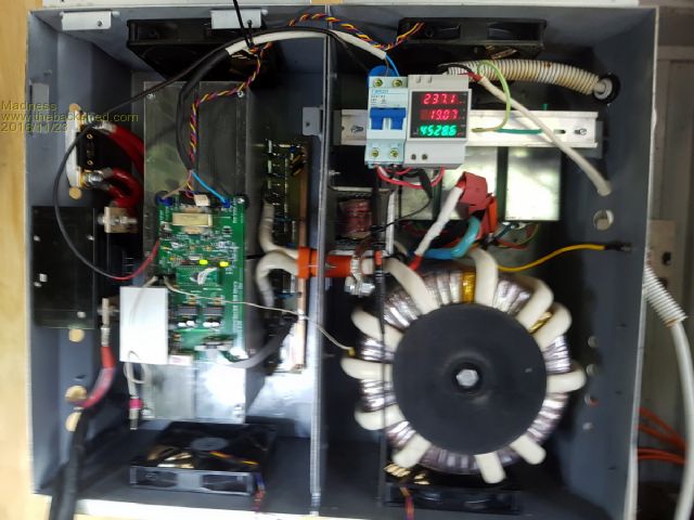 As you will see I have changed the primary to 70mm square welding wire which made no difference, I was chasing the cause of bad waveform which is why it was changed. Here it is under load 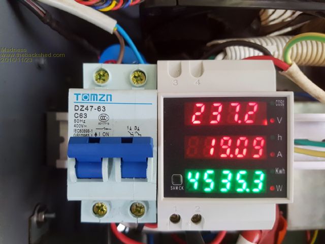 Started out with no fans and ran for over 20 minutes before I temporarily got the 2 fans in the bottom of the case running. Here is temperatures of the FETs and Toroid before I started the fans. 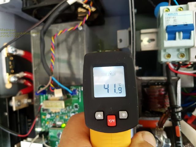 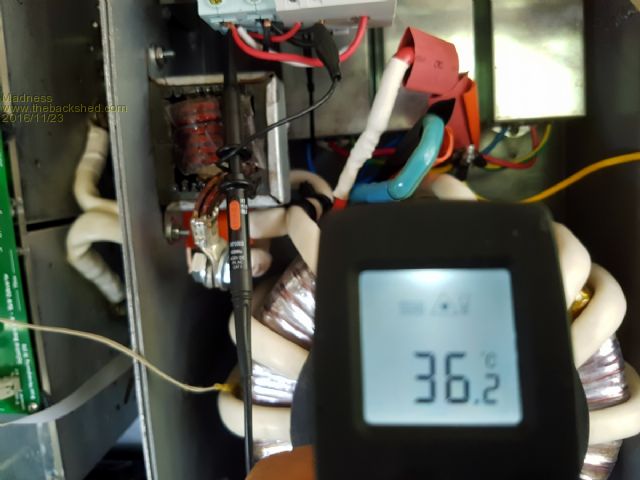 There are only 10 types of people in the world: those who understand binary, and those who don't. |
||||
Madness Guru Joined: 08/10/2011 Location: AustraliaPosts: 2498 |
After running for half an hour and the fans now on here are the temperatures. 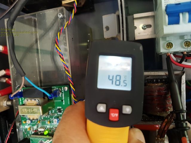 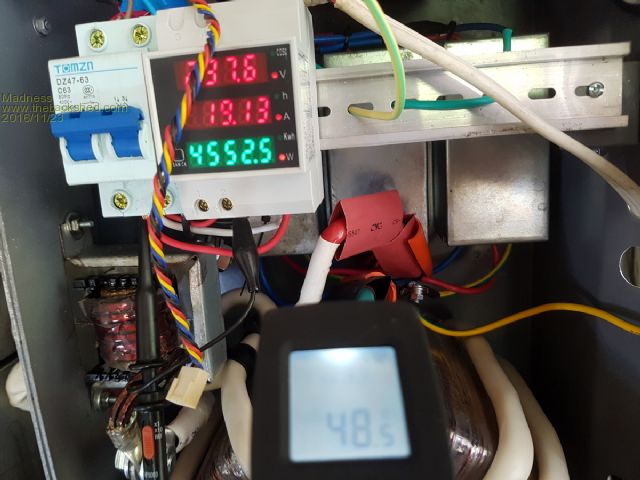 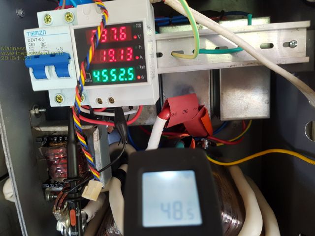 Here is the ambient temperature. 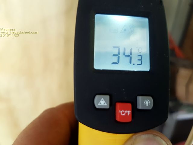 This is with only 2 fans in the bottom running, next stage is to get a fan controller running and make a cover for the front. There are only 10 types of people in the world: those who understand binary, and those who don't. |
||||
Madness Guru Joined: 08/10/2011 Location: AustraliaPosts: 2498 |
Any opinions on the waveforms would be appreciated, with no load I get very crisp narrow wave with just a tiny bit of a squiggle after crossing zero on the bottom half of the wave. However, a load of 1200W or more give the result here. 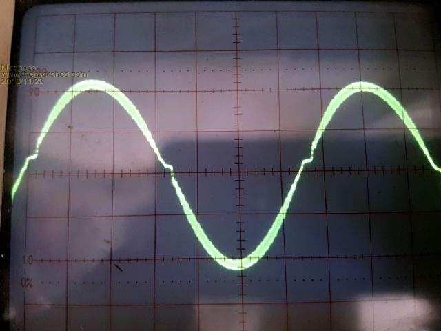 This is with 0.1 mS per division, I have tried with 2uf and 5uf caps with no difference. 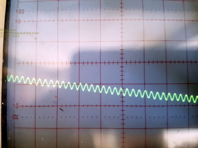 It is running quite well apart from the waveform concerns, I also have increased the dead time to 1.5uS to reduce the blip at zero crossing. There are only 10 types of people in the world: those who understand binary, and those who don't. |
||||
oztules Guru Joined: 26/07/2007 Location: AustraliaPosts: 1686 |
What was the waveform at standard deadtime before you changed it... better, worse, same ( not the squiggle part... the fluffy part) You gotta be happy seeing over 4kw for 30 mins or more, and less then 50c with 35 ambient.... I keep forgetting I live in an ice box comparatively, and my heat sinktemp would have only been less than 35c or less on most days.... @ 4kw for that unit. Lost for the cross over reasons... wondering if it is the gap of the the cores perhaps? did it do it with the single core?. Sounds like it is not a problem though..... 4kw and not excessive heat, it is running good enough to be very pleased. Good to see sturdy operation, and good temp figures... one wonders why the troubles in the first place. How much better is the trace wave at 4kw? Well done. ..........oztules Village idiot...or... just another hack out of his depth |
||||
Madness Guru Joined: 08/10/2011 Location: AustraliaPosts: 2498 |
Hi Oz, The wave is the same at standard dead time apart from the blip. I get the same on single core also, the rewound double is very quite now. What is noisy though is the choke, I am wondering if it is causing this. It is super glued together but is it stuck properly in the middle, I have all the bits now to put together another one. So I will try that as soon as I get time (after getting fans working). Yesterday I ordered a 100mm x 65mm x 20mm Ferrite Ring on Aliexpress I see you use them quite a bit, is 3 turns still the best on them? It has been hot here the last few days and supposed to be hotter today before a change comes through. If I pick up a cheap second hand AC it will be going on the shipping container that has all my solar equipment in it. Once I get the fans working I will connect the Inverter to the house. The transformer runs warm even at idle, is that normal, it is drawing around 1A with no load. The old Trace Inverter has a much uglier waveform steeper angle on one side and lots of steps, but it is very narrow and crisp. I will get a picture of it sometime. I have a transfer switch to install also, like a standard 63A breaker but double the width, it has 2 inputs and one out and will not allow both to be on at the same time. Then I can easily switch Inverters while still getting this one completed and working right. Yes very happy to see it running strong now, no drama it just does the job. Still waiting on logic level MOSFETs (FQP30N06) to turn up for my Arduino based fan controller and data logger. 45 Days now and 30 days since any change on the tracking, I have ordered more from elsewhere. Now when I order from Aliexpress I order from 2 different suppliers to make sure stuff arrives in a reasonable amount of time. There are only 10 types of people in the world: those who understand binary, and those who don't. |
||||
oztules Guru Joined: 26/07/2007 Location: AustraliaPosts: 1686 |
Ferrite ring.. I only have used one thus far, and 4 turns on that, ecore is about the same, but silent torroid. Do you have any idea/ can you put the finger on.... why it has been so tough on you (now that you seem to have turned the corner)? Have you thrown everything at it yet? or have you been pussyfooting around with it. ......oztules Village idiot...or... just another hack out of his depth |
||||
Madness Guru Joined: 08/10/2011 Location: AustraliaPosts: 2498 |
Still pussy footing, don't have the fans setup yet. I made 2 of your temp fan boards last night etched them, drilled them, went to put the components on and they where f  ing mirror image of what they should have been. I will have it sorted out on Saturday, I have 4 10A heaters ready to go, just what I need in this hot weather. ing mirror image of what they should have been. I will have it sorted out on Saturday, I have 4 10A heaters ready to go, just what I need in this hot weather.Problems started I think with wrong snubbers, that also damaged control boards. Not having a CRO meant I was feeling my way in the dark, also had a bad batch of IR2110. Another issue was a tiny fleck of copper between a track from the H-Bridge and a gate drive track. It did not show on my meter, took a while to find that one, the Lanox on the board was holding it there. That caused a few FETs to die. Previously you told me to hold off on hitting it hard with the MIG welder till I have your new design for the control board.  There are only 10 types of people in the world: those who understand binary, and those who don't. |
||||
oztules Guru Joined: 26/07/2007 Location: AustraliaPosts: 1686 |
I fully expect you can replace the trace with it, and see how it goes running the house.. should do just fine. The big mig I have can do some enormous spikes ... must be in the 20kw ranges. so thats why I am suspicious of it. Will finalize the board soon ... time ... always time.... .......oztules Village idiot...or... just another hack out of his depth |
||||
Madness Guru Joined: 08/10/2011 Location: AustraliaPosts: 2498 |
Yes I have no doubt it will do the job the 4.5KW Trace is doing now, I just want to get the fans working first. Especially with this heat we are having ATM 10 degrees above average. I have no plans to do any welding this year. There are only 10 types of people in the world: those who understand binary, and those who don't. |
||||
Madness Guru Joined: 08/10/2011 Location: AustraliaPosts: 2498 |
Changed the Choke today, it made no difference. Also got 2 temp_fan boards running as well, I put the 4.5KW load back on again today and the fans kicked in after about 5 minutes. They are truly temp_fans though as I will be changing it to the Arduino based controller/data logger when I have that completed. Took a bit to track down the Temp_fan board so here it is. 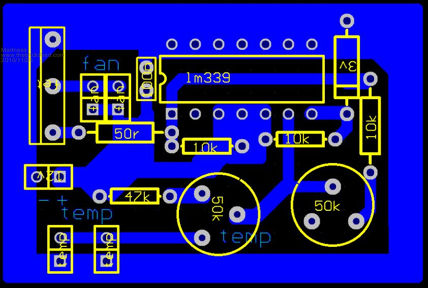 2016-11-26_073725_TEMPFAN2_2.pdf I will be connecting it to the house in the morning, got a little late in the day to do it today, I have a transfer switch to put in also so I can easily go back to the old Trace Inverter if needed. Also, I will try some bigger loads than and see how it performs. There are only 10 types of people in the world: those who understand binary, and those who don't. |
||||