
|

|
Forum Index : Electronics : building an Inverter from scratch
| Author | Message | ||||
oztules Guru Joined: 26/07/2007 Location: AustraliaPosts: 1686 |
gee.. looks very very nice.... only a little bit green here..... ok a lot green here 
......oztules Village idiot...or... just another hack out of his depth |
||||
fillm Guru Joined: 10/02/2007 Location: AustraliaPosts: 730 |
Hi Klaus Ditto here as well , very nice work and will following down the same road when I get back to mine after a bit of a roofing project, but for the meantime I will just as dumb questions in the background. Until I get back will keep watching and taking you tips onboard. I still would raise the concern on cooling these but I suppose it comes down to how hard you are going to drive it and the efficiency. I have bought some heat shrink mylar tape from the US to hopfully help keep the wires in place and tight. Is Kapton tape the same as Mylar ? PhillM ...Oz Wind Engineering..Wind Turbine Kits 500W - 5000W ~ F&P Dual Kits ~ GOE222Blades- Voltage Control Parts ------- Tower kits |
||||
| Tinker Guru Joined: 07/11/2007 Location: AustraliaPosts: 1904 |
I dunno. I just recycled the clear 12mm tape I had unwound from the donor toroid. I assume its mylar but I could be wrong... On my original inverter project (tinkers inverter project) I eventually ran out of that recycled clear tape as more layers of wire were wound on. Rummaging in my tape box I found some black heat shrink tape. It was not very strong but possibly OK for the smaller wire size. Too weak IMO for the bigger primary wires I used. The twine tourniquet I described above works very very well to tighten the outer part of the winding's. Additionally, epoxy the inner part as I described and you get a silent transformer. If you are unfamiliar with epoxy let me know and I pass on some hints. Klaus |
||||
fillm Guru Joined: 10/02/2007 Location: AustraliaPosts: 730 |
Hi Klaus, yea all good on the epoxy and glass thing as have used it on many occasions with the AXFX. That's why I questioned its use when there is a issue with heat and cooling. But it seems its benefits out weigh its disadvantages. This mylar tape I have coming is oven baked and I think it shrinks by 20% Link Not sure if that link will work . PhillM ...Oz Wind Engineering..Wind Turbine Kits 500W - 5000W ~ F&P Dual Kits ~ GOE222Blades- Voltage Control Parts ------- Tower kits |
||||
Madness Guru Joined: 08/10/2011 Location: AustraliaPosts: 2498 |
Kapton tape is Adhesive, at least any that I have used is, the mylar has no Adhesive. I used Kapton tape to finish off my Torroid. When soldering connectors on I used a small gas torch, the heat from it had no effect at all on the Kapton tape or mylar that came off the original Toroids. With that string wrapped around the toroid, I would be concerned that would act as blanket and keep the toroid warm. There are only 10 types of people in the world: those who understand binary, and those who don't. |
||||
| Tinker Guru Joined: 07/11/2007 Location: AustraliaPosts: 1904 |
Madness, that layer of string is now buried under the copper foil static shield which also acts as a "blanket". But, I overbuilt the conductor area on my toroid, these have way more mm sq than on yours. The secondary is 10mm sq and will see only seconds of 30A during its use, most of the time <10A. Keep in mind that 30A @ 230V represents 6.9Kw. My battery bank (200Ah/48V) is not large enough to sustain that for long. The primary is going to be 90mm sq, possible the biggest wire section of any toroid build mentioned here. I very much doubt that there will be *any* expected current load heating causing my toroid transformer to get warm. But, just in case, the fan blows directly onto it  . .Klaus |
||||
Madness Guru Joined: 08/10/2011 Location: AustraliaPosts: 2498 |
I see, my battery bank is 1600 AH combined with 7.5 KW of PV panels that will eventually increase to well over 10 KW. The inverter I am using now quite often is running close to 20A @ 230V, once I complete my Oz inverter and connect air conditioning to it, 30A plus will be very regular. Also, I run the 2400 watt heater in my hot water system off the inverter, add to that refrigeration, oven, front load washing machine with a heater, etc. 40A for 30 minutes or more will be a regular event. Particularly when there is plenty of sunshine as I am aiming to have enough PV panels to carry us through any weather conditions. It will be interesting to see how you go getting all that wire in, as the more you wind on the hole increasingly decreases in diameter. I see where others have had little room left with less wire, particularly with the heavy single wire for the primary. With 21 X 11 turns of 2MM for my primary, there was a lot of scope to have quite a bit more copper in the hole. If I ever wind another, I will put more wire in it. There are only 10 types of people in the world: those who understand binary, and those who don't. |
||||
| Tinker Guru Joined: 07/11/2007 Location: AustraliaPosts: 1904 |
Yes, your system is a lot bigger than what I have here. But for this one person household 3Kw of solar and 10Kw battery storage seems to be enough. Today I have finished 3 hands (45mm sq) of the primary and the hole in the center is now 65mm diameter. I should think it will not shrink below 50mm diameter when the next 3 hands are wound on. I think your toroid is wound a bit on the light side for your expected loads. I can now fully understand now your overheating worry. I did some calculations to put my mind at rest: My 10mm sq secondary measured 82mOhm (0.082Ohm). I did measure that with a 4 wire milli Ohm attachment for my digital multi meter. So, with a 5Kw load (21.74A @ 230V) there is a 1.78V drop on the secondary winding, corresponding to a copper loss of 39W. The magnetizing loss, at 29W, is very near its optimum range and stays constant. This gives a total loss of 68W @ a 5Kw load with my toroid. I should hope that this great lump of material can easily dissipate that, especially since its unlikely to be running on that load for long. With just a 2,2Kw kettle load, the copper loss in the primary drops to 8W, giving a total of just 37W of heat that toroid has to dissipate. The primary copper loss I could not measure, it is that small. As the wire there is 5.25m long and 90mm sq, an equivalent gauge wire on my list shows 1mOhm (0.001Ohm) for the primary. I think I can ignore that. These transformers run at over 98% efficiency if one keeps the copper losses down. I had a look at the old Aerosharp enclosure as I believe you plan to use that. My toroid would only just fit inside width and height wise, a real shoehorn fit. I remember having trouble getting a single stack core in there. Also, you might have to use that enclosure on its back rather than hanging it as I think hanging the double stack weight from that single bolt is pushing luck a bit. So, if I were you, I would not re use that case, it is just too tight especially for your loads. You'll have to run the fans non stop to keep it cool. It will also be tight to re fit the mains chokes (you'll need two of them) in there. I made up a sub board to mount the chokes on, with capacitors too, to make a high current mains filter. All should fit very nicely in the enclosure I choose to use, with the toroid sitting upright on the bottom and cushioned by some cork tiles. The central bolt just needs to stop it sliding around. More about that later. Klaus |
||||
Madness Guru Joined: 08/10/2011 Location: AustraliaPosts: 2498 |
I have been rethinking my plan to squeeze it all in one Aero-Sharp case, the part that would have the biggest effect on space is the filters, 3 of them need quite a bit of space. When I get some time I will be looking at cutting off the part that hangs lower in the original installed position where the PV connects in. Then attaching it to another complete case. The reason I have thought to do it that way rather than Oztules 2 cases bolted together is so I can still have the original heat sink on the outside. Also, I may drill some large holes, maybe 50 mm to force air from inside the case out through the fins of the heatsink. Supporting the weight of the torroid has crossed my mind also, I could make a supporting brace for the bolt out of PVC, it can't be metal as that would create a short circuit turn. Another option to cool the toroid is to put it in a tank of transmission oil. Before I try that though I will be trying it with air cooling. The other day I was doing some testing with a single core with one set of original windings still on it and 2 in hand 1.6mm diameter wire as a primary. After running for over half an hour at 4.7A @ 230V the wire was over 80 degrees, there was no effect on the mylar. One day I will try it again with more power and see what temperature things started to fail. There are only 10 types of people in the world: those who understand binary, and those who don't. |
||||
| Tinker Guru Joined: 07/11/2007 Location: AustraliaPosts: 1904 |
Another progress report, my gigantic toroid transformer is now finished   . .
For the primary winding I managed to get 3 x 5 mm enameled copper wire. A company nearby makes that to order (any size) but one has to buy quite a lot... But, they seem to make a little more than has been ordered and these 'end of reel' leftovers I can get at an acceptable price. There is a catch though, this time they would not cut what I wanted (I required ~5kg) but I'd have to take all the leftover on the reel. For the 3 x 5mm wire this was 9.5Kg, a little more than I required... hmmmmm. A quick calculation showed that this amount of enameled wire was still more than $100.- cheaper than buying 24m of 20mm sq multi strand cable at trade price from Altronics.That would give 80mm sq at 4 in hand x 11 turns. So I got twice the wire for much less  . .
The plan was to do wind 6 in hand of 15mm sq. for a 90mm sq primary. This wire, at 3mm thick, is about the max thickness easily bent around the core. That stuff work hardens real quick and one has to get it right first go. This is how I started: 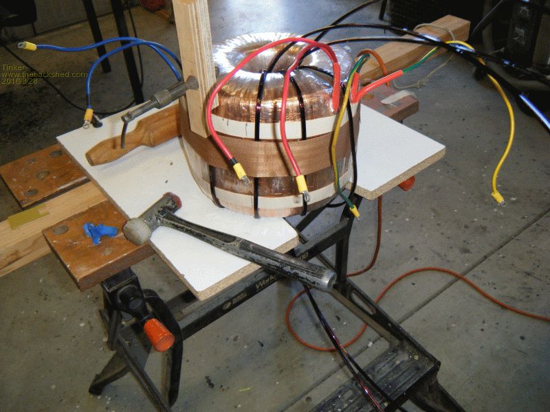
The hardest part were the first two or three turns, the wire end (which I pre tinned) has to be held firmly in place to prevent it slipping. I used a 50mm belt to hold the first few turns in place around the core. After the first 'hand' is wound on the next 'hands' can then be clamped to the first, making that job easier. I cut the first wire a little longer than calculated so I then had the exact length for the next 5 'hands' with practically no waste off cuts. 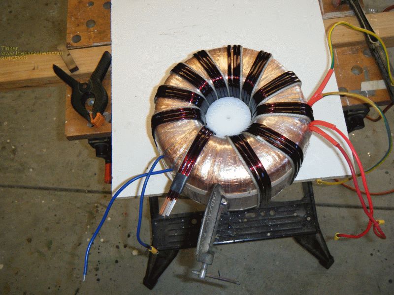
3 in 'hand' wound on. The VB cord seen sneaking around the core is there to even out the wire spacing in the hole. This needs to be a smooth surface for the next 3 in 'hand'. I wrapped more mylar tape over the first layer. The wire is hammered (plastic face hammer) around the top and bottom and I did not want to have it dig in the layer below there. 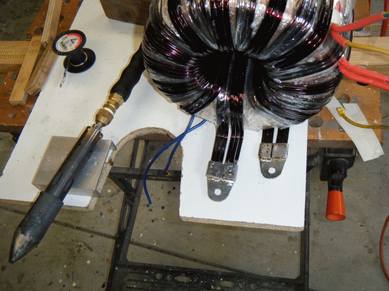
All 6 'hands' are now wound on, I used home made terminals at the ends. These were easily soldered with that giant gas soldering iron lying at the core side. 
Now another epoxied twine tourniquet was wound on to finish it off neatly. The greyish disk under the core is actually a ball bearing turntable which makes moving the heavy core around a little finger job. 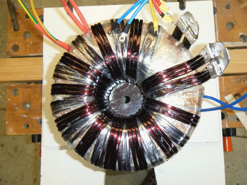
In the core center is a 16mm thick x 58mm diameter phenolic disk, epoxied in permanently. Its purpose is to center the mounting bolt. This toroid sits upright in the bottom of the enclosure, it is far too heavy to hang from a central bolt a la Aerosharp style. 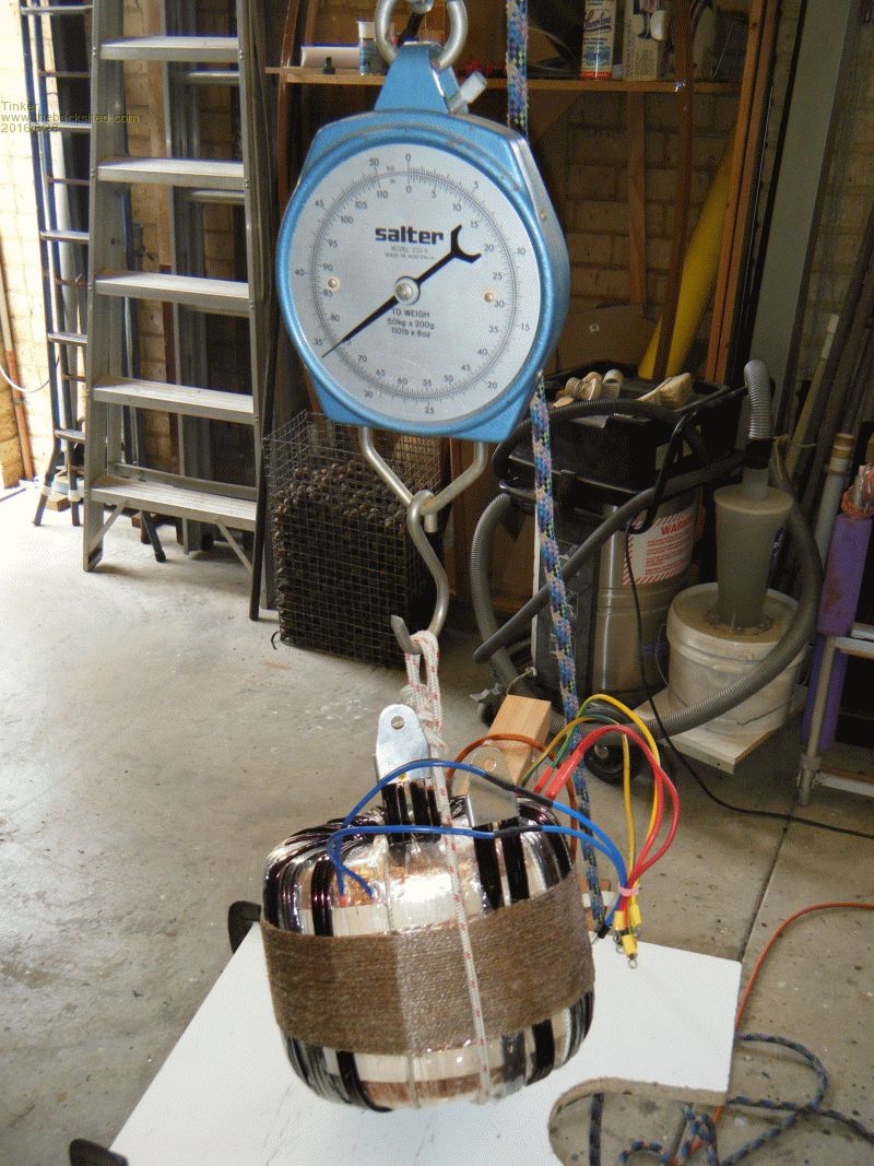
And here it is, all 34 kg of it  . .
Now I still have to make the primary chokes (I have 3 different ones to experiment) and then the testing can begin. The enclosure is just about finished too, the end of this built is in sight. Klaus |
||||
Madness Guru Joined: 08/10/2011 Location: AustraliaPosts: 2498 |
Looks very good Klaus, I would have used similar copper for the primary but I could not find anywhere to buy except huge rolls, so that is why I went with the 21 X 2 mm wire. I was trying to get 15 X 3 mm flat copper and wound just 2 in hand. I would be interested in buying some of your leftovers for making chokes if you are wanted to part with some. There are only 10 types of people in the world: those who understand binary, and those who don't. |
||||
| Tinker Guru Joined: 07/11/2007 Location: AustraliaPosts: 1904 |
Thank you madness, I think it looks the part too  . .
I doubt you would have had success to wind 15 x 3 mm copper by hand in the relatively tight curved center hole of that size core. I think around 3mm x 8mm will be the limit that's doable by hand. Actually, winding 6 in hand (one at a time  ) was a good choice with that wire size IMO. ) was a good choice with that wire size IMO.
With regard of leftover wire, I have unwound it from the drum into a 900mm diameter coil to make it easy to roll straight on the floor to measure. Sending that size by mail is impracticable and winding it smaller would work harden it to the extend of being useless for the tight choke turns. Better wait until I finished with my choke experiments, there might be then some already wound leftovers. The ones I had previously (tinkers inverter project) were snapped up by fillm a while ago, they only cost him postage & packing. If my experiments are successful I could wind quite a few choke coils with that leftover wire, lets wait & see. They would be in the 60mm sq range, no room for a bigger section on these ferrite cores unfortunately. Klaus |
||||
fillm Guru Joined: 10/02/2007 Location: AustraliaPosts: 730 |
Hi Klaus, Very nice job is all I can say and I doubt there will be another like this  . I am not sure when I will get back to mine as I am in the process of adding some more under cover space.... concreting and roofing. I know what I would rather be doing. Anyway it will be interesting to see this transformer fire up and what it can comfortably do. . I am not sure when I will get back to mine as I am in the process of adding some more under cover space.... concreting and roofing. I know what I would rather be doing. Anyway it will be interesting to see this transformer fire up and what it can comfortably do.
Phill PhillM ...Oz Wind Engineering..Wind Turbine Kits 500W - 5000W ~ F&P Dual Kits ~ GOE222Blades- Voltage Control Parts ------- Tower kits |
||||
| Tinker Guru Joined: 07/11/2007 Location: AustraliaPosts: 1904 |
A tiny bit more progress and some ideas: Messing about with connecting and disconnecting a big inverter from my battery bank I have to remember to be careful and use a resistor to pre charge the capacitors else there is a big "splat" and possibly spot welded terminals. Well, I got sick of that and made this: 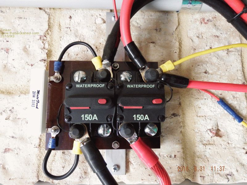
The resistor (salvaged off the Aerosharp board) is permanently connected across one battery isolator switch. So, with both switches open, first the positive SW is closed. At this stage the inverter's capacitors begin to charge up, I count to five and close the second switch. No "splat"  and I can now turn on the inverter. and I can now turn on the inverter.
For those without a clamp Ampmeter, once both battery isolator switches are closed that resistor can be replaced by an Amp meter to measure the idle current - make sure no load is connected to save your amp meter fuse. Measure the current after opening that switch. Also, close the switch and replace the resistor immediately after the measurements. That nice big Aerosharp heat sink has an annoying flaw, it is mounted from the back side. It was hard enough to remove those screws in the original enclosure and I was not going to put up with that idea on my new dual stack inverter. So I mounted the heat sink on a back plate, made from 2mm aluminium: 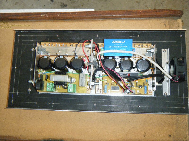
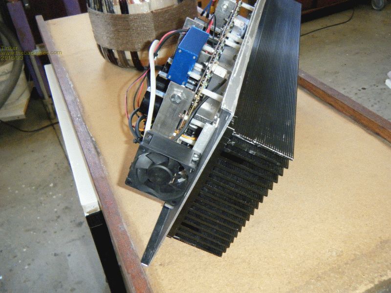
The entire heat sink pokes through a cut out in the enclosure and is screwed on from the outside. No more fiddling to line up screw holes while holding a heavy heat sink. Just in case you are wondering, that little 60mm fan is a salvaged 24V unit and will run permanently on 12V, moving the air in the enclosure. It runs very quiet on 12V. There also will be a bigger (92mm) fan that is pushing air in, controlled by the EG002 board. I used the big chokes from 2 Aerosharp units to make a mains filter. I know there are those filters: 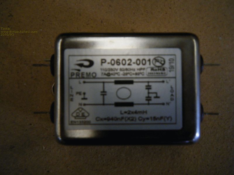
But they are only good for 7Amps so I would require 4 in parallel. What I did is reproduce the filter circuit with other salvaged parts: 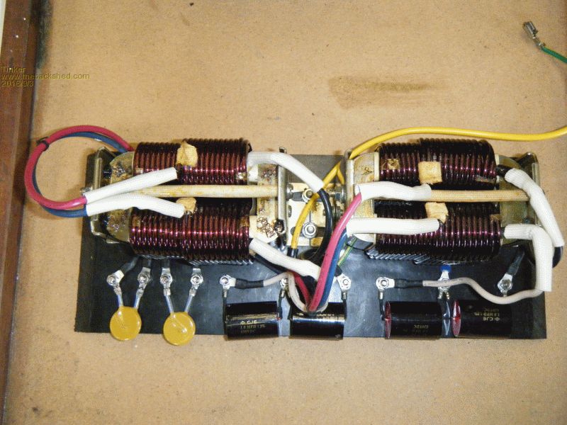
Since my double stack transformer was wound with 2 identical 230V secondaries I can connect one winding to each filter so the 2 chokes share the power between them. The 230V are paralleled after that, at the input to the Voltage & Current sensing board. I do not know yet how that filter will perform. The primary choke has now been wound, I beefed up the jig a lot to make that easier. 
There is a fair bit of hammering (soft face) involved to get that 4 in hand, 3 x 5 mm wire neatly wound on. It still bows out on the long side so the lot gets squashed a bit under my press after winding on all the turns. There are 2 ways to wind 4 in hand 3x5 wire, on its wider side or on its narrower side. Winding on the wider side is easy but there is only room for 3 turns on that plastic bobbin. Winding on the narrow side is much harder but gives 4 turns. I made one coil of each, the 3 turn coil to test the jig. This one is available, madness, if you still want it,send me a PM. I did some testing previously with 3 & 4 turn coils (tinkers inverter project) and found there is a reduction in idle current - but not a lot - with 4 turns. That was with the PJ electronics. I will test shortly how that 4 turn choke works with the EG002 board. Klaus |
||||
| Tinker Guru Joined: 07/11/2007 Location: AustraliaPosts: 1904 |
The home stretch is in sight, started testing today. First off was the primary choke coil, to see what thickness shims work best. Actually, no shim had the lowest standby current - 0.58A. But there was an annoying buzz from the choke. So I inserted the thinnest shim I had on hand, 0.06mm, which was from the mylar tape unwound from the donor toroid transformer. Most of that mylar tape is only 12mm wide but a little of it was 20mm which is ideal for the shims. 0.06mm shim had 0.59A standby current and the choke was silent. That is where I will leave it, I have now epoxied the coil in the plastic bobbin to stop it moving about. The idle current goes up with thicker shims. So the standby power used is 33W. This could be made lower if the secondary choke assembly were not used- those capacitors do draw some AC current. Just for comparison, with no primary choke fitted the standby power is 76W. A picture of the choke test set up: 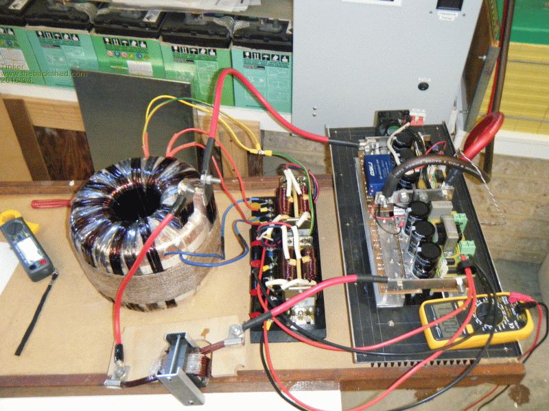
Next comes fitting everything into the enclosure, connecting it all up and then my inverter will be ready for power testing. Klaus |
||||
Madness Guru Joined: 08/10/2011 Location: AustraliaPosts: 2498 |
Hi Klaus, The filter you show in the tin box above I believe is from the DC input of the Aero-sharp, will they work as intended on AC? The one I am planning to use are in a larger box with 2 wires out each end. There are only 10 types of people in the world: those who understand binary, and those who don't. |
||||
oztules Guru Joined: 26/07/2007 Location: AustraliaPosts: 1686 |
Mad, they should do something, as the steel is less than paper thin, so they were designed with some frequency in mind from what I have seen I put one in the last unit I built, but have not tested it for noise so far. Klaus, good to see it finished and running. The 002 is a good little board, with surprising power characteristics.... still beware the over current.... I think I will make a comparator for the current sensing, and not use the current feedback pin, but instead direct the result from the comparator to the temp pin instead. I worry that the cfb pin can re-establish output if the signal is very short.... and this spells disaster for the torroid again. So the idea is to use any pulse that is over current for a set period of u/sec, and then push the comparator to drive the temp pin.. and hold for 1 sec before resetting, this should calm it all down a lot more..... maybe..... ..............oztules Village idiot...or... just another hack out of his depth |
||||
| Tinker Guru Joined: 07/11/2007 Location: AustraliaPosts: 1904 |
Its finished - I hope 
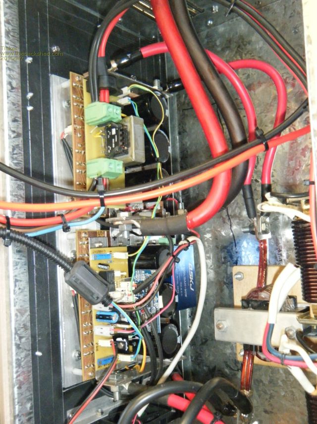
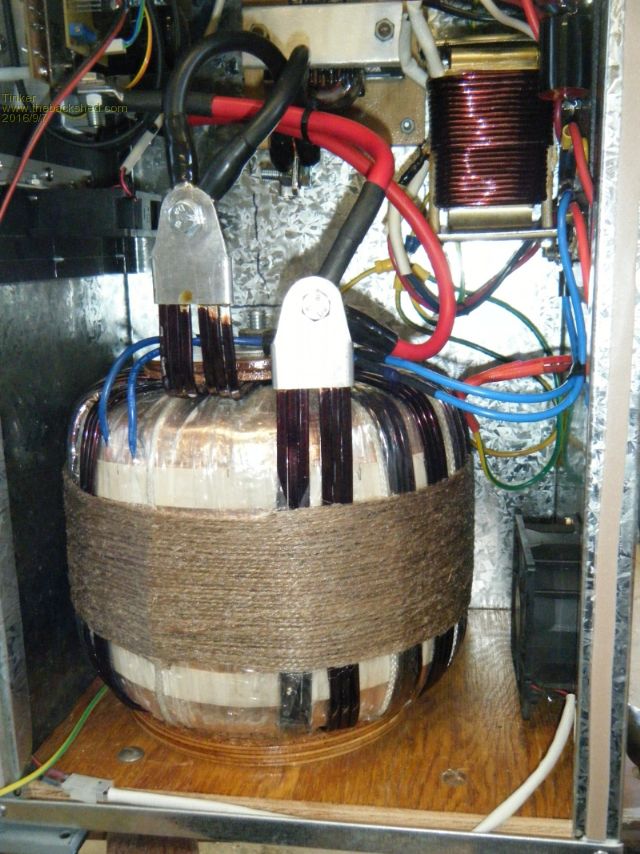
Everything fitted into my chosen enclosure and was relatively easy to wire up due there being sufficient room to get a hand or two inside. I used a galvanised toolbox for an enclosure. Its metal skin is quite thin unfortunately so heavy items had to be mounted on a sturdy backing. The thin sheet material did have the advantage of being able to use a nibbler to make the various cutouts. Also, this box was the right size and price  . .
So, here is what it looks like: 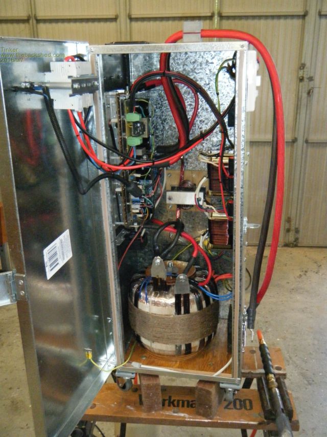
I had fitted a strong base to support the heavy toroid and decided to fit lockable casters as well. The latter were a good idea as my inverter now weighs 60kg, far to heavy to hang on a wall. The wheels let me move it to its final place, after I have finished load testing, with ease. I'm now waiting for a sunny day to see how it performs. Some more pictures: 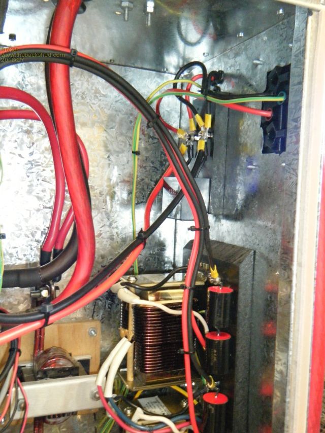
Klaus |
||||
| Tinker Guru Joined: 07/11/2007 Location: AustraliaPosts: 1904 |
oztules, could you elaborate on the above a bit please? Which signal is very short?? Thanks Klaus |
||||
oztules Guru Joined: 26/07/2007 Location: AustraliaPosts: 1686 |
The current sense pin is supposed to see a set period of usec's and then trigger, shut down for 16 seconds etc etc see data sheet. In practice I note that the current pull up seems to be able to stutter a bit if the signal is not solid, this leads to shunting/ false firing which leads to a failure, as it get confused and changes the frequency regime the transformer is used to...and well... it can get ugly from there. I would like to see any signal that matches the o/load I choose, to shut it down without any iff or maybe.... and then soft start from there... with or without a time lag of whatever we choose. As it is, I have seen it trigger, but then recover immediately and then trigger again.... and after a few of these events end on end, we pick up the pieces. If we miss a few cycles in there, then a recovery is really a hard start, which you would get away with in E I transformers with leakage, but not a heavy torroid. In truth, with the surge figures of the 4110 etc, if we had a less robust primary, we would probably be better off with no current trigger, and just rely on the o/loads. At least I have seen them drop out at 8kw and more with no harm done at all... I may try this too. On another thing, I tested the noise from the heavy wired filter you have there and I installed here in the latest one...... I think you will have to see what your looks like... mine did not block the hash from the front load washing machine.... so it coul never get the spin cycle initiated, as the noise was more than the feedback from the motor which the computer works out how much water has been drained from the clothes before the real spin. This is not a function of the inverter, but of noise.... ie the inverter will drive the load with consumate ease, but the washer computer gets confused feedback .....only at that part of the cycle, every where else in the wash cycle, it drives easily.... and it uses almost no power in that sense part of the cycle anyway. I then used the ferrite filters from the same aerosharp, and now it performs the spin sense part of the cycle perfectly well. So no as good as it looks, I don't think it is worthwhile as a noise suppressant. Yours is more sophisticated than my filter, but I think it will not work as planned for you. It never ceases to amaze me how little you learn when things work first up. Every time I have tested this type of inverter on the front load washer with phase trigger style motor it has not failed at all..... but I never realised that the boss does the washing in the morning... ALWAYS when coincidentally the hot water is heating, and using 2.5kw... and suppressing the noise with the dead load... so this noise problem never surfaced until today.... always learning.... 
...........oztules Village idiot...or... just another hack out of his depth |
||||