
|

|
Forum Index : Windmills : Requesting selecting wire size for stator
| Author | Message | ||||
| govertical Guru Joined: 11/12/2008 Location: United StatesPosts: 383 |
Hi, the total ratio is 7: 1, the blade rotor spins one time and the magnet rotor spins seven times. Thanks for the advice regarding the pulley size. I am happy with the PMA design. I have to fabricate new stators to increase the output for the size magnets that I am using. I did find a bearing that I can use to solve the biggest problem of the shaft being pulled off center. It will be a few days to fabricate the housing. Thanks again and enjoy the day. 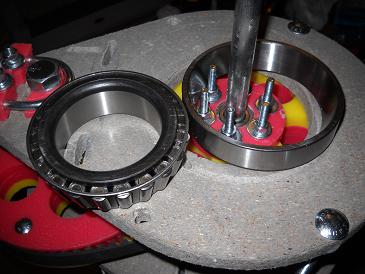
just because your a GURU or forum administer does not mean your always correct :) |
||||
| govertical Guru Joined: 11/12/2008 Location: United StatesPosts: 383 |
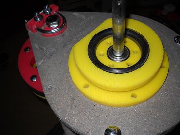
photos of bearing mount 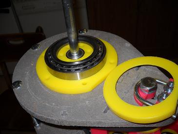
just because your a GURU or forum administer does not mean your always correct :) |
||||
| Rastus Guru Joined: 29/10/2010 Location: AustraliaPosts: 301 |
Hi Go Vertical, Your diagnostic skills must be improving.You're giving them a workout.Keep at it.Cheers Rastus see Rastus graduate advise generously |
||||
| govertical Guru Joined: 11/12/2008 Location: United StatesPosts: 383 |
Hi, I believe the shaft being pulled off center is the reason earlier attempts failed. I hope this solves the problem and is worth the extra time and expense. Enjoy the day. just because your a GURU or forum administer does not mean your always correct :) |
||||
| yahoo2 Guru Joined: 05/04/2011 Location: AustraliaPosts: 1166 |
I was hoping you just had that tapered roller laying around and didn't buy it. I can see that it is a convenient quick fix to prove a concept on a prototype because the inside diameter fits the hub on the generator shaft. there are some major drawbacks in using tapered roller bearings in wind turbines that can result in high failure rates. Poor preloading technique is very common. When the time comes for a working version, spherical bearings with lock collars and pressed steel or cast housings are the most practical, cheap and tough option. 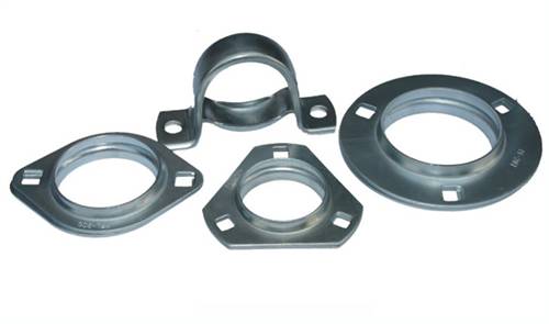 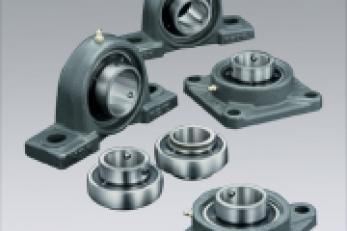
I would encourage you to have a play with some so you can see the potential, they are a joy to work with. yahoo I'm confused, no wait... maybe I'm not... |
||||
| govertical Guru Joined: 11/12/2008 Location: United StatesPosts: 383 |
Hi, the bearing was the only one I could find that was large enough. There is no real preload, the race fitís the bottom mount, the roller bearing just sit on top with a grease cap and the blade rotor holds it all together. I have the bearing mounted and manual inspection shows improvement. Road test in the near future. I will continue to search for a better solution. Thanks for the info, enjoy the day. just because your a GURU or forum administer does not mean your always correct :) |
||||
| govertical Guru Joined: 11/12/2008 Location: United StatesPosts: 383 |
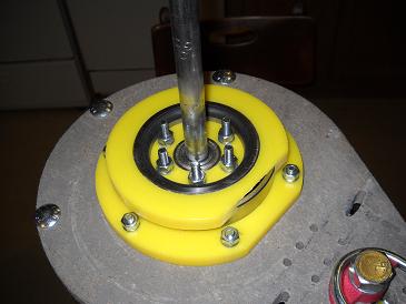
Hi, the blade rotors are mounted using bearing and transfer energy to the belt drive using the bolt ends extending upward located near the center. Using a lager ID bearing as shown is the only solution that I could think of that will still work with what is there. photo of completed assembly 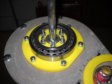
just because your a GURU or forum administer does not mean your always correct :) |
||||
| govertical Guru Joined: 11/12/2008 Location: United StatesPosts: 383 |
Hi, results of todayís road: MPH_____DC Amps_______using 12 volt deep cell as test load 10_______0.15 15_______0.5 20_______1.0 25_______3.0 30_______4.0 35_______5.0 The added top bearing made all the difference. The belt did not skip. I tighten the belt and ran the test again and the added bearing load greatly reduced the output. I have to find the ideal belt tension. Todayís test also showed the that belt drive ratio is to high for the blade size and design being used and was creating a stall condition. Comments welcome just because your a GURU or forum administer does not mean your always correct :) |
||||
| govertical Guru Joined: 11/12/2008 Location: United StatesPosts: 383 |
Hi, I am comparing the data from todayís test with the results from the data posted with the 3:1 gear drive. The results were almost the same until the wind speed reached 30 MPH. Than the blades started to stall. It appears that doubling gear ratio just increased the load and did not increase the output. I wonder if this is always the cast? Comments welcome http://fieldlines.com/board/index.php/topic,143852.342.html just because your a GURU or forum administer does not mean your always correct :) |
||||
| Rastus Guru Joined: 29/10/2010 Location: AustraliaPosts: 301 |
Hi Go Vertical, I'm curious,how are you measuring the wind speed?Cheers Rastus see Rastus graduate advise generously |
||||
| govertical Guru Joined: 11/12/2008 Location: United StatesPosts: 383 |
3:1 test results http://fieldlines.com/board/index.php/topic,143852.342.html 7:1 test results http://fieldlines.com/board/index.php/topic,143852.msg997850 .html#new Hi, I used a hand held anemometer and the gauge on the dash board. One time I mounted the VAWT in the back of a truck and used the hand held anemometer. I was riding in the back during the test and the measure wind speed was the same as the MPH reading on the dash board of the truck. Because I increased the geared ratio of the transmission on the VAWT, I was expecting to see a increased output at lower wind speeds but they were about the same. I am puzzled by the compared test results. 3:1 test results 7:1 test results just because your a GURU or forum administer does not mean your always correct :) |
||||
| Rastus Guru Joined: 29/10/2010 Location: AustraliaPosts: 301 |
Hi Go Vertical, I must be miss reading the results!It appears to have a good percentage increase in the lower speed range.It may be less than what you where exspecting though.Cheers Rastus see Rastus graduate advise generously |
||||
| govertical Guru Joined: 11/12/2008 Location: United StatesPosts: 383 |
Hi, I more than double the geared ratio, I was expecting to see a increase in the output at the lower wind speed. The outputs are basically the same until 30 MPH. I do not understand why. Before I start making changes to the PMA, I want to have the mechanics working as well as possible. The only thing I think of is the geared ratio is to high and the added load of the transmission combine with the PMA load has produced the same numbers. The output results above 30 MPH are different, indicating the geared ratio is to high for the size blades I am testing with. I do not understand why the output did not improve at the lower wind speeds. Comments welcome just because your a GURU or forum administer does not mean your always correct :) |
||||
MrDelanco Senior Member Joined: 12/11/2011 Location: United StatesPosts: 101 |
What are the output readings? Volts? amps? watts? MrDelanco:Project Videos It is not only too know what it does but to understand how it does what it does. |
||||
| govertical Guru Joined: 11/12/2008 Location: United StatesPosts: 383 |
Hi, all the measurements are DC amps using a 12 volt deep cell as a load. I do this because the value of Watts can be misleading. Is it 10v x 1 amp or 1v x 10 amp. just because your a GURU or forum administer does not mean your always correct :) |
||||
| Tinker Guru Joined: 07/11/2007 Location: AustraliaPosts: 1904 |
10 x 1 or1 x 10 leads to the same result - 10 Watts in this case  Klaus |
||||
MrDelanco Senior Member Joined: 12/11/2011 Location: United StatesPosts: 101 |
Check each pma separately, you may have the stack wired incorrect, where one is fighting the other. MrDelanco:Project Videos It is not only too know what it does but to understand how it does what it does. |
||||
| govertical Guru Joined: 11/12/2008 Location: United StatesPosts: 383 |
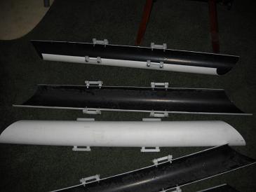
Hi, a earlier test showed a higher amp output. My blades are to small and the geared ratio is to high. I have completed the new blade assemblies and hope to road test soon. Thanks for the suggestion. Enjoy the day. 
just because your a GURU or forum administer does not mean your always correct :) |
||||
| govertical Guru Joined: 11/12/2008 Location: United StatesPosts: 383 |
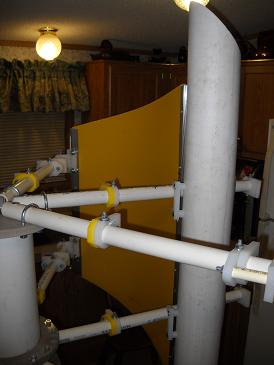
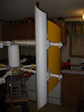
The core structure allows the scoop to be positioned as Lenz, C rotor, or internal J style. new blade photos 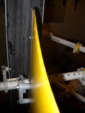
just because your a GURU or forum administer does not mean your always correct :) |
||||
| Rastus Guru Joined: 29/10/2010 Location: AustraliaPosts: 301 |
Hi Go Vertical, Have you matched the new blades to the present ratio,or reduced the step up ratio as well.Cheers Rastus see Rastus graduate advise generously |
||||