|

|
Forum Index : Electronics : Stock Std Warpinverter
| Author | Message | ||||
renewableMark Guru Joined: 09/12/2017 Location: AustraliaPosts: 1678 |
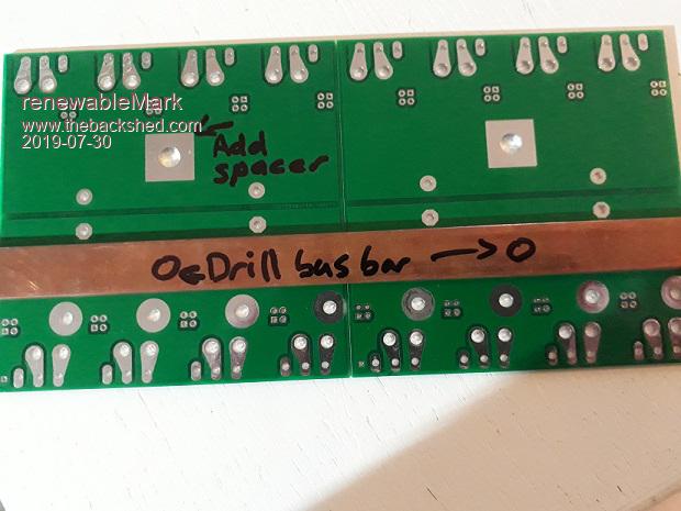
Thanks mate, I was planning to solder it, so if an area 16mm or so left blank that would save me scratching it off. Probably don't need to bolt it down, that amount of solder should give a good mount, but maybe a bolt hole at each side will prevent the surface lifting from the board. Cheers Caveman Mark Off grid eastern Melb |
||||
mackoffgrid Guru Joined: 13/03/2017 Location: AustraliaPosts: 460 |
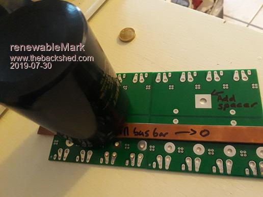
All of this is no problem.  Have you thought about bolting the buss under the capacitor so when you bolt the capacitor on it also connects to the buss bar? The positive side cold also be bussed all just spaced out. The private messages are off-line so I might ask Tony or Gizmo to provide each other with email addresses so I can send you images, gerbers etc while we work this out. Cheers Andrew |
||||
renewableMark Guru Joined: 09/12/2017 Location: AustraliaPosts: 1678 |
That's a ripper idea!! WTF didn't I think of that   I could just use the boards I have now then.  Cheers Caveman Mark Off grid eastern Melb |
||||
mackoffgrid Guru Joined: 13/03/2017 Location: AustraliaPosts: 460 |
  |
||||
renewableMark Guru Joined: 09/12/2017 Location: AustraliaPosts: 1678 |
What a simple fix.... ripper!  Just need to strip back the solder mask a bit. Cheers Caveman Mark Off grid eastern Melb |
||||
mackoffgrid Guru Joined: 13/03/2017 Location: AustraliaPosts: 460 |
Mark, it's not a "fix" it's a cleverly engineered feature   |
||||
| Warpspeed Guru Joined: 09/08/2007 Location: AustraliaPosts: 4406 |
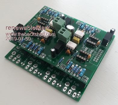
The busbars will also greatly stiffen the whole circuit board assembly to carry the weight of the capacitors and tie everything together mechanically. Its then possible to put together a really physically large inverter, using "thin" standard 1.6mm board material, and standard one ounce copper layers. A further advantage is that it all comes apart very easily if ever anything needs to be replaced. Its difficult enough soldering really heavy parts in place, its a lot more difficult unsoldering things without making an unholy mess. And it looks nice  Cheers, Tony. |
||||
| BenandAmber Guru Joined: 16/02/2019 Location: United StatesPosts: 961 |
That looks a little bit like one of your builds warp speed with the single giant capacitor on the little board I really like that bus bar idea be warned i am good parrot but Dumber than a box of rocks |
||||
renewableMark Guru Joined: 09/12/2017 Location: AustraliaPosts: 1678 |
I only have lengths of 250mm long, just wondering whether to scarf cut and solder. Found http://www.georgewhite.com.au/ 3.2x19mm $21+gst per metre..... ripper, just buy a length. Cheers Caveman Mark Off grid eastern Melb |
||||
| Warpspeed Guru Joined: 09/08/2007 Location: AustraliaPosts: 4406 |
I would just use aluminium to begin with. Its cheaper and much easier to work with and Bunnings have a good range in various lengths. Pretty easy to later on replace with copper from George White when happy with how it all goes together and works. Use the original aluminium busbars as a drill guide for the copper. https://www.bunnings.com.au/search/products?q=aluminium%20flat%20bar&redirectFrom=Any Cheers, Tony. |
||||
renewableMark Guru Joined: 09/12/2017 Location: AustraliaPosts: 1678 |
I have a job close to there tomorrow so may as well pick up a metre or two. I don't have a good track record of upgrading temporary fittings, once it's working it gets left that way, so I'd rather do it properly from the start. Caps were $300, gone to an effort winding the torroids, may as well do the rest properly. Little dc/dc supplies came today, just need the IDC connectors and the 4420 chips(where applicable).  Cheers Caveman Mark Off grid eastern Melb |
||||
mackoffgrid Guru Joined: 13/03/2017 Location: AustraliaPosts: 460 |
$300 for caps, <whistle> It'll be double of what I'll be paying for a single 100v unit - I think, but if it achieves your goal it's cheap. If I remember your caps double the ripple current capacity per bridge board. As with the Oz inverter I'd recommend taking the caps off for your first power up test. Cheers Andrew |
||||
renewableMark Guru Joined: 09/12/2017 Location: AustraliaPosts: 1678 |
Take the caps off to test? Ahhhh what could go wrong? Reminds me of this.  Yeah, those 4 caps were almost $300, so the entire build hmmm dunno, 3kw torroids were between $75 and $100 each depending on where I got them, the smaller ones for toroids 2,3&4 were cheaper. Primary cables, around $200. Boards, components $100-$150 Filters, heavy DC cables, breakers etc. Would probably be over $1000 when it's all done, but for a very capable unit that is still very good value. Cheers Caveman Mark Off grid eastern Melb |
||||
| Warpspeed Guru Joined: 09/08/2007 Location: AustraliaPosts: 4406 |
Should run safely without any caps there Mark. There may (?) be a lot of crap on the dc supply without the caps, which means there will also be the same crap on your sine wave. But its a safer way to apply limited power through a resistor for a very first initial power up. The dc input voltage measurement on the control board my also become very confused if the dc supply is really jumping around. So without caps fitted, the whole thing will run, but it may not look very nice and may go a bit spastic. But its not destructive. Start with just the largest inverter running, then progressively add each next lower inverter. Cheers, Tony. |
||||
renewableMark Guru Joined: 09/12/2017 Location: AustraliaPosts: 1678 |
With no caps what would make the DC go spaz if there is no load on it? Cheers Caveman Mark Off grid eastern Melb |
||||
| BenandAmber Guru Joined: 16/02/2019 Location: United StatesPosts: 961 |
If you've ever grown a tomato plant or to the tomatos off those plants taste so much better than the store and it doesn't really matter if you have twice as much money in them Well with these inverters you have something way better then store brought and it's not just in your mind and they're cheaper and you know how to fix them if they break down So that looks like a win-win all the way around to me be warned i am good parrot but Dumber than a box of rocks |
||||
| Warpspeed Guru Joined: 09/08/2007 Location: AustraliaPosts: 4406 |
The way this type of inverter works, the outputs of four inverters are combined. To build up a sine wave shape, some inverters work in opposition to other inverters at different points on the waveform, so power is constantly shuffling back and forth through each inverter. Each inverter being completely bi-directional as far as power flow. If the voltage supply is "soft" that may possibly cause some switching spikes to appear on the dc supply and the output waveform. Its going to be much worse of course with any applied load. None of this may actually happen, but I just wish to prepare you for a possible situation that without any caps fitted there may be a lot of garbage on the waveform. Or much more likely it will all work very well, until you place a load on it. Its not going to blow up ! But the waveforms may be less than text book perfect without caps. Cheers, Tony. |
||||
mackoffgrid Guru Joined: 13/03/2017 Location: AustraliaPosts: 460 |
Mark, I assume I'm error prone, which I am. The design is quite tolerant but my capacity to make silly dumb mistakes is high. So, in testing; Caps & Transformer Off - Ensure all driver boards are installed, even if they are not being driven. - I'd leave the caps and transformers OFF initially. - Use a resistive supply to the DC rail. Two, in series, of those 20W 30R resistors off the AeroSharp boards should do. - Use a 10k load instead of the transformer primary. - Test each inverter (bridge) one at a time, by using the drive signal for the big transfomer - using your little scope across the 10k load you should see a 50Hz positive cycle and negative cycle. This will test the basic functionality of the Mosfet driver circuitry including the little power supplies etc, as well as the bridge itself. You'd be hard pressed to release much smoke with this setup. Caps off - Transformers Next - Keep the resistive supply on. - Progressively connect - add a transformer. Correct polarity as you go. Caps on - install the caps, use a charging resistor, and start loading her up. |
||||
mackoffgrid Guru Joined: 13/03/2017 Location: AustraliaPosts: 460 |
If you don't want to run the tests without capacitors, an alternative is to supply the DC rail with only say 4v using a CCCV (constant current, constant voltage) as in the LM2596 module (with CCCV option). At this low voltage the Caps don't seem to have the energy to blow the Mosfets. Cheers Andrew |
||||
renewableMark Guru Joined: 09/12/2017 Location: AustraliaPosts: 1678 |
Thanks guys, yeah it will be easy to test without caps, that's how I did the Madinverter. At least with the bolt on ones it's easy to do. Cheers Caveman Mark Off grid eastern Melb |
||||