|

|
Forum Index : Electronics : Micro controller driven Warpverter
| Author | Message | ||||
| Warpspeed Guru Joined: 09/08/2007 Location: AustraliaPosts: 4406 |
Just went out to the shed and tried a few of these supplies. Some struggled to start at 40v under no load, so you are quite right. There is going to be a problem at 48v. Probably the easiest and least painful fix for this, might be to boost the battery voltage up to say +60v with one central switching power supply, and run all the little guys off that. Something like this perhaps: https://www.ebay.com.au/itm/DC10-60V-600W-10A-Converter-Step-up-Boost-Constant-Current-Power-Supply-Driver/253979818362? ssPageName=STRK%3AMEBIDX%3AIT&_trksid=p2060353.m1438.l2649 Cheers, Tony. |
||||
renewableMark Guru Joined: 09/12/2017 Location: AustraliaPosts: 1678 |
Tony, just checked what is left, I gave a few of the 1500's away the other day, only have one left, but plenty of 2kw's. I can try and hunt down some more if needed, but the 2kw should be fine shouldn't it. Still have a 1500 for No4 toroid. Cheers Caveman Mark Off grid eastern Melb |
||||
| Warpspeed Guru Joined: 09/08/2007 Location: AustraliaPosts: 4406 |
Mark, Why not use the 1500 for number three, its still going to be twice the size it needs to be. Number four only needs to be 250 watts and I have a 400 watt bare core you can have for that. Can you give me some dimensions for that 1500, and I will see how that works out. Cheers, Tony. |
||||
| Tinker Guru Joined: 07/11/2007 Location: AustraliaPosts: 1904 |
Excellent idea Tony, it so happens that I use something similar to boost my bench power supply voltage to test things. Already ordered one of the above now  . .Now I only have the output voltage problem left..... Klaus |
||||
| Warpspeed Guru Joined: 09/08/2007 Location: AustraliaPosts: 4406 |
If you order a bunch of 12v 400mA supplies, and tweak the voltage up just a bit, that should do very nicely. Cheers, Tony. |
||||
renewableMark Guru Joined: 09/12/2017 Location: AustraliaPosts: 1678 |
OK I'll strip the 1500. Cheers Caveman Mark Off grid eastern Melb |
||||
| Warpspeed Guru Joined: 09/08/2007 Location: AustraliaPosts: 4406 |
Just thinking about number four. Do you have any 1.4mm diameter wire ? Cheers, Tony. |
||||
renewableMark Guru Joined: 09/12/2017 Location: AustraliaPosts: 1678 |
Nup, everything I have is all aerosharp stuff. That's all 1.6mm, I can buy other stuff if it's a better plan. No hurry now, the only thing that pi$$ed my inverter off was the air con, and now summer is over that isn't an issue. Cheers Caveman Mark Off grid eastern Melb |
||||
| wiseguy Guru Joined: 21/06/2018 Location: AustraliaPosts: 1156 |
Klaus Here is the datasheet I linked to 2019-04-10_235610_THX208-TongHuaXin.pdf A photo or two could help to identify the configuration. There is a resistor in the schematic (P11) R2 which is a 2.2Meg start-up resistor - change it to 220K - 1Meg and check the start up voltage. The capacitor will make bugger all difference in this application but changing it to 47u @ 63V wont hurt at all. Tony is right about the auxiliary or bootstrap voltage fed from D3 into C6. Carefully measure the voltage across C6 when a unit is running and note it. Cutting back the auxiliary voltage after increasing the main output voltage can be done if needed by adding a couple of resistors, if we are reducing the main output to a lower level the auxiliary may get too low to run properly and a resistor and zener added to the ground leg of the auxiliary winding can raise the auxiliary back up to solve that. It is a bit of mucking about - but if you already have some units you want to use there are options. The data sheet also says: l 低输出降频功能,无输出功耗可低 于0.25W I think that means a minimum load of .25W is required (1K @ 15V). My suggestion if you have to buy more is also to buy 12V units and raise them to around 14 - 15V to minimise issues, reducing the startup resistor R2 as above should also help it to start up at a lower voltage. If at first you dont succeed, I suggest you avoid sky diving.... Cheers Mike |
||||
| Tinker Guru Joined: 07/11/2007 Location: AustraliaPosts: 1904 |
Thanks for that Mike, you are full of surprises. I had no idea you can read Chinese characters  . .I will play around with that start up resistor just to see what happens. But I'm now committed to using the smaller modules (you posted a link for them a while ago) as they will fit on my PCB much easier. These will be 12V units BTW. Tony's idea of overcoming the startup issue by using a 60V supply for the modules makes a lot of sense and I will use that also. It may be OK to do extensive mods to one module but that fun soon fades when 16 modules are used. Especially if it involves mucking around SMD parts. These modules are cheap enough so filling up my odd parts box with the 24V versions I had ordered before is no hardship. Klaus |
||||
| LadyN Guru Joined: 26/01/2019 Location: United StatesPosts: 408 |
Let me know if discussions about these little modules should be moved to a seaprate post so it's easy to track and decouple from this topic. For now I have two questions: 1. If the switching IC is powered off the isolated secondary winding of the little transformer, what gets the transformer initially running or the IC powered when there's only DC/no power to the primary? 2. Except for the startup circuit, should not rewinding the little transformer help get it running at lower than nominal voltage? For example, instead of 100v nominal, we can now get it to start (and be stable) at 48v nominal? I am learning a lot, so thank you! |
||||
| Warpspeed Guru Joined: 09/08/2007 Location: AustraliaPosts: 4406 |
What happens Natasha is that there is a high value startup resistor that very slowly charges an electrolytic. As the voltage rises across the electrolytic, at some point the control chip bursts into life and starts working. Once the supply is running it is powered from an auxiliary winding on the transformer. If that auxiliary supply is insufficient, the chip shuts down from undervoltage, and the startup process begins again. It will then pulse on and off trying to start up, but it cannot quite make it. With a bit higher input voltage the chip will start up and be sustained by power from the auxiliary winding. If we start messing with the resistors in the feedback to change the regulated dc output voltage, that also changes the voltage on the auxiliary winding and we might be in trouble. Moving it up or down by say twenty percent will probably be fine. Going down to half, or up to double with the auxiliary voltage might be inviting trouble. Cheers, Tony. |
||||
| LadyN Guru Joined: 26/01/2019 Location: United StatesPosts: 408 |
OK, so there might be two changes we need to do to support a lower input voltage: 1. Change both the R, C values so it supports the lower input voltage. 2. Change the windings to account for the lower input voltage. I am assuming the voltage required for the control IC is lower than the input voltage (which is why this capacitative dropper is used to bootstrap the circuit)? I don't understand flyback supplies yet so my understanding is likely very basic and incorrect, so I really appreciate the details Tony! |
||||
renewableMark Guru Joined: 09/12/2017 Location: AustraliaPosts: 1678 |
Wiseguy, google translate converted it to "Low output down-conversion, no output power can be less than 0.25W" Cheers Caveman Mark Off grid eastern Melb |
||||
| Warpspeed Guru Joined: 09/08/2007 Location: AustraliaPosts: 4406 |
I have actually looked into both those very logical suggestions previously. Changing the RC vales will enable the chip to start up, but the power produced is so meager it cannot self sustain, so it is not really a solution. The transformers are dipped in something that is then oven baked and goes as hard as a rock. The ferrite core halves just cannot be separated without breaking them. Its all just hopelessly impractical. Best solution is to get the very common 12v supplies and tweak the output voltage up very slightly to 13v to 15v. That works, and with luck its just changing one resistor. Cheers, Tony. |
||||
| LadyN Guru Joined: 26/01/2019 Location: United StatesPosts: 408 |
Thank you Tony! I had an order for 6 of these placed just yesterday so it'll be a few weeks before I get my hands on them but do you think boiling them in water might help unwind them? I am referring to this video: https://youtu.be/IOwT8GkvIjs?t=35 Do you think it might be applicable in this case? of course, without the startup voltage, it might make this a non starter The reason for all this reflection is to get these to start at lower voltages like 48 or 72V without needing a boost convertor. Less moving parts, less things to go wrong, specially these unknown, irreparable convertors with fake parts all over. |
||||
| Warpspeed Guru Joined: 09/08/2007 Location: AustraliaPosts: 4406 |
It depends... If its epoxy based goo just holding the ferrite parts together, it will very likely soften in boiling water. Most epoxies go soft above around 80C. Professional transformer lacquers are very low viscosity to soak right into, and between all the turns by capillary action. That is the whole idea to keep the air and humidity out. Its more like the clear estapol coating often used to coat bare wooden floorboards. Its as hard as Hell and nothing is going to shift it once it has fully cured. Its also made to work at constant 200C+ temperatures, the same as the insulation on the copper wire. The transformer in the video is match box sized, these are much smaller at around a 15mm cube size. The wire on the primary is about human hair thickness with a very large number of turns to work up to 400v dc input. Its the primary we need to reduce the turns on, but unfortunately that is the inner most winding. Its really just not a practical proposition to modify sixteen of these. The battery voltage booster is only required to produce about five watts to run just the little supply boards, not the whole inverter ! So its going to be small, low cost, simple to do and potentially trouble free. Cheers, Tony. |
||||
| Mulver Senior Member Joined: 27/02/2017 Location: AustraliaPosts: 160 |
Hey Mark, Hows the winding going? |
||||
renewableMark Guru Joined: 09/12/2017 Location: AustraliaPosts: 1678 |
Whoops, replied in the wrong thread, answered here Cheers Caveman Mark Off grid eastern Melb |
||||
| poida Guru Joined: 02/02/2017 Location: AustraliaPosts: 1419 |
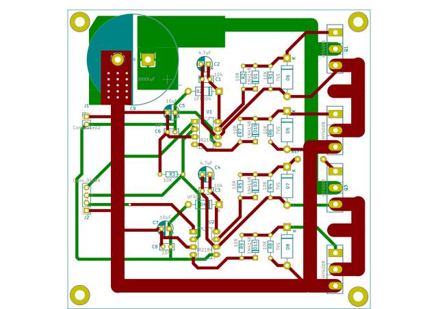
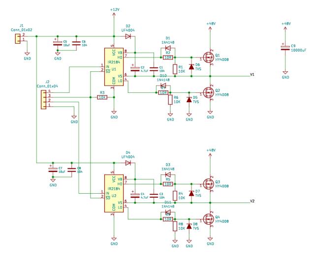
I've just completed, with errors yet to be identified, the power board I will be using in my test Warpverter. I need 4 of these:   Only need one 12V supply for the drivers. The need for 18 isolated supplies and more is not going to happen if I'm doing it. wronger than a phone book full of wrong phone numbers |
||||