
|

|
Forum Index : Windmills : My unorthodox Build
| Author | Message | ||||
| BarkyJ Senior Member Joined: 26/04/2018 Location: New ZealandPosts: 114 |
Fair point Madness. That said, my windmill is without a tail, so it won't be turning in circles, and will just vary in power instead I guess. Time will tell how well it works. Cheers |
||||
Madness Guru Joined: 08/10/2011 Location: AustraliaPosts: 2498 |
I had thought of damping or motorizing it to stop the 360's. For a wind generator to work properly the wind needs to hit the blades dead straight, anything else and your blade geometry is incorrect. There are only 10 types of people in the world: those who understand binary, and those who don't. |
||||
| BarkyJ Senior Member Joined: 26/04/2018 Location: New ZealandPosts: 114 |
Time for a bit of an update. Hi All :) So, the motor for the Turret movement is installed, 9 tooth gear on the motor, 44 tooth sprocket on the base of the turret. 300 RPM motor, PWM'ed for a slower speed. I have a gear tooth sensor which I am using as a home sensor, and I ended up going with the Encoder option, so have a quadrature encoder which outputs 2400 pulses per revolution, so overkill but working really well. Have the controller just talking to everything today for the motor with some test logic, so I can manually adjust the position of the turret and move to specific positions based on the encoder output. Works great, but more stuff to add in there yet. Before I installed it all on the mast, I bolted the motor and encoder and a dummy sprocket together and had the motor moving the sprocket to a set position based on the current wind direction. So if I move the sprocket with my hand, the motor would periodically return it back to the current direction of the wind, based on my wind sensor. That all worked really well and enabled me to get the logic right for that part. So in practice on the turret, it will do a similar thing. The encoder will keep track of the position, so if it does move a little with the wind or overshoots in movement etc, then it will correct itself periodically. I have Auto and Manual modes on the controller, so in Auto it will follow the wind, and in Manual I can move it wherever I want. I am planning to be able to apply offsets if required, so I can play around with the heading and see how the power output changes. Stuff for me to learn with essentially. I will be able to turn it out of the wind if the wind gets too strong, or offset it from the wind a bit etc, should be rather neat. I can also turn it into the park position, so I can lower the mast and put it in the maintenance position (where it is in the video below) so the blades are facing the sky. 1 man job to raise and lower it already, worked out really well. All the cables are inside the pole now, then coming out of the bottom into a conduit and running to the shed. I have 2x 3 core mains extension leads for the main generated power. Since I will be generating a wide voltage output, the current is low, so normal mains extension leads are a cheap solution - thanks Bunnings. I then have a 4 core cable going up there also, which I am currently using 3 cores for, for the RPM sensor. I then have the 2 core motor power cable which comes out below the turret, along with a 6 core cable for the Encoder and Home sensor, with 1 core spare. Plenty of cable in the mast. I opted not to use the slip rings in the end. After I received it I was not that happy with the size of the wiring, even though it stated it was good for 5A per channel. Decided against using it, and will just keep track of turret rotations and if I get a twist going on, I'll just have it automatically unwind itself when there is no wind (or something to that effect). So the main controller for this is in the shed about 20m of cable away from the windmill. I then have the controller wirelessly sending information to the house, and I have an LCD in my office so I can monitor everything that is going on. Got that all working and things seem stable. Lots more to add, but the base functionality is there. Blade wise, I got the blades bolted to the hub with their support braces, and I am pretty happy with how it all turned out. As a starting point, I just set the angle of attack to be the default where the blades wanted to sit, and I will experiment from there, by changing the angle by spacing out the leading edge. Once I have something I am happy with, ill smooth out the brackets a bit and possibly even fill things in, but this is a start just to see where we are at. I also balanced the blades by drilling a hole through the centre of a bolt, and hanging the whole assembly from the ceiling of the garage, having it hang about 100mm above the ground. I then put weights on blades and got it all sitting level. I was going to put a weight near the tip, but at this stage, I have put a large fishing lead on the hub itself. Looks ugly, but until I get things a bit more finalised, this works well, and things seem happy enough to try. So, end of next week, I hope to have the motor logic finished off, and Auto mode fully tested and following the wind. I plan to put a stick on top of the rotors so its clear which way its pointing, and then monitor it based on the wind vane (or the average data from the wind vane at least) and just make sure its tracking correctly. Then when that is proven, I will put the blades on for a test run, and see what happens. gulp. I have a long list of things still to do, test and complete. Loving this project, learning a lot and not expecting to get things right first go, but giving it a good crack. Here are some pictures, and 2 video clips from a week or so ago just of the blades free spinning on a washing machine drum, as a test after balancing it, and then a video from today after I got the motor logic installed, and tested it while my son was up the hill with the camera. Video 1 Video 2 Video 3 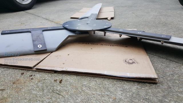 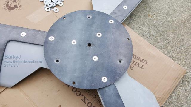 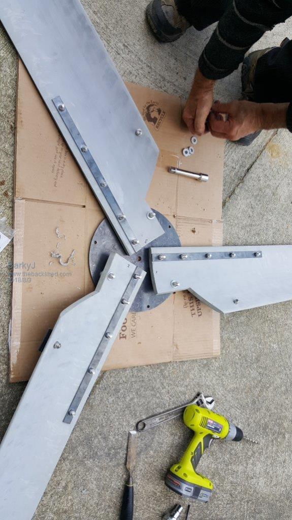 3D printed some solid brackets for the encoder and the Home sensor. 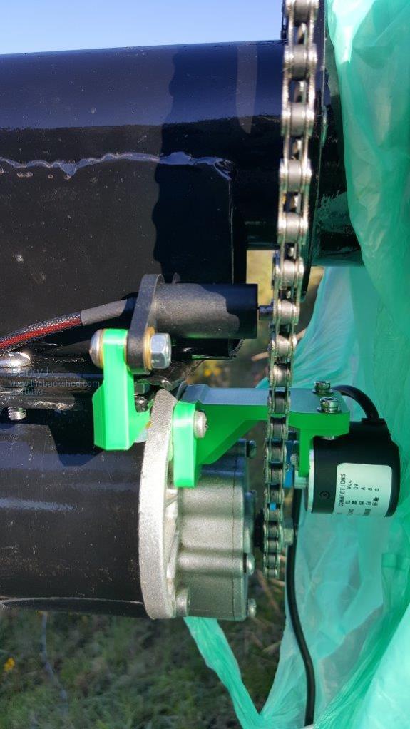 Not a huge amount of wind, but its fairly constant. Had a few days with basically nothing at all, but this is workable I think. 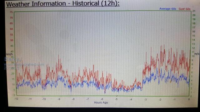 The cover will go on next week to keep most of the water out of here, and I will make something up to cover the motor and sprocket too, to keep most of the water off them. 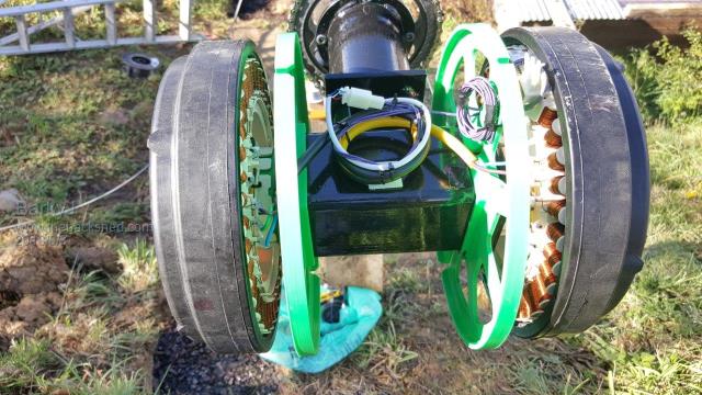 Fun and games and making progress. I likely could have almost had a test this weekend, but I am away for the weekend so next week it is. Cheers James |
||||
| flc1 Senior Member Joined: 20/11/2011 Location: New ZealandPosts: 242 |
Gday James. I havn't been on this site for a while, just having a quick look,its a nice looking build you have here,,, don't mean to put a dampner on things but after looking at your hub I have a concern that it is not going to be strong enough, too thin, not enough strength for that diameter blades,in high winds/rpm the blades are trying to move clockwise/anticlockwise,twisting/flexing forwards and backwards,,really doing there best to ripp themselves off the hub,and if the hubs too thin they will take a part of that with them when they leave.. I would double up the stengthening of the whole hub and blade mount strutes ,If you don't then I would stay well away from it in high winds,,but thats just my opinion. |
||||
| Boppa Guru Joined: 08/11/2016 Location: AustraliaPosts: 814 |
I tend to think it might be a bit light too- what thickness is it?? the Delco's had a 3/16 thick plate hub and they often bent the hub (thats 5mm near enough) with 75cm blades |
||||
| BarkyJ Senior Member Joined: 26/04/2018 Location: New ZealandPosts: 114 |
Really? The plate in the picture is 1 of 2, both are 6mm thick and bolt together, the arms going out are also 6mm thick. The backing bracket on the other side of the blades are just 3mm thick but are basically just a glorified washer, and the blades are 16mm thick. |
||||
Madness Guru Joined: 08/10/2011 Location: AustraliaPosts: 2498 |
Is it possible to put another round plate on the other side, that would give it a lot more strength? Those 3D printed parts look good, makes me think I need a printer. There are only 10 types of people in the world: those who understand binary, and those who don't. |
||||
| Tinker Guru Joined: 07/11/2007 Location: AustraliaPosts: 1904 |
As an armchair observer  I too would suggest putting another disk on the windward side, perhaps similar than the rear disk plus similar steel brackets. So you end up having the blade sandwiched between equal strength brackets. I too would suggest putting another disk on the windward side, perhaps similar than the rear disk plus similar steel brackets. So you end up having the blade sandwiched between equal strength brackets.Also, turn the screws around so the smooth countersunk bit faces the wind. Never under estimate the centrifugal force on your balancing weights, they *must not* move under any circumstances. Do make a very good weather cover, with shaft seals etc unless you like to do a lot of maintenance. Something the birds do not like to sit on on windless days too. Klaus |
||||
| BarkyJ Senior Member Joined: 26/04/2018 Location: New ZealandPosts: 114 |
The bolts are countersunk as the heads are between the two plates. There is another plate the same size as the one pictured which bolts to this one, and is what joins it to the generator. The main generator shaft goes through both plates also. I am likely to put a smaller plate on the windward side but I haven't got to that yet. Cover wise, the shafts are fully enclosed. The cover I have made covers most of the rotors too. Only the ends stick out. |
||||
| dwyer Guru Joined: 19/09/2005 Location: AustraliaPosts: 574 |
Hi Member everyone seem to worried about the thickness of the mild steel plate and its strength that barky is using on his project, so 6 mm steel place should be ok but if it was for i would better go for 4-5mm bisalloy 400 or 350 grade steel plate as they are much stronger and better for drilling holes which would need good quality drills bits as well  dwyer the bushman |
||||
fillm Guru Joined: 10/02/2007 Location: AustraliaPosts: 730 |
IMO" & sorry Dywer ... (long time no see ) 6mm is weak and at the point marked it will flex and eventually crack and break. How long is only dependant on your wind zone / blade length, balance turbulence . Thats my 2 cents worth but you look like you are doing it your way and looks like you have a good grip on electrics etc. If you have another blade hub, sandwiching the ABS Blade with both hubs on the shaft is the easiest & strongest method. but then it comes back the ABS Plastic and its fairly flexible. I used it a long time back for my first blades , got real sick of picking up plastic shavings and it does not like staying straight making tip run-out impossible . 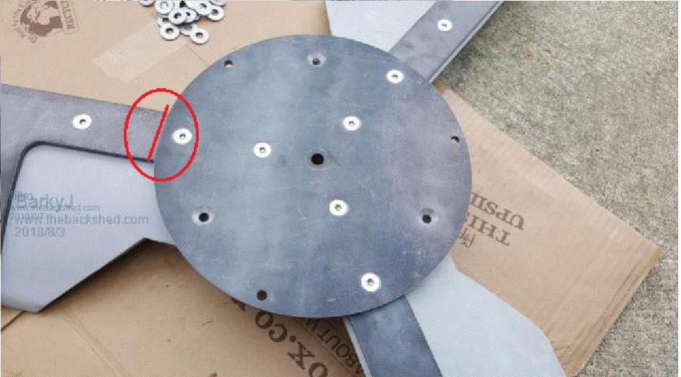 Just to show --Below is a 6mm hub torn apart and the clamps and tube added strength to then allow flexing at the next weakest point. Both of these failures are from the same place in the Strzlieki Ranges behind Melb which I would think is one of the most violent windiest locations in Aus . This particular location 40 - 50klm is just gentle & regularly + 70klm - 100klm gusting, the 12mm x 100mm mounting arm is bent like it red hot . On a previous fail, After shedding the blades and the tail it turned the F&P dual head into an anemometer and I can only imagine what rpm it got to before the abrupt stop. Failure time here is accelerated x 10 compared to even high wind areas. On the up side ,The latest F&P Mk3 the Prototype has been flying there for a good 12mths and being the last F&P / LG design I will do . I will put some pics up in another thread when I get time. 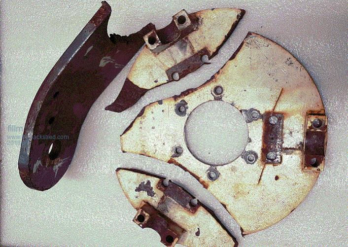 Can you expand on this Theory ? PhillM ...Oz Wind Engineering..Wind Turbine Kits 500W - 5000W ~ F&P Dual Kits ~ GOE222Blades- Voltage Control Parts ------- Tower kits |
||||
Madness Guru Joined: 08/10/2011 Location: AustraliaPosts: 2498 |
The tip speed, blade angles are all based on the wind coming straight at the blades, any turbulence and it is coming in from all over the place. So then the angles are not correct and you don't get full efficiency, as you would know wind generators work much better in clear air unaffected by turbulence. There are only 10 types of people in the world: those who understand binary, and those who don't. |
||||
| BarkyJ Senior Member Joined: 26/04/2018 Location: New ZealandPosts: 114 |
Thanks Fillm, That's a scary picture you posted there. We don't get winds like that at all where I am, however fully taking what you (and others) have said on board. The failure on your hub though seems to be at the end of where the blade would be, like its been levering at that line where the inner clamps have been. Mine has the long plates running under the round hub to the point of the inner CSK bolts, which also has 16mm thick blades running up to that point, and then another thinner plate on the windward side. I'm looking at what I have and would be surprised if it manages to break through all that - but you guys are the experts, not me. As mentioned, it is not just 1x 6mm round plate I have, it is 2 of them. But I have it like this so I can remove the whole blade assembly off the windmill, leaving the 2nd plate attached still which is attached to the generator. I have always been contemplating adding a smaller plate on the windward side, which ties the blades together there, but I originally thought that was going to be overkill. Anyway, tomorrow I am putting the blades on as is, just for a low wind test, we are only expecting like 6-20km/h winds, so nothing extreme at all, but I just want to get them on and see if it spins ok unloaded, and see if the controller is registering all the bits correctly, as its hard to simulate spinning motion while adjusting load - my drills just aren't up to more than about 30s of running. I will be taking it down again the same day. |
||||
| BarkyJ Senior Member Joined: 26/04/2018 Location: New ZealandPosts: 114 |
Question. What's the recommended practice for the stator and weather. Do you need to do anything to protect them like circuit board lacquer or something, or are they fine as is? Thanks |
||||
| Warpspeed Guru Joined: 09/08/2007 Location: AustraliaPosts: 4406 |
I don't see this as an ultimate strength problem, but as a metal fatigue problem. The hub is definitely going to see some very high cyclic stresses that very slightly flex it first in one direction, then in the opposite direction. Fine cracks may begin to appear at the surface at the highest stress points, usually where there are dramatic sudden changes in cross sectional area. Corrosion in these fine cracks may add to your woes, as moisture wicks into the cracks and remains there. Then one day in a fairly stiff breeze that it has already survived countless times it will unexpectedly fail, go out of balance, and then completely self destruct. What you really need at the hub is very high stiffness, which material thickness alone will not usually provide. Gussets, ribs, rolled edges or whatever to make the hub really stiff without being unnecessarily heavy should be the aim. Cheers, Tony. |
||||
| gpalterpower Senior Member Joined: 19/07/2009 Location: AustraliaPosts: 175 |
Hey Barky, Nice build you got going on there buddy. Im liking the nacelle and stepper motor arrangement. Im just asking how you are going to attach the hub to the shaft. Its just that it just looks like a 12mm hole in the centre! Im assuming then youll be placing it on to the 12mm metric thread on one the end of the shaft. Am I correct in saying that, or do you have something else in mind. Thinking you may need a boss to strengthen the attachment point otherwise you may get some serious flexing on that thread! I built a dual bout 5 years ago and I wanted to make sure that it was going to stay together during heavy wind gusts and storms. The good thing is its still flying and it has been thru some horific gale force winds in its time. Marcus if it aint broke dont fix it!! |
||||
| Jarbar Senior Member Joined: 03/02/2008 Location: AustraliaPosts: 224 |
As a rare contributor due to Ill health, but a long time frequent observer I'll chance my hand at the cause of the fatigue cracks on phillm hub disk.On a previous build for karlj the RHS that Phil used for the nacelle had the side torn out of it in an upward direction.This destruction was caused by the gyroscopic force of the spinning blades needing to go somewhere. Caused by the constant and sometimes violent changing of direction of the mill head by the tail trying to track the wind.And the amount of overhang in front of the pole.(longer lever) This causes the mill head rotating around the pole and the gyroscopic forces of the spinning blades to try inducing swinging up as it furls. This can be seen and felt if you spin a bicycle wheel whilst holding each end of the axle and then trying to turn it left or right.In one direction it will swing up and in the other direction down. This upward or downward force is what I believe has fatigued the hub disk. If it is made thicker then the force is transferred to the next weakest point which was the RHS on Phil's karlj mill.A thicker walled tube was used in the replacement and boxed in. I can't seem to find the photo's that were on this site to show the torn metal.But that could just be my lack of investigation. On a mill I made that was designed to tilt up out of the wind it would spiral madly around the pole trying to dissipate this force in a figure 8 pattern, and after many experiments,I designed a better furling method. As BarkJ has a motorized furling system in place to track the wind,I imagine the forces will be less immediate and violent by providing a smoother transition in directional change but not entirely eliminating them.I do agree that a second plate on the opposite side of the blades so that the above mentioned forces are transmitted to the shaft further back than the 12mm threaded section and onto the main shaft diameter other than through the plastic magnet hub. Its been a great project to follow so far and your skills and willingness to present them here are greatly appreciated.Keep up the great work. Lets see if my arm survives!! "Creativity is detirmined by the way you hold your tounge".My Father "Your generation will have to correct the problems made by mine".My Grandfather. |
||||
| BarkyJ Senior Member Joined: 26/04/2018 Location: New ZealandPosts: 114 |
Hi Marcus Cheers - trying to put something into practice, but unsure if I am winning or if it will be a complete disaster yet. Time will tell :) So the single 'old style' male-male shaft connects the two rotors together, and they are on the splines of the shaft, so locked in at both ends. The nacelle and bearing arrangement I have posted about already, determines the spacings and I designed it as such to utilise the correct parts of the shafts, so no cutting or welding of the shafts was needed at all. One end has the longer threaded male end, and this locks to the 2x 6mm plates I have. The other end basically has a flat waster on it and lock nut, and just stops the rotor 'coming off, that end, and pulls the rotor and bearings etc all nice and tight. The first plate has 5x 10mm 'buffered' fingers which go through the peanut shaped openings on the rotor. There are 10 peanut openings on the black rotors, and I have 5 fingers which go through these openings. So as the prop turns, its linked directly to the outer plate, which is bolted to the inner plate, which has fingers which push on the rotor in 5 places, which turns the rotor, turning the shaft, turning the 2nd rotor. Basically. When I say 'buffered', its basically just a pressed on plastic tube over 10mm solid welded in studs into the 6mm round plate. (Ive not pictured this plate to date in my posts). It is a hand pressed in neat fit, so it basically makes the rotor and first plate, one piece, once tied to the centre shaft. There is a 3D printed solid piece which sits between the rotor and this metal plate, which essentially fills in the gap, as the rotor has a stepped section right by the shaft output, and this is not at the same level as the ribs of the rotor, or the edge of the rotor. So I modelled this and printed a plate which levels everything out basically. The 5 metal pins which go from the first plate through the peanut shaped holes of the rotor, pass through this 3D printed plate also. So this plate with the fingers, threads over the 12mm thread on the main shaft, and bolts to the 2nd plate around the edge, but also goes over the centre 12mm shaft too. So no power is directly applied to the spline of the shaft from the prop plate, as both spines have rotors on them. It's a little interesting and makes you go 'hmmmm' a bit, but when you think about it, it's solid as, totally sandwiched and nothing can 'go' anywhere, and should translate the prop power through to the dual rotors nicely. Hopefully. :) Hey, if someone didn't try it, who would, right... I came up with this solution after looking at all the washing machine pieces I had, and started threading bits on to each other, and soon realised that I didn't need to weld any shafts to achieve a dual rotor, and the input of power into the system could be achieved indirectly through the rotor, as long as the pieces were solid in contact and essentially became a single piece. So that is what I set out to achieve and I think I have done so, but we shall see. It might explode  but I somehow dont think it will. but I somehow dont think it will. |
||||
| BarkyJ Senior Member Joined: 26/04/2018 Location: New ZealandPosts: 114 |
Hi Jarbar, Thanks for taking the time to post. Sorry to hear about the poor health, I hope things are going alright. Fingers crossed that my motorised implementation does remove some of this violence you speak about, which comes about from the furling. I am certainly looking into the plate on the windward side to tie things together more. The main issue is I likely won't have shaft thread left at this length away, due to how think the blades are etc, but I am thinking of a solution to this and might have something in mind. Cheers for the support. Fingers crossed things work out OK. |
||||
| BarkyJ Senior Member Joined: 26/04/2018 Location: New ZealandPosts: 114 |
So today I took a few hours and did some more work on the windmill with my old man. We bolted the prop and outer plate onto the windmill, and started checking clearances, and soon discovered a major issue which was just a stupid oversight. The props do not clear the turret motor, so the pictures I have put up previously are going to change again, as I need to move the motor to the side of the pole. Not a huge issue, but just a pain in the bum. We put a piece of box section on the side of the pole, which is what the motor was bolted to, to turn the turret around. But what I didn't consider is how far it sticks out, and when the windmill turns around to be on the motor side, just how little (or no) clearance there actually was. The box section was added for ease of bolting on the motor, but turns out its the cause of the clearance issue. So what I did today was start off the mounting again, but I put the motor on the side of the box section, rather than on the top, so we gain 40mm of clearance. I will finish this off tomorrow hopefully, weather permitting. I then need to design new brackets for the Encoder and the Home position sensor (grrrrr), as the chain length has to change again, and so the encoder can't go where it was, yadda yadda.... Back to the drawing board for those, but all will be fine. Just some days of work lost. stomped on. plans ruined. world is ending... you get the idea :) I should have it sorted by Saturday though. So after that was discovered, we decided to just try out the winch system after all the weight is now installed. Well, another issue was found. The winch setup we have is a laminated plank, fixed to the ground about 1m from the base of the mast, which stands vertically, but slightly leaning towards the mast. It is about 4.2m in length, so ends above the hinge in the masts pole. The board has 2 steel cables going off to anchors, which are positioned behind the plank, away from the mast, allowing it to sit leaning slightly towards the mast, but supported by the cables, and the ground. We then have a hand winch on the plank, the cable goes up into a pulley, out to one of the Eyes where the 3rd guy wire cable attaches to which secures the mast when erected, into a hook with a pulley on it, then back to the top of the plank into an anchor. As you crank on the handle, it pulls the cable through the pulleys and pulls the mast up. When the mast is up, its bolted at the hinge, the guy wires are tensioned, and the plank/pulley/winge arrangement can then be moved out of the way and stored, leaving the mast with its guy wires in place. Well, the issue is the plank isn't strong enough. It started bending too much, so before it busted we took it down, and bolted on a 4x2 to the back of it, and tried again. Still not strong enough. So we brought some 50x50x6mm angle iron, and bolted that to the back of it, pinned back into the 4x2 also, and now it's good and strong (but weights a stupid amount and is a bit of a mission to handle now - grr). So now the plank is strong enough, tested again now show an issue with one of the anchors which support the guy wires into the plank, one started to remove itself from the ground. It was not as robust as the 3 which support the mast guy wires we never intended it to have so much strain on it, but it appears this is a heavy sucker! So we post hole bored in a new one, deeper and bigger, and now that all seems fine. But now the eye bolts we used, started opening up. They were a non welded type, 8mm galv. Not good enough now with all this weight. Again, this is just the winch stuff, not the main mast equipment, that was well over spec'ed. So tomorrow I need to get some bigger ones, welded type, and replace them. Sigh - all a bit heavier than I was expecting I guess, and it just the initial lift which is the heaviest. Once it gets beyond about 120 degrees the weight comes right off. So instead of today with our 4m/s wind having a little test of all the systems, turned out to be issue fixing and getting wet in the rain, and still a few steps behind. Oh well, all part of the learning. Luckily nothing broke, issues were found and are being rectified. Fingers crossed for something spinning as a test early next week. |
||||