
|

|
Forum Index : Electronics : Warpspeed’s MOSFET mounting method
| Author | Message | ||||
| Warpspeed Guru Joined: 09/08/2007 Location: AustraliaPosts: 4406 |
Kanchana, parts were posted nine days ago, should arrive at any time now.... Australia post claim 8-10 days. Just had another brain storm of how to more simply provide dead time using the inverse opto isolator trick. Just place a capacitor across both the opto isolators. That slows down the transition time through zero, where both opto isolators are off, and increases dead time from 50nS (no capacitor) to maybe 2.5uS with 10nF. The gate drivers have fast Schmidt triggers so this does not slow down the edge speed. Easy to get any dead time you want, and its symmetrical both ways. The whole circuit gives very high noise immunity, completely isolated grounds, cross conduction protection, and now adjustable dead time as well, and with only one extra component. Noise immunity could be an important factor where the heat sinks are "live" and switching up and down very fast at relatively high voltage, and the gate driver cables are quite long. 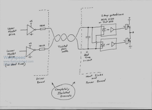 Cheers, Tony. |
||||
| kanchana Regular Member Joined: 08/05/2018 Location: Sri LankaPosts: 56 |
Thanks Tony. Still not received, but will get soon ..  I was playing with eagle , still not finished the board 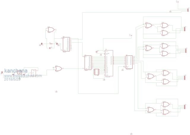 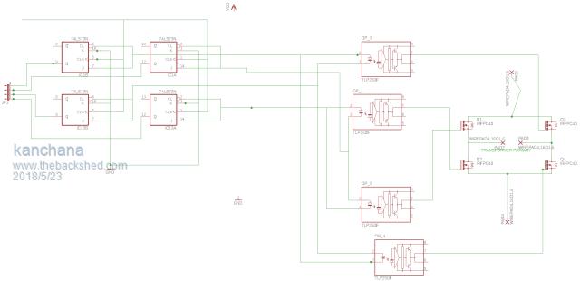 Nice Now I can get rid of the 74HC73 and add the new method of dead time control . Regards kanchana |
||||
| Warpspeed Guru Joined: 09/08/2007 Location: AustraliaPosts: 4406 |
In my case that will eliminate the need for sixteen flip flops or eight IC packages, a very worthwhile improvement. Cheers, Tony. |
||||
| kanchana Regular Member Joined: 08/05/2018 Location: Sri LankaPosts: 56 |
yes Indeed Regards kanchana |
||||
mackoffgrid Guru Joined: 13/03/2017 Location: AustraliaPosts: 460 |
Hi Tony It's been a long time since my last post, life has got in the way again .... My state of progress was that I've assembled and tested the PCBs and large transformer wound. Still need to put a big lug on it. Any clues on the best way to strip the enamel? I see that you have had quite a few neat ideas since I last checked in. I had provision for a processor board to select one of 32 maps in a 512kb eprom - which I thought would be reasonable, but changing to a 1k map, if that doesn't increase distortion, and going for a 2Meg eprom would be cool. The map addressing is only latched in at the beginning of each cycle so that the proc doesn't have to work hard. I like your idea of directly using an ADC to directly address the map - but I had the idea of building another one of these just to run the Hot Water Service but be able to modulate the power to available free solar power - with no battery cycling. Regarding regulation: I'm not too hung up it and you idea on regulation on battery voltage sounds fine to me. (I was going to see how it goes with no regulation) RE: Clamping: Considering all the extra Fets, PCB (in my case), and wiring; I like the simplicity of using the existing H bridge to clamp the transformer. I will study the circuit changes and how I will approach it. Testing: Can I test the system with Just the large transformer without the others or will it be too harsh on the clamping fets (clamping on secondary) without the other transformers? I was thinking of using 40 watt globe a load. RE HWS: Do you think a 2 transformer inverter would be ok? Would the same go for a heavy duty inverter to start/run air compressors and car hoist? Regards Andrew |
||||
| Warpspeed Guru Joined: 09/08/2007 Location: AustraliaPosts: 4406 |
Andrew, the first one of these step inverters I ever built (now almost forty years ago) used a 68H05C8 processor with 16K of internal eprom. It used three inverters giving 27 voltage steps peak to peak, with fifteen 1K lookup tables. Still have that original inverter around here somewhere. It worked very well for what it was, only 500 watts with 10v to 15v dc input. It was just a toy really, but it certainly proved the original basic concept to be very sound. Thirty two lookup tables is certainly very workable, and 1K lookup tables provide more than adequate 20uS time resolution for any number of inverters. My latest effort powering my house right now uses 256 1K lookup tables which is vastly more than is really necessary. probably 64 or 128 lookup tables I suspect would not make any noticeable difference. The transformers must be designed to provide the required voltages, and the required output voltages for each transformer will be different depending on the number of inverters you plan to eventually have. Assuming we are designing for 235v rms final output, which is 333v peak. If you only plan to build a single transformer very crude square wave inverter, it will obviously need to have a 333 volt rated secondary. A two transformer inverter will need to reach the same 333v with both secondaries aiding, and have a 1:3 voltage relationship. So the big one will be roughly 250v and the small one 83v. Three transformers also need to add together to provide 333v peak, in ratios of 1:3:9. So the big one will need to be 231v, medium transformer 77v, and the small one about 25.6v. Four transformers, big one 225v, medium 75v, small 25v, tiny one 8.3v. That also adds up to 333v with relative secondary ratios of 1:3:9:27 So before you start winding transformers you need to pretty much decide right at the start how many inverters you plan to eventually have. Three work perfectly well for all practical purposes, but four give a much smoother final waveform. As your rom will have eight bits, and the fourth inverter is very low power anyway, might as well have it there. I would also suggest you fit an electrostatic screen between primary and secondary to eliminate any voltage spikes on the square wave output of each transformer. I did that and all my steps were beautifully clean. I suspect I may have had some nasty switching spikes had the screens not been there, but was not game to try that. I have now built several quite different versions of these step inverters over the years, and each one has been simpler requiring fewer parts. The current 5Kw inverter control board uses an Intersil twelve bit dual slope A/D converter to address the high order eight bits in rom. Low order ten bits of rom are continuously clocked from a 3.2768Mhz crystal oscillator module. The A/D converter starts a conversion every 40mS and its output is latched into the rom every second cycle right at the zero crossing. The dual slope averaging is extremely accurate and consistent, and gives very good noise immunity to inverter ripple voltage on the incoming dc bus. 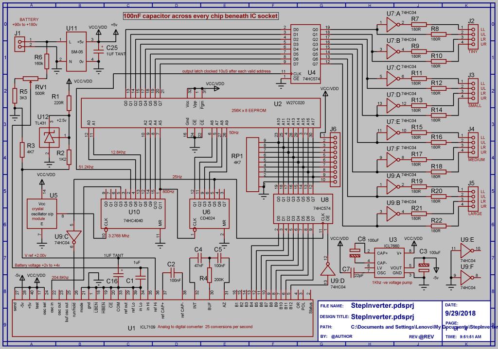 Rom output is latched when data is stable, and that is about it. Each latched data bit drives an opto isolated gate driver direct through a 180 ohm resistor, and the opposite complimentary output comes straight off a 74HC04 inverter. Four bridge inverters, sixteen opto isolator outputs from the driver board on four different plugs. 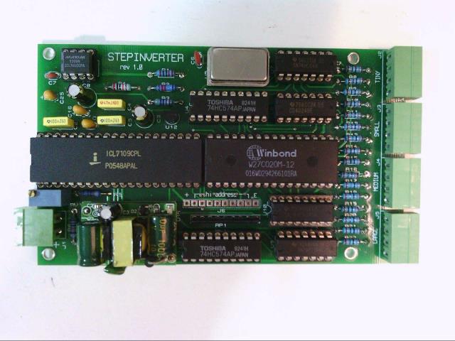 Plus five volts comes from one of those two dollar Chinese postage stamp sized switching power supplies, and minus five volts (for the A/D) from a voltage pump chip. Battery voltage powers the board and also provides the measured input for the A/D converter. There is an absolute minimum of wiring and absolute simplicity. There are ceramic bypass capacitors across every chip located directly under each chip, the sockets have enough height to allow that. Its all very basic. no soft start, no over current protection, no dead time in the waveforms from the control board, no voltage feedback and no microprocessor. And it works perfectly well direct from the solar panels without having anything in between except 36,000uF. Voltage swings from solar are massive direct off the panels, as you might expect, but the output hardly varies at all, certainly not enough to worry about. In fact its BETTER than a PID feedback control, simply because its much faster reacting and completely stable. Overload just trips the ac circuit breaker on the output. The whole thing has enough balls to do that very safely. I have been completely off grid now for six weeks without a single problem, and the inverter worked very first time it was powered up without a single problem. Each inverter consists of a pair of modular half bridge driver boards. These just plug into the control board via a single twisted pair. There are eight of these small half bridge boards. These also are as basic as can be, with just a 15v isolated gate supply and an opto isolated gate driver chip (with inbuilt 11v undervoltage cutout) for each upper and lower mosfet. A small capacitor across the inverse connected opto isolators provides dead time. 1nF about 300nS for the mosfets, and 10nF about 2.5uS for the IGBTs. The whole inverter has eight of these small half bridge driver boards. 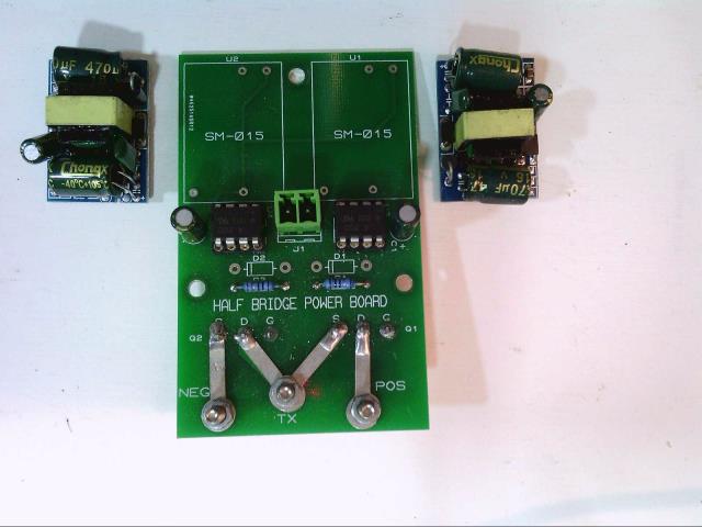 And that is about it. The two smaller inverters just use individual mosfets fitted to screw terminal blocks and PCB tracks reinforced with solder lugs fitted both sides. The two larger inverters use 200 amp IGBT modules that plug into the same identical half bridge driver boards. These particular IGBT modules are rated to carry 1,000 amps of fault current for one full 10mS half mains cycle, which is much more than is required to very quickly trip a normal C curve thermal/magnetic circuit breaker. That is something mosfets just cannot do as well as an IGBT. It would be very easy to scale this up to 10Kw or 50Kw without any of the high frequency problems the PWM guys are plagued with. And its much more simple to build and get going. Only really two obstacles to overcome, fabricating the four transformers is a bit of a pain, but its fairly straightforward, just work. The other is getting suitable lookup tables organized. I just wrote a program in assembler to burn a prom directly. That is no more difficult or complex than stuffing a working microcontroller into the inverter. But a bare rom has the advantage of not having any timing constraints. A bare hardware rom is simple, and a lot more robust IMHO, than running a live software program in an inverter. 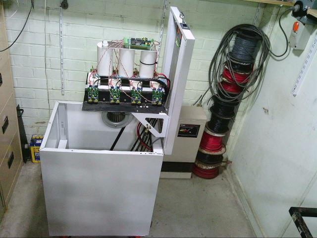 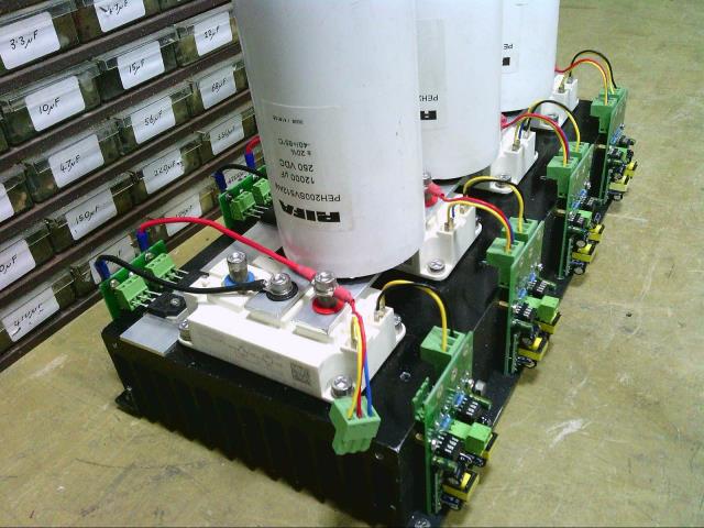 If it ever does spit the dummy, everything just unplugs or readily unscrews, and I have spare boards ready to go. Accessibility is particularly good too in this version, although its physically rather large. I should be able to fix a blow up very fast without requiring mains power or a soldering iron. Cheers, Tony. |
||||
mackoffgrid Guru Joined: 13/03/2017 Location: AustraliaPosts: 460 |
Thanks Tony Lots of information in your post to digest. The whole thing looks great. The AD circuit is simple and very effective, quite a task maintaining regulation from solar panels. In my case it be hanging off batteries so I reckon I could live without any regulation if I had to. Amazing how simple the logic for driving the FET drivers has become, and losing the extra clampers by using the main H bridge. I see you no longer use the 7667's. I've already wound the primary onto the big transformer, no screen :-( I'll see how that goes. What's the part number of your IGBT's? I'll stick to FETs at the moment but I may go that way if I want to really guts it up. Cheers Andrew |
||||
| Warpspeed Guru Joined: 09/08/2007 Location: AustraliaPosts: 4406 |
I keep thinking of sneaky ways to simplify things and use fewer parts without sacrificing robustness or reliability. The big inverter killer IMHO are the chaotic and unpredictable conditions that can exist at power up, and especially power down, and even an occasional brownout. If we can design the power stage so that any incoming drive pattern 00, 01, 10, or 11 to the bridge is harmless, and we are completely protected from upper/lower cross conduction, a great many possible failure modes will be guarded against. The other important aspect is high noise immunity, keeping the extreme electrical violence at the bridge right out of the driver and control system. Don't worry too much about the electrostatic screen. If there are very narrow microsecond wide spikes on the secondary, an effective EMC mains filter will very likely get rid of most of it. Its just something to think about when planning the next transformer. Also, wind all four transformers as though they were just for 50Hz. The smaller ones will be switching faster than that, and have higher relative losses. So winding for a low flux density at 50Hz will mean the flux in the smaller transformers will be even lower. This reduces the idling current losses in the smaller transformers that would otherwise have higher eddy current and hysteresis losses at the slightly higher switching frequencies. Design each transformer as if it was for 50Hz, that simplifies things a lot and will give excellent results. I have had these Semikron SKM-200-124GB devices on the shelf for years, and was glad to finally find a use for them. Many similar devices on e-bay some even larger. They go for around $80 to $100 new and about $50 secondhand. Not exactly cheap... A prototype with mosfets or smaller TO247 IGBTs will be good for several very reliable kilowatts with only four devices per bridge. Nothing wrong with paralleling up multiple devices, and its easier to do well than at the higher PWM frequencies. I used the outrageously expensive big boys simply because I already had them, and it provides a very neat and compact mechanical solution. Mosfets would be much more suitable than IGBTs at lower dc voltages and high switching frequency PWM. At higher dc voltages and ultra slow switching rates, IGBTs are far superior, more robust, and a lot easier to drive at very high power levels. Cheers, Tony. |
||||
mackoffgrid Guru Joined: 13/03/2017 Location: AustraliaPosts: 460 |
Do you have a fan cooling that lot down? or just passive cooling? |
||||
| Warpspeed Guru Joined: 09/08/2007 Location: AustraliaPosts: 4406 |
When the hinged lid is down, the heat sink fins are vertical and it passively cools through convection. I have a 240v ac powered digital temperature controller mounted on the front of the lid that displays heat sink temperature. That can start up a pretty potent 240v centrifugal air blower salvaged from a Rinnai gas room heater. This LED temperature display also indicates that 240v is present at the inverter output. There is a picture of the blower mounted beneath the heatsink on the previous page of this thread. The blower blows horizontally into the centre of the vertical heatsink when the lid is down, so the air splits, half going upward, the other half blowing downwards straight onto the transformers located below. Flow areas through the blower and through the fins are a pretty good match, and it provides very effective and silent cooling. Its an unusual way to cool a heatsink, but it works amazingly well both freely convecting, and forced air cooled. This shows relative sizes and flow areas of blower and fins. 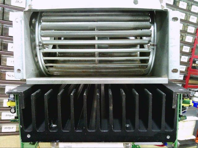 Cheers, Tony. |
||||
mackoffgrid Guru Joined: 13/03/2017 Location: AustraliaPosts: 460 |
I decided to mod my boards to use your latest driver idea as it makes testing so much easier. A bit of veroboard and its done. I'm also adding a Set Reset latch to control the clock. I did make a SMPS with 12 isolated outputs to drive everything. I measured the current needed to supply one opto driver in operation and it was only about 10mA - so next time I'm going to use those tiny PCB mount 12 to 15v 2W isolated supplies. B1215S-2W Where did you get those ACDC 15v boards from? all I could find were 12v. I can't imagine they'll work off 24 battery but they'd be handy as isolated PSU's for testing purposes. |
||||
| Warpspeed Guru Joined: 09/08/2007 Location: AustraliaPosts: 4406 |
Its really weird, but many months ago I bought a large number of 5v, 12v, and 15v versions of those small isolated supplies. For some reason there are no longer any 15v ones being advertised. I am sure they will eventually return, as all the other voltages between 3v and 18v are still available from multiple different sellers. Anyhow, I used up all the 15v ones I had, and was still short a couple. So I discovered its a pretty easy modification to turn the 12v output supplies into 15v output supplies. There is a resistive voltage divider across the dc output to provide the appropriate voltage feedback, and the upper resistor of that was 1K8. By changing the upper resistor in the divider to 2K4 that produced a very nice dc output of about 15.1 to 15.2 volts. Altronics have the 2K4 surface mount resistors. As these supplies are rated up to 450mA full load, and we only need about 10mA it will do all that very easily, and they start up at around 35v dc input with the ultra light loading on the output. Seventeen of these supplies (16 x 15v) and (1 x 5v) draw only five watts of idling power total for all of the electronics for the whole inverter. The rest of the inverter idling power will be made up of just the magnetizing current for the four transformers. In my case that is 30 additional watts. Cheers, Tony. |
||||
mackoffgrid Guru Joined: 13/03/2017 Location: AustraliaPosts: 460 |
This one looks to be the same AC DC 12v 400mA |
||||
| Warpspeed Guru Joined: 09/08/2007 Location: AustraliaPosts: 4406 |
Yup. So cheap its not worth considering using anything else. Cheers, Tony. |
||||
mackoffgrid Guru Joined: 13/03/2017 Location: AustraliaPosts: 460 |
Hi Tony I'm very Pleased - I run up the transformer today ; No problem at all. I incorporated a 2 button inputs, Start and Stop, that are latching to help in the power up and de-powering, made my life much easier, as I have no spare FETs to blow up. Ordered 100 lot last week :-) Here is a photo of the transformer output. That 20v represents 219v which is pretty right since the test battery voltage is about 1v too low. 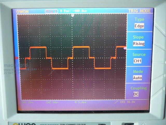 Im not bothering with load test yet, I'll build the 2nd transformer, by then I'll have more fets. |
||||
| Warpspeed Guru Joined: 09/08/2007 Location: AustraliaPosts: 4406 |
That looks excellent. Here's my big #1 transformer waveform which looks identical. 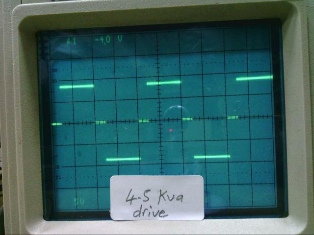 Cheers, Tony. |
||||
mackoffgrid Guru Joined: 13/03/2017 Location: AustraliaPosts: 460 |
Hi Tony I stripped down the #2 transformer and I'm going to re-use the inner winding as the secondary (110 turns of 4.9mm2). I have left the screen on this transformer. I understand the screen is meant to capacitively couple the 2 windings but isn't it meant to be a single turn connected at one end only ? This screen looks like the Aerosharp screen where they wind a laminated copper tape around the core creating another winding? 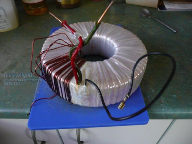 |
||||
| Warpspeed Guru Joined: 09/08/2007 Location: AustraliaPosts: 4406 |
I have never attempted to fit a screen to a toroid myself, but I did suggest at one time it may be a solution to the occasionally observed "kink problem" for the guys running unipolar PWM. The problem seems to be more theoretical than practical and just may not arise, but its something worth knowing about, and to be aware of. Any stray capacitive coupling between primary and secondary can theoretically induce a voltage spike into the secondary waveform with very fast switching primary. It may be at its worst where the primary switched voltages are fairly high, and the secondary voltage is much lower, due to a large step down turns ratio. When its the other way around, a lower switched primary voltage, and the transformer has a high step up turns ratio, the spike problem should potentially be much less. I have never actually had this problem in any of my own inverters, so its probably nothing to worry about. If your #2 toroid already has a screen fitted to it, I would just use that as is, and see how it goes. Cheers, Tony. |
||||
mackoffgrid Guru Joined: 13/03/2017 Location: AustraliaPosts: 460 |
I have my No#3 transformer core. Its out of a latronics GTI. It has a 32v winding at about 4mm2 but unfortunately its on an outer winding. What's your thoughts re: leaving the old 240v winding (and a aux 20v winding they use for fan) on the core and wind my new primary over the top of it all? |
||||
| Warpspeed Guru Joined: 09/08/2007 Location: AustraliaPosts: 4406 |
The core is probably larger than it needs to be for #3, but that is good. I suppose its a question of is there enough room left for the new extra winding ? Cheers, Tony. |
||||