
|

|
Forum Index : Electronics : building an Inverter from scratch
| Author | Message | ||||
| Tinker Guru Joined: 07/11/2007 Location: AustraliaPosts: 1904 |
here is a little more progress on the cores. I ended up with a pile of stuff to recycle. 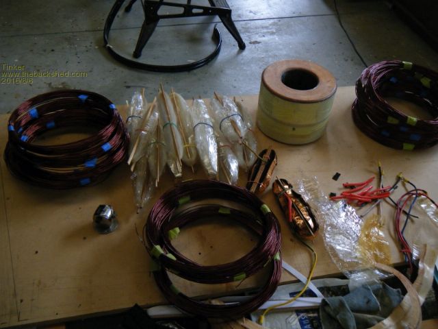
The two cores were epoxied together to make a twin stack. I used a fiberglass cloth with fortified epoxy in between them to make up for the slightly uneven surfaces. With my single core project (tinkers inverter project) I had not bothered to round the corners of the core and regretted that when winding the first layer of wire on. This time I made two disks from 6mm plywood and epoxied these onto each end of the core. 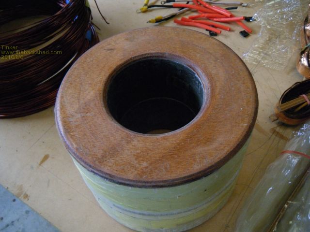
This was easy to do in my lathe but, of course, the stack becomes 12mm higher that way. This may be too much for those who try to use the original Aerosharp 3Kw enclosure to house their inverter. For my project, that enclosure was way too tight already when I fitted my single core toroid inside, so this time I'm using a different enclosure. It will also allow me to mount the twin stack toroid with the mounting bolt vertically oriented, so that the heavy weight rests on the bottom rather than being suspended from that single bolt. I marked my core in a different way than mentioned in madness's thread. 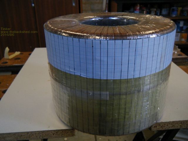
Using this home made device to draw the radial lines. 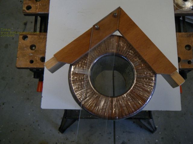
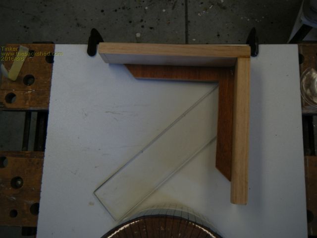
Oztules wrote a great post, somewhere among the 60,000 words he wrote on this subject, on how to wind a toroid core. The gist was to wind the wire two turns side by side, then a gap for two wires before the next two turns side by side. That is on the outside of the core. Through the hole the wires have no spacing between the adjacent turns. Doing it that way naturally aligns the next layer of turns into those gaps so the winding proceeds in a neat fashion. But, the wire *must* lay radially and not skewed sideways over the core ends, this is why the radial marks are important. So my twin stack core is now ready for winding the 4 in hand x 100 turns of the 230V secondary onto it. Let the fun begin  Klaus |
||||
oztules Guru Joined: 26/07/2007 Location: AustraliaPosts: 1686 |
Your meticulous eye for detail blows me away each time you do something.. I have decided I fit into the rabble spectrum for sure.  ... ...
Madness is doing meticulous work too...... and Clockman...... gee... I have been completely eclipsed .... and I am pretty happy about it as I have learnt a few things from you folks as well. Look forward to the next installment 
...........oztules Village idiot...or... just another hack out of his depth |
||||
fillm Guru Joined: 10/02/2007 Location: AustraliaPosts: 730 |
Hi Klaus As always very nice work and follow your progress with intrest. The radius ply ends are a good idea but question will it effect the efficiency or workings or even allow the windings to fret and vibrate into it over time . Why not just radius the core with a grinder and flap disc? PhillM ...Oz Wind Engineering..Wind Turbine Kits 500W - 5000W ~ F&P Dual Kits ~ GOE222Blades- Voltage Control Parts ------- Tower kits |
||||
| Tinker Guru Joined: 07/11/2007 Location: AustraliaPosts: 1904 |
Two reasons, first, the ply disks are way less work than messing about with angle grinders and flap disks. second, I did not like the idea of loosing even a tiny amount of core material 
The windings will be epoxied at each layer to stop any vibrations. I expect my transformer to be much quieter than the original donor was. As to efficiency, yes there will be an increase in wire length of about 25mm per turn of wire. A rough calculation adds an extra 2.5m wire to the copper resistance of 1.8mm diameter wire per hand. However, I'm using 4 in hand of 1.8mm wire, 10mm sq in total, for the secondary. A conservative current capacity for transformers is 3A/mm sq. Since it is very unlikely I'll be trying to drain nearly 7Kw from my batteries for any longer than a few seconds the small added wire resistance is more than compensated by the generous wire cross section at my usual power drain figures. Klaus |
||||
| Tinker Guru Joined: 07/11/2007 Location: AustraliaPosts: 1904 |
Faced with winding my double stack toroid core a decision on how to go about it had to be made. I really liked the fishing reel method I pioneered in 'tinkers inverter project' but this type of reel has too small a diameter for a double stack core. I required something like it but bigger. But what? Perhaps a ring made from that black split conduit? No, its too flexible. A ring made from black 19mm poly pipe? Yes, that might work. Then I had another lightbulb  moment, how about two rings? They would be stiffer and let me wind two hands of wire at once. moment, how about two rings? They would be stiffer and let me wind two hands of wire at once.
How hard could that be? Well, somebody had to try it to find out. 
So I set about making this contraption. 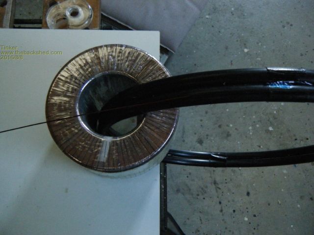
I wound some gaffa tape around to hold the two rings (about 600mm diameter) together. Then I used a stanley knife to saw a split around the outer rim of each ring. After this the rings were a bit flexible so I tried to glue them together as well. But nothing seems to stick to that black poly something material. What you see in the picture is something like liquid nails, it too does not adhere well. Anyway, I started loading these circular wire dispensers, one at a time. 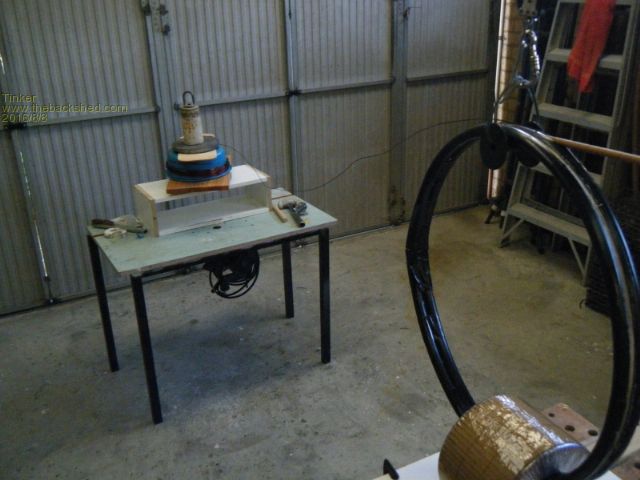
The wire spool sits on a rotating table (cake decorating bearing) I used a dowel to slide along the slot to open it so the wire could be loaded. 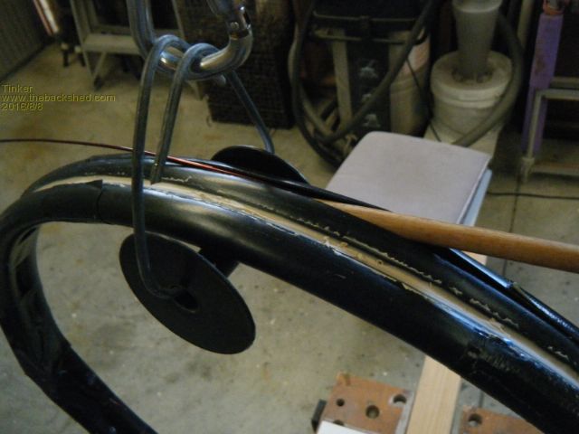
Once both dispenser tubes were loaded with wire they were markedly stiffer and I started the winding job. The lines I marked on the core for the wire spacing were very helpful. A comment about this spacing; Measuring the inside diameter of the prepared core I could calculate how many closely spaced turns I could fit there. But its too optimistic to assume the wires will be really close spaced. I learned that the hard way when doing the single core toroid. So I used a spacing of 2mm per wire for a 1.8 mm diameter wire. I also used an inside core diameter of 2mm less. That worked remarkably well for me. There was room for 76 turns of 2 in hand wound simultaneously. So there would be an overlap of 24 turns to complete the first part of the wind. By sheer coincidence there was just about the right length of wire loaded in my dispenser. I knew the wire was not long enough for 100 turns and I had to splice it somewhere. But this way I could stop the winding job at a convenient place and insulate the first layer. 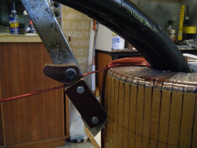
The gadget shown above is something I made to tension the 2 wires at each turn. It works but I wish I had made the cam lever twice as long or more. My thumb got sore having to push the cam down hard to lock the wire. The fabric loaded bakelite (Can't think of the trade name for this) I used works well. Its hard enough not to groove but does not harm the wire enamel. This is how the first layer looks like: 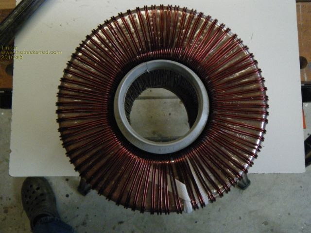
The plastic plumbing fitting in the center hole is there to push the wires firmly out while I epoxy the wires there. I do that from each end which locks the inside of the turns solid. I also did insert a bit of 2mm whipper snipper cord between the last and first turn to keep them spaced apart. After the epoxy has cured a full cover of mylar tape will go on to lock the outside of the turns in place. 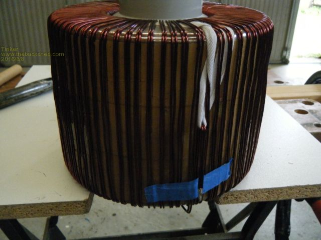
This pic shows the wire start, I soldered the two wires together to keep them that way. The spliced on wires will be done on top of the mylar tape. Klaus |
||||
Madness Guru Joined: 08/10/2011 Location: AustraliaPosts: 2498 |
Looking good Klause, I started out with an Aluminium bike rim like Frackers on a different forum that Oztules posts on, which is much the same as what you have done. However, I switched over to the same method that Oztules used, I found a roll of heavy resin core solder that had the right size spool. By getting a screwdriver with a handle that was a close fit to the inside and adding some masking tape and jamming the spool on, then putting the shaft of the screwdriver in a variable speed drill I could wind it on easily and quickly. The wire I used was about 8 m longer than needed, so I ended up with no joints in the windings. The reason I changed methods was I found that it was quicker and the small diameter spool unwound flat against the core. That solder spool worked until I got to the primary windings, then I had to change to a smaller spool to get through the hole. I know you are not planning to do the primary that way but that was my method. Winding the Torroid is certainly the sexiest part of the Inverter build. There are only 10 types of people in the world: those who understand binary, and those who don't. |
||||
fillm Guru Joined: 10/02/2007 Location: AustraliaPosts: 730 |
Hi Klaus, As usual a very good standard of work and very good ideas with winding and getting the windings nice and tight. A question has been in my mind about using epoxy because of the experiences with epoxy and the AXFX alternators. Why is every one wanting to epoxy the windings in place but in the same breath also worried about the temperature the toroidial will operate at? As soon as you coat the copper with epoxy to a degree you diminish its cooling ability, when manufactured toroids seem to operate well with no problems and with out epoxy. With the quality of keeping the tension that you/mads are attaining is it really necessary? Anyway please keep the build and pics coming and watching respectfully your workmanship. Phill PhillM ...Oz Wind Engineering..Wind Turbine Kits 500W - 5000W ~ F&P Dual Kits ~ GOE222Blades- Voltage Control Parts ------- Tower kits |
||||
Madness Guru Joined: 08/10/2011 Location: AustraliaPosts: 2498 |
From what I have read from Oztules the epoxy is to stop the wires vibrating and failing prematurely. The Aero Sharp Inverters have a bad reputation for annoying buzzing which is caused by the Torroid and the people I got them from said they had quite a few transformers fail. Oz also has said the small amount of Epoxy would help distribute the heat and aid cooling, but I am but a mere mortal following the guru. I quote here from Oztules "One interesting thing of using the epoxy, is that it helps the cooling, stops the noise, fills in any micro cracks in the second hand wire.... and also gets slimy when still runny. This allows you to fairly easily move the wires around on the plastic substrate very easily... for cosmetic purposes. So while the wire is tight and does not want to move in that picture, tomorrow when the epoxy goes on, it will be easy to tidy it up some... and hopefully make it symmetrical. This looks better... but importantly makes making the third layer the same as the second, as the wiring will simply fit in the gaps again, making it easy to keep the turns the same..." There are only 10 types of people in the world: those who understand binary, and those who don't. |
||||
| Tinker Guru Joined: 07/11/2007 Location: AustraliaPosts: 1904 |
Yes Phill, IMO epoxy coating is very necessary. Don't forget that I'm coating the secondary winding, which on this toroid is wound *inside* the primary. So, its encapsulated by the primary winding and the electrostatic shield layer plus the mylar tape insulating layers. Really, epoxied or not makes no difference at all to the heat dissipation in this application. Epoxy is good for 100 deg C or so before it gets soft. I sincerely hope my toroid is *never* getting anywhere near that temperature. If it did, as some epoxied motor armatures do, there are high temperature epoxies around. The very best thing you can do to keep your toroid windings cool is to oversize the copper wire cross section area to lower its resistance and, therefore, warming by the current flowing through it. Another important thing is to keep the toroid well ventilated and away from radiating heat sources such as the mosfet heatsinks. And I'm doing just that. Klaus |
||||
fillm Guru Joined: 10/02/2007 Location: AustraliaPosts: 730 |
Klause, When thinking more I suppose in the main stream where big toroids are mounted with the middle filled with resin and they are bolted down giving probably at best 50% exposure to cooling air flow. I would say that if the efficiency is high then of course heating is minimum and as you say the more mm˛ copper the better . Then all the wrapping of mylar or Kapton again limits cooling and the list goes on. Having good cooling fans and giving more air flow in the mounting design will help if of course if the inverter is pushed to its limits for lengthy periods. It seems that these inverter builds are pushing the limits of design that can not be built into production inverters because of the cost factor and its good to see especially at the end when testing the limits . Mds - I think you have been staring at the big round hole for to long.  PhillM ...Oz Wind Engineering..Wind Turbine Kits 500W - 5000W ~ F&P Dual Kits ~ GOE222Blades- Voltage Control Parts ------- Tower kits |
||||
Madness Guru Joined: 08/10/2011 Location: AustraliaPosts: 2498 |
Actually, it is the curves that do it for me.  There are only 10 types of people in the world: those who understand binary, and those who don't. |
||||
| Tinker Guru Joined: 07/11/2007 Location: AustraliaPosts: 1904 |
Oztules, I hope you are reading this as I would appreciate your advice. Before I started dismantling my Aerosharp toroid core I measured the core excitation current at the 230V winding. It was 71mA when the input was exactly 230V on my variac. Now I have finished winding the 100 turns, two in hand, of the 230V secondary. Another 100 turns still to come, to give me 100t of 4 in hand. I thought I should power it up and see if everything is OK. The twin stack core demands an excitation current of 120mA when powered from the same variac set to 230V. That is around 28VA, does this sound in the ballpark? I could easily add more turns at this stage if you think that might be worth while. A picture of the test: 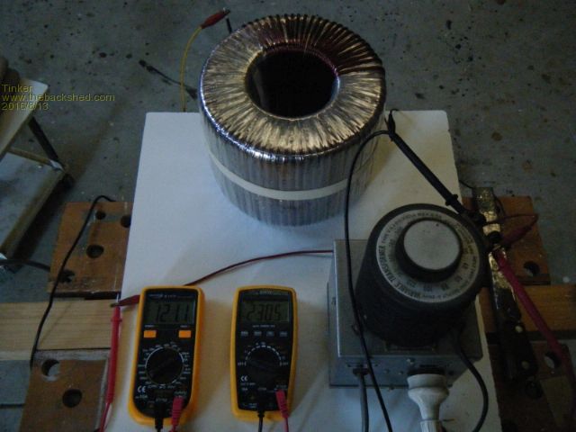
Close up of the DMM's: 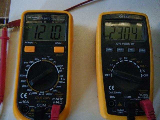
Oh, just out of curiosity I put a temporary short turn around the core to see how much different the meter reading is. Cranking up the variac slowly, the current shot past 1 Amp at around 150V when I stopped as the variac is not rated higher. The short turn gave the magic smoke signal by then. So, it is *very* obvious if anybody gets a shorted turn at their rewinding exercise  . .Klaus |
||||
oztules Guru Joined: 26/07/2007 Location: AustraliaPosts: 1686 |
Ok Tinker. I'm not an EE but this is what I see and want you to try. Simply we have twice the core mass than you had before, so i think your doing well... less than twice for twice the core. I think your thinking you are near saturation or worse, and this is what is causing it.. I don't think so..but it is easy to test as you have a variac. I think if you move the voltage higher ( to 240, 250 260 ) you should see a linear increase if your away from saturation... if you see a sharp non linear rise, then your nearing saturation... so should be easy to spot.. and at saturation it will be awful. If you look at the graphs of a transformer, you will see it is non-linear as you get nearer to saturation.... this is why i think as above. If you see that it is rising exponentially fast as you near 230-240v, then I have fouled up the calculations, but i think your in the sweet spot. Now you can tell us what happened. If it is too close to saturation, then more turns... but I hope not. So if your still in the linear part of the curve your doing fine. EDIT... just realised you said 100 turns, so i assume you found 1.2v/turn on the original single core.. I seem to remember 1.14 for mine, but that may be the inspire one....  too many cores... too small a memory... If yours was 1.14, then we may be a bit skinny. too many cores... too small a memory... If yours was 1.14, then we may be a bit skinny.
====== Epoxy cores.... well I have seen and fixed several high end inverter torroid transformers, inc aust made name brands. When you see how they are wound, you have to wonder why so few, it is terrible, relying on thin films of insulation between high differentials is staggering. The vibration will get them eventually, but it takes longer than I would have thought, but it happens eventually. EI types never fail from that, usually just overloaded and burn up, the potting precludes the vibration attrition. If you put a few thousand volts through torroids, as a general rule they will fail in a few seconds to a minute ( micro second pulses spaced a second apart ), as the interwinding potentials are too much too close. EI will run for many many minutes. This is extreme insulation testing.... but tells you a lot about the winding safety. And finally, if your using the old wire after straightening, then there will be micro fractures in the enamel... the epoxy will help make our reworked wire much less prone to failure. .............oztules Village idiot...or... just another hack out of his depth |
||||
| Tinker Guru Joined: 07/11/2007 Location: AustraliaPosts: 1904 |
Thanks oztules, You may not be an EE but you are doing much better than some EE's I met during my working life when it comes to explain things electrical in simple terms the average bloke, like myself, can easily understand. And you saved me a lot of money in the bargain by posting your expertise on making one's own LF inverter. That was a big ticket item for me, holding up the conversion of my house to off grid electricity. Thanks to you my house is now 95% running on solar power. Anyway, I did your suggested test and it was most revealing. It appears that my toroid will be magnetised at what you called the "sweet spot". I attach the results in graph form below. Out of curiosity I tested what would happen if more turns were added. An offcut of wire gave me 7 turns, these were just roughly wound around the core for the test. The extra 7 turns greatly increased the magnetising current, see the graph. So its not better to have more turns, there is indeed an optimal number. Something else new I learned from you. 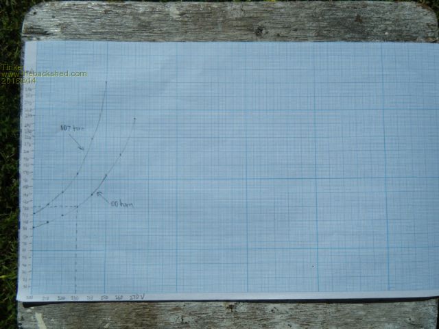
Unfortunately the pic did not turn out too sharp. I took it outside in the sunshine as at macro setting with a flash the blue graph lines washed out ccompletely. The X axis represents the voltage, from 200V to 270V. The Y axis represents the current (in mA) from zero to 300mA The lower graph is from the 100 turns. The upper graph is with 7 added turns. Your comments are appreciated. Klaus |
||||
oztules Guru Joined: 26/07/2007 Location: AustraliaPosts: 1686 |
"Out of curiosity I tested what would happen if more turns were added. An offcut of wire gave me 7 turns, these were just roughly wound around the core for the test. The extra 7 turns greatly increased the magnetising current, see the graph. So its not better to have more turns, there is indeed an optimal number. Something else new I learned from you. " I don't understand this at all... it should not have happened, it should have gone down, not up.. more turns should always be better for lower current as it is the amp-turns that give the magnetising... more turns= less amps... So I can't explain the results.... unless the turns were running the wrong way perhaps.. other than that I have no idea I'm afraid. The bottom lines tell us we are close to perfect for 230v operation... we are still basically linear, but as we go higher voltage we start to become less linear, so we have the best combination of wire resistance and mass and current. Less turns would have been a disadvantage ( higher magnetising current), more turns would be more resistive losses under high load, so we are in the sweet spot.... that was what I was alluding to. Sadly.. again....the second ( top )curve makes no sense to me, unless you had a drop in frequency, or the 7 turns were counter wound, so behaving as 93 turns not 107 turns... I have no idea.... no explanation... I'm sorry. Glad you got a working inverter out of all of this. What sort of power have you seen out of it, and does it work as you had hoped. Your workmanship is enviable. edit..... Where in the circuit did you measure the current.. input to the variac, or input to the transformer secondary..... wondering if the variac introduced losses if it is auto tranformer type, rather than resistor. If you measured the input to the transformer winding only, then variac losses would not be counted... and I am still lost. ............oztules Village idiot...or... just another hack out of his depth |
||||
| Tinker Guru Joined: 07/11/2007 Location: AustraliaPosts: 1904 |
Hi oztules, The current was measured after the variac, at the input to the toroid winding. But you may have a point with the counter direction winding. I'll re check that and let you know - its quite possible I got confused, happens frequently I'm afraid 
I'm glad to know my 100 turn decision was the right one, I'll leave that as it is and let you know the result of the extra temporary turns re test. Your comment: "Glad you got a working inverter out of all of this. What sort of power have you seen out of it, and does it work as you had hoped. " Well, this one is still in progress, its going to be an upgrade from the single core toroid I started last year and which now powers my house's GPO's. It did almost 2000KWh by now, with no problem. But the fans runs often as the power jack modules inside the original Aerosharp enclosure take up a lot of room and restrict natural ventilation. So I hope the double stack version in progress will solve that, especially with the big Aerosharp heatsink outside a bigger enclosure. Klaus |
||||
Madness Guru Joined: 08/10/2011 Location: AustraliaPosts: 2498 |
Mine ended with 98 turns on the secondary, I measured the current as you have done on my completed torroid and it draw 140ma according to my meter. However I don't have a variac, I just used a 2400 watt fan heater as a resistor in series. There are only 10 types of people in the world: those who understand binary, and those who don't. |
||||
| Tinker Guru Joined: 07/11/2007 Location: AustraliaPosts: 1904 |
OK, I admit it, I goofed   
Looking at the picture of the end of the winding you can see how. 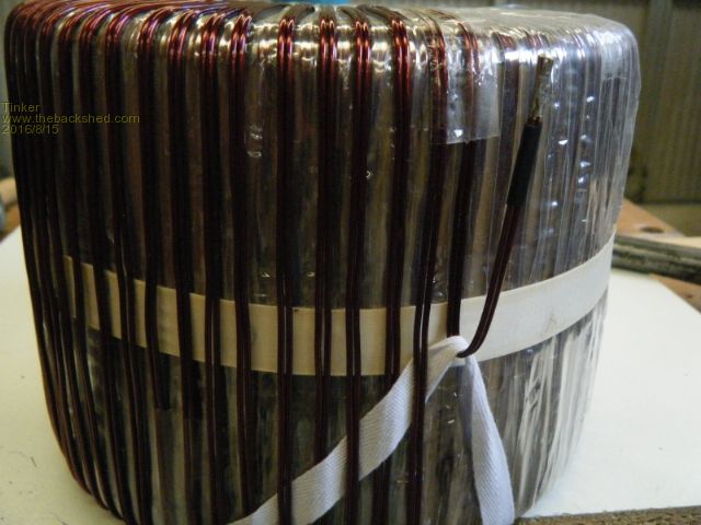
I should have known from the current that I'd connected the extra turns backward. My excuse is that it has been a very long time since I learned about transformers during my apprenticeship and have not dealt with them since until recently. Anyway, I conducted a series of tests with additional turns and drew graphs to show what happens to the magnetising current. 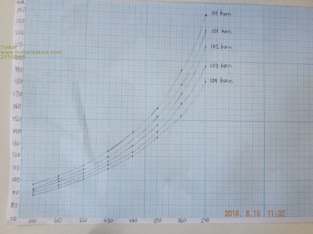
So I conclude that for my size double stack core and for a 230V secondary 100 turns are just OK. 102 turns would be better but not by much unless one wanted a 240V secondary. I hope that graph helps some inverter builders without a variac. But these cores do differ somewhat in size, the single core inverter I built previously only had 190mm OD, the ones above were 203mmOD. All were salvaged from Aerosharp 3Kw inverters. Klaus |
||||
oztules Guru Joined: 26/07/2007 Location: AustraliaPosts: 1686 |
Thats better, makes perfect sense now..... whew.. thought I needed to relearn everything. Yes it is about right with 100 turns. The 20ma saved by going to 104 is probably false in the end, as the idle current is paid only once, and does not increase with load... the R loss does, so thats the one to keep an eye on really... as well as getting near saturation, without over doing thing... ie sweet spot  ( 4 turns is 2% of your losses when you put the foot down) ( 4 turns is 2% of your losses when you put the foot down)
One could argue both ways I guess. It shows the rule of thumb is only a bit conservative, not a lot, so thats good too.... well done. I go for 230 not 240 mostly... just to relieve the unit a little bit from big resitive loads.. ie they work almost as well, but you may shed a few hundred watts at 10v lower for a 3kw element.. the batteries will like the lower loads ..........oztules Village idiot...or... just another hack out of his depth |
||||
| Tinker Guru Joined: 07/11/2007 Location: AustraliaPosts: 1904 |
A little bit more progress.... I believe I can do a better job with anything if I'm in a comfortable position to do it. So, here is how I wind my toroid core: 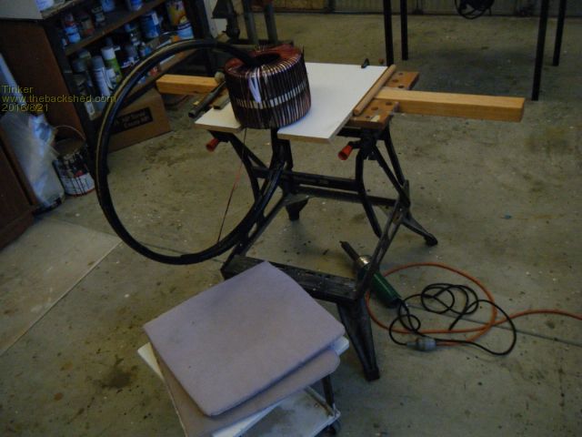
You can see I do that sitting down on that little stool on castors. With the core oriented this way there is no heavy lifting involved, just sliding it round over the work table cutout. My winding two in hand at once idea worked better than I had hoped. I would certainly do it that way again should I be mad enough to start another inverter  . .
The poly tubes have a big advantage over the bicycle rim idea that has been mentioned. The wires are *inside* the tubes and so cannot jump out if one lets the wire tension off. With the fishing reel thing I used on my single core I always had to stick a bit of masking tape over the rim the keep the wire on. Not so with the "circular shuttle". I just pull out sufficient wire for a turn, complete it, tension it, pull out more wire, and so on. The process is quite fast once a routine is worked out and, since the wires proceed two by two on the outside of the core, doing that with two separate wires (for two in hand) makes a lot of sense. I wound one complete circle around the core, which turned out to be 76 turns on the first 2 in hand layer and 74 turns on the second. I stopped winding after the first layer and epoxied the inside (hole) wires plus the top & bottom. 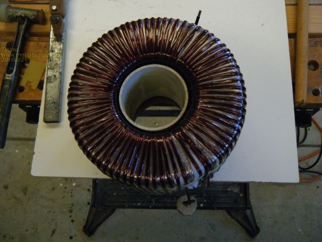
To push the wires in the hole out against the core an offcut of PVC pipe was used. This can be easily adjusted to size by cutting out a small segment. That pipe has to be waxed first, to stop the epoxy sticking to it. Only just enough epoxy to wick down halfway was brushed into the little 'well'. Once the epoxy had gone off I knocked the PVC pipe down until it formed a 'well on the other side, turned the core over and epoxied that side. Then the layer was covered with the mylar tape. After this the remaining wire was spliced on to wind 24 more turns on (first winding)to complete it. The epoxying was repeated after each layer. So I ended up with two identical winding's, each two in hand of 1.8mm diameter wire. I tested after each stage for short turns, much easier to correct then as when the core is completely wound. The epoxying locked the wires in the hole tight but those on the outside were still too lose for my liking. It is quite difficult to tension the wire there sufficiently, this would be easier if the core's outside was a little barrel shaped. So I would suggest to wind two or three layers of epoxied 50mm glass scrim tape around the join between the two cores, to introduce a little barrel shape before starting the winding process. I used a different solution, which can be done afterward, and it produced a very solid outer layer. 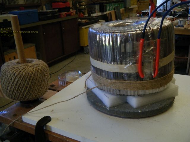
Just cheap natural fiber twine (jute) was used, it works like a boa constrictor on the wires under the mylar tape. It does not slip as synthetic twine would and soaks up the epoxy very well. I quickly found that leather gloves were a good idea, even so I got a little blister from that work. But it was worth it IMO. The finished job. 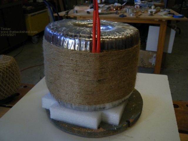
And now epoxied. 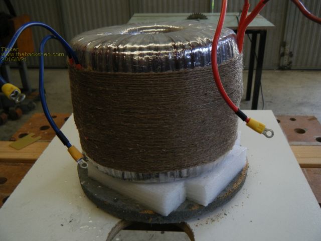
Another test, to see if that twine belt made a difference, followed. My twin stack core had a faint hum when I tested the two winding's if they had an identical voltage, before the twine was wound on. So I connected one winding to 230V and a 2.4Kw kettle to the other. I could not detect any hum, quiet as a mouse. This made me happy as the single core inverter I made last year does hum a bit (but not annoyingly)if it has some load on it. Next came the foil static screen. I had two of these copper foil strips, one from each donor toroid. Both were needed as one strip barely made it halfway round the toroid, if wound on with a minimal overlap. 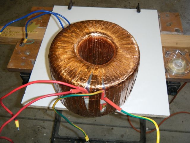
Again I tested for shorted turns, it would be hard to spot damage to that flimsy foil tape otherwise. Also, tested if the two foil runs had no connection to each other. They will terminate at a common earth point. More mylar tape and my double stack toroid was now ready for the primary winding. 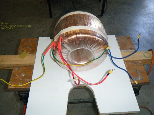
This will commence as soon as I had sourced a suitable wire. Before I end this post a hint or two: If using 1.8mm wire on a 100x203x70 core, twin stack, then each layer requires about 600 gram of wire. Winding just that much onto the 'shuttle' leaves just a little wire to take off (which has to be done to remove the 'circular shuttle' from the core), to make room for the mylar tape job. 200 gram is enough to wind the remaining 24 or 26 turns - for a 100 turn secondary. The poly tubes got quite tatty by the time I finished with them and were held together just by the gaffa tape. I since experimented with superglue and it does stick that tube, I wiped it first with acetone. Supergluing it together would make a much better double barrel 'circular shuttle', in addition to the gaffa tape. Cut a V notch at each start & end of the slit in the tubes, to allow the wire easily transit the section where the tubes meet. The slits are unlikely to align 100%. I used 600mm diameter for the 'circular shuttle' but 800mm would be better. My shuttle was a little tight towards the end of the winding process, a bigger diameter would help. But, as it is flexible, its not a job wrecker as a bicycle rim would have been. Plus, two bicycle rims would never fit side by side in the toroid hole. Klaus |
||||