|

|
Forum Index : Electronics : Building a new Inverter.
| Author | Message | ||||
oztules Guru Joined: 26/07/2007 Location: AustraliaPosts: 1686 |
The PJ can only synchronise it's 240v input to match a power source and then power loads or charge batteries ( switch dependent) or both It cannot sync the output simply... like a grid tie unit can do. If the latronics can grid tie normally ( PJ cannot), then a simple grid tie to the PJ by the latronics will work...... Otherwise leaving them seperate will be the simplest safest way of proceeding.... which works well already from the sounds of it. Wave addition of the 240v will yeild 640 volt peaks max.... nothing to bother with really in your mains circuits... if they are kept seperate then only 320v is present. However, our MEN circuits will make neutral common via the earth buss, so between actives on both circuits 640vp will appear transiently as the freq will never be identical.... still no problem that I can see with the circuits.... they will only see 320v peak... the 640v will only appear in close proximity in the fuse box, and thats not a problem either.... all designed for three phase interaction, where 590v or more is normal peak volts. ......oztules Village idiot...or... just another hack out of his depth |
||||
| gpalterpower Senior Member Joined: 19/07/2009 Location: AustraliaPosts: 175 |
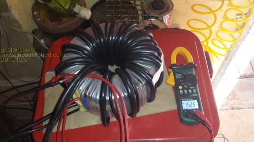
Hi all, well Ive been kinda busy, but finally got a chance to wind on the primary on the weekend. At first I was going to wind with 50mm as OZ suggested but that meant that I would have go out and purchase some more cable..... and since I nearly have half a roll here of 35mm at home I pondererd on the idea of winding 35 and 10mm side by side. Now I know thats not 50 mm but it probably is close enough for the job. In theory it should work but I thought id run it by you guys and see what you think. Is it unbalanced? I powered up the secondary with 240 thru a 60w globe and checked the voltage at the primary end. 15.25v Is this the right voltage we are looking for? 
Also been checking ebay for the main board and controller but can never seem to get the two at the same time ...one or the other is out of stock ( 8000w 24/220) and Id rather have them both delivered at the same time. At this rate it will be way after christmas before I recieve them. Just waiting on a reply msg from PJ. Marcus ps. Glen, Hope you dont mind adding my inverter questions to your thread. I start a new one if you desire. if it aint broke dont fix it!! |
||||
| yahoo2 Guru Joined: 05/04/2011 Location: AustraliaPosts: 1166 |
cross section area 35mm2+35mm2=2450=49.4mm2 50mm2=2500 35mm2+10mm2=1325=36.4mm2 so 2 in hand 35mm2 is a good option I am sure someone will correct me if I am wrong the traditional calculation would be 24v/1.41 = 17 volts the actual inverter calculation allows for voltage sag and the PWM closed loop current control. so 250v @ 16 to 1 turn ratio = 15.625 volts I guess inputting 240v on the secondary would give 15 volts on the primary so you are pretty close to the mark! I'm confused, no wait... maybe I'm not... |
||||
oztules Guru Joined: 26/07/2007 Location: AustraliaPosts: 1686 |
I agree with Yahoo2. For 24v, even 3kw (which mine runs or 2-3 hrs a day at time in the mornings, is 120 amps or more, for me it is ony 60 amps, so not a big deal for 35mmsq.. @48 v ) As you have plenty of 35mm wire, 2 in hand is the go... only 3-4 meters per winding too.... so not a nightmare to do. Your boards will run 3kw-4kw indefinately, so you want the tranny to run happy too, and you want as small a sag as possible when running hard, or your fets work harder than they need. ...........oztules Village idiot...or... just another hack out of his depth |
||||
| yahoo2 Guru Joined: 05/04/2011 Location: AustraliaPosts: 1166 |
I should have put some extra detail as explanation in my post for the calculation method for those like me, who forget. My area calculation is square the wire sizes then add them together and square root the total. the 1.41 figure I plucked from nowhere to get the 17 volts AC is a rough estimation of the rmsVOLTS (area under the curve)of converting DC to AC Sine wave at mains frequency. in the third paragraph 250 volts is an allowance under heavy load with the inverter running at full throttle. under light loads when the batteries are getting close to full charge, say 29 volts, the inverter controller is adjusting the output voltage back 4% for the sag allowance and about 18 - 25% for the variation in battery voltage. in the 4th paragraph we are just checking that the transformer ratio of 16 to 1 for a 24 volt system is correct by comparing the measurement on the primary to a known/measured voltage on the secondary, in this case mains electricity (i am presuming it is at 240 volts). that about covers it Cheers! I'm confused, no wait... maybe I'm not... |
||||
| gpalterpower Senior Member Joined: 19/07/2009 Location: AustraliaPosts: 175 |
Thanks guys, In not sure if I can fit in 2 in hand of 35mm2 neatly. I tried just a single run of 35mm and I was about 3/4 away around the inner hole, so thats why I added the 10mm2 which fits ok with a bit of space left over. I also have some 16mm2 as well, so I could remove the 10mm and replace it with the 16mm, ending up with a neat wind and no overlapping. Seems like my calcs were wrong. I always assumed that in my case 35mm2 and 10mm2 would add up to 45mm2, or 35mm2 and 35mm2 would equal 70mm2 . Think I need to go back to school!! Could there be a problem by having 2 different sized cables?.....OR...... am I better to have a 2 in hand 35mm that dosent look so preety, but works? I probably should of mentioned the voltage input yesterday, so I did some rechecking. Mains voltage thru a 60w lamp to the secondary is 235v and the output on the primary 15.56v. Is that close to the money? Thanks Marcus if it aint broke dont fix it!! |
||||
oztules Guru Joined: 26/07/2007 Location: AustraliaPosts: 1686 |
Marcus, I also find that 2 in hand 35mms2 is in fact 70mmsq...cross section. Given that 35mmsq will handle 140 amps ok, twice would give you some room, as your peaks will exceed 200amps on may occasions I suspect. 2 in hand will get you some clear space of 300 amps and more short term. It does not need to be neat... nice but not necessary, the wire needs to go through the hole... and thats it. Perhaps wind one layer then the other, length will be different, but it is only turns of wire going in the hole that counts. There will be a slight phase change with the two different length wires, but it is academic, not practical in nature over this length ( different in single phase inducton motors though)... this should be fairly neat I think. Voltage is close enough. ..............oztules Village idiot...or... just another hack out of his depth |
||||
| yahoo2 Guru Joined: 05/04/2011 Location: AustraliaPosts: 1166 |
my bad, I am so used to dealing with wire diameter I had a brain fade. I'm confused, no wait... maybe I'm not... |
||||
| gpalterpower Senior Member Joined: 19/07/2009 Location: AustraliaPosts: 175 |
Yahoo... Not a problem. I get those brain fades on a daily basis. if it aint broke dont fix it!! |
||||
| Tinker Guru Joined: 07/11/2007 Location: AustraliaPosts: 1904 |
I just bread boarded this circuit for a 24V fan (got those at 1/2 price) and it works well with just a minor change. For those who are interested: I replaced the zener diode with a 6V2 type. Used a 10K NTC thermistor from Altronics (looks like the one on the PJ heat sink). I used a LM 318 OP Amp and a 3055V mosfet - had both of these on hand. I adjusted the pots so that the fan stopped at room temperature (~27 deg C). Fitted a small heatsink to the NTC thermistor and warmed it between my fingers so the fan started up - did minor pot adjustments to get it do that repeatedly. Waited until fan stopped (had the thermistor heatsink in the fan's air stream), then held the soldering iron to the heat sink, the fan started up flat out - removed soldering iron and the fan stopped after a while. I measured the feedback (pot + 10K resistor) and the total was 27K. Replaced feedback pot & 10K with 27K resistor and the circuit worked fine. Thanks again Glenn for posting the circuit, I will now lay out a small PCB for this. Klaus |
||||
| mason Regular Member Joined: 07/11/2015 Location: CanadaPosts: 86 |
Happy New Year Just wondering if anyone could help me out, I started to make one of these inverters, had everything ready to go and stupid me incidentally had the outputs on the control board shorted, one of the mosboards started on fire,  lol , the control board looks fine but I'm sure there are some components that needs replacing. lol , the control board looks fine but I'm sure there are some components that needs replacing.
Should I start from scratch or try to repair these boards. thx Billy |
||||
| Gizmo Admin Group Joined: 05/06/2004 Location: AustraliaPosts: 5078 |
Hi Billy. Control board or the big MOSFET board? If its the control board, they are fairly cheap, might be easier to buy a new one. Or you could fault find the damaged board and replace parts as you go. Glenn The best time to plant a tree was twenty years ago, the second best time is right now. JAQ |
||||
oztules Guru Joined: 26/07/2007 Location: AustraliaPosts: 1686 |
fix the mosfet board... all simple stuff there. The control card is fairly cheap, and complex.... buy another one. Not sure how you blew it though... if ac got to the chip it is finished anyway. If it is only the drivers.. then fairly easy to fix, but i fear it is deeper than that. ......oztules Village idiot...or... just another hack out of his depth |
||||
| mason Regular Member Joined: 07/11/2015 Location: CanadaPosts: 86 |
Thanks guys, Gizmo, yeah the mosfet board blew up and started on fire, but not sure if the control board is damaged. oztules, I think your right and the ac got to it. I think I'LL start over and make sure i'm wearing my glasses this time. Billy |
||||
| mason Regular Member Joined: 07/11/2015 Location: CanadaPosts: 86 |
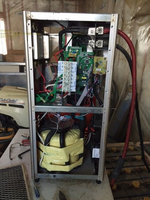
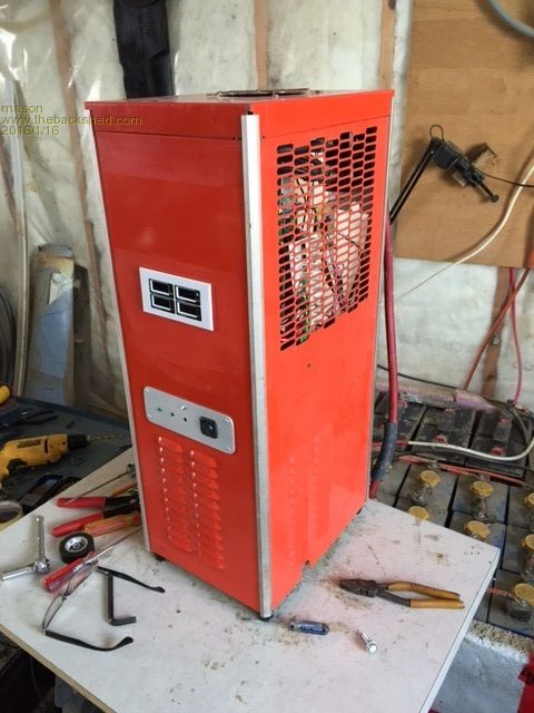
Well ordered new boards and everything is working fine, Just want to thank Oztules and Clockman for posting all their work. My Oz-Inverter is 24volts 10000watt- 220 60hz split phase, I used a old air dryer encloser, the transformer weighs 75 lbs so I thought this floor mount enclosure would work the best. Billy 

|
||||
oztules Guru Joined: 26/07/2007 Location: AustraliaPosts: 1686 |
Good tall enclosure. It will help a great deal in getting the heat out of it. I'm really liking that enclosure.. and these inverters generally... tough as nails. Nice big transformer too. ............oztules Village idiot...or... just another hack out of his depth |
||||
| Clockmanfr Guru Joined: 23/10/2015 Location: FrancePosts: 429 |
Nice Mason, I am doing my No2 'BigOzInverter' at present, yes I have the disease. I now find that good enclosures are reasonably priced, here is one that is ideal and optimal for good cooling. (I have no connection with these folk). The base and top plates are just right for grilling, the chassis plate is good, and the case is well made out of thick steel. Made by Europa, 600mm high, 500mm wide and 300mm deep. http://www.fastlec.co.uk/600-x-500-x-300mm-ip65-steel-enclosure And these folk will send to Europe at a reasonable cost. Needs a support bracket when mounting to a solid wall. Everything is possible, just give me time. 3 HughP's 3.7m Wind T's (14 years). 5kW PV on 3 Trackers, (10 yrs). 21kW PV AC coupled SH GTI's. OzInverter created Grid. 1300ah 48v. |
||||
| mason Regular Member Joined: 07/11/2015 Location: CanadaPosts: 86 |
I'm from Canada, and a case like that starts at 300usd here, I priced one that was 21"w x 24"h x 10"d my price was 595 cnd crazy. I'm looking forward to seeing your next build , also the arduino uno set up. Billy |
||||
Madness Guru Joined: 08/10/2011 Location: AustraliaPosts: 2498 |
Hi Oztules, I have been searching through the various forums about this inverter project and am very interested in building one. One thing I have been trying to find out is how well it works as a charger and in particular switching from inverter to charger when a generator is connected. (I am using a 8kva Lister Stamford generator) There is mention of major problems switching at other than the peak of the wave, is that still the case? I ideally I would like to be able to have the generator auto start if the battery voltage gets too low as I can do with the Trace SW4845E I am using at present. I understand there is no smarts in the inverter design to do this but it would be quite easy to setup that part with an Arduino. Thanks Gary There are only 10 types of people in the world: those who understand binary, and those who don't. |
||||
oztules Guru Joined: 26/07/2007 Location: AustraliaPosts: 1686 |
I can't sensibly answer that. Long ago I decided to use them as a inverter only ( unless grid tied, then it is a charger). The recovery from switching off the grid to it, may have been solved in later units, but I have no knowledge of success or otherwise. It is just as cheap and simple to buy a few of those meanwell power supplies and just drive the bank from those... maybe $30 each, and for 15A@28v is fine when you double them up. Other folks may have had some success, but I am not game to try anymore... plus I have migrated across to the 8010 chip and drivers, as they run the unit cooler from tests so far... ie 10 mins of 5799 watts this morning went to 38C and no further with a single slow fan.... truly amazing efficiency from the looks of it... more testing to go. Running this at the moment. 2016-06-07_064438_80109d.pdf Village idiot...or... just another hack out of his depth |
||||