|

|
Forum Index : Windmills : My new mill
| Author | Message | ||||
| VK4AYQ Guru Joined: 02/12/2009 Location: AustraliaPosts: 2539 |
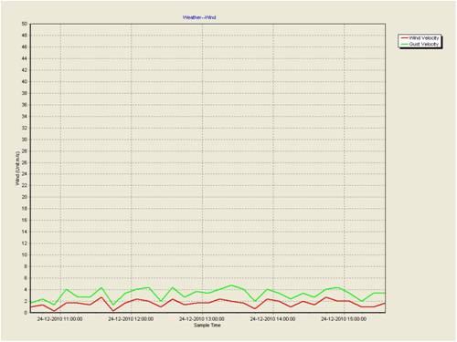
Hi All The rain stopped for a few hours today, so I decided to fit the boost modules to the mills to get an idea how they would perform. The results where quite pleasing, I had steady slow wind speeds as shown in the graph below. 
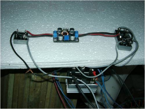
The boost modules are set for 26.5 volts DC output and work from 5 Volts AC input to 32 volts AC. They cut in at four volts AC, as thats enough power to get the boost circuit activated and 75 ma output into the batteries at cut in. At 10 volts AC the module delivers 1 amp at 26.5 volts at 12 volts AC it delivers 2 amps at 26.5 volts and 15 volts it peaks at 3 amps, at this point the GTI is cutting in and sync's so the mill is loaded a bit heavier. When the load voltage goes above 26.6 volts it shuts down During the testing at the wind speeds shown the Boost module went from 100ma to 3 amps Once it got to that level the doubler circuit started to come in with 1 + amps so there wasn't any appreciable gain in amps from the module. As its rated at 3.5 amps continuous or 5 amps intermittent with current limiting at that, it is working well within it's specifications. If the batteries where to drop below 24 volts it would max out and and current limit. The arrangement of the module is a separate 3 phase bridge to feed it and a single bridge on the DC output to isolate it from back feeds from the battery or other charging circuits. Seems to work well and no smoke so far. 

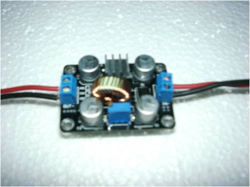
As you can see it is quite small about the size of a matchbox. cost around $15 on fleabay, which worked out less than the cost of the components, not to mention the circuit board, I could have built one but my eyesight isnt to good in these little things. All the best Bob Foolin Around |
||||
| VK4AYQ Guru Joined: 02/12/2009 Location: AustraliaPosts: 2539 |
Hi All I have been doing experiments to get the best low speed power out of the mill as it does a lot of spinning around without putting any power into the battery, so here is a mud map circuit as to what I have been fooling around with as documented in the previous post. After reading the post I decided that it was a bit difficult to understand and a simple circuit would help. Sorry for the poor quality of the diagram as I had to do it by hand after playing with a circuit drawing program with no success,I had hoped to make it look good and clear but, my well below average computer skills let me down, and there wasn't any grand kids within Cooeeee, never around when you need them. Hope you can make some sense of it. All the best Bob Foolin Around |
||||
| Tinker Guru Joined: 07/11/2007 Location: AustraliaPosts: 1904 |
Hi Bob, That 'boost module' you mention has me intrigued. Do you have a detailed type # so I could find it easy on e-bay? I'm asking because I'm known to get totally side tracked perusing e-bay offers and spend too much time browsing there 
Thanks. Klaus |
||||
| isaiah Guru Joined: 25/12/2009 Location: United StatesPosts: 303 |
Bob. With all those amp meters in circuit and all those other electronic bits do you ever get any amp's out the other end? '  ' '
There will be amp loss at each one of those meters,as they have small wire in them. Are you using Hi Performance Amperage wire for the rest of the wiring? The other day I was hooking my mini mill to my battery bank and the wire I was using was a extension cord and was already hooked to the battery end and when I went up to the mill to hook it I noticed that I bumped the Wires together there wasn't much of a spark at all!! So I went over to Bubs and got a 60 amp amp meter and took it over and hooked it to the extension cord in a dead short and it showed about 15 amps.!!! '  ' '
I went back over to Bubs and got some wire he has there and cut a length the same as the extension cord and took the same 60 amp meter and hooked it up short test with that piece of wire and it pegged the amp meter out. So then we cut another length the same and hooked it to the Battery bank and tested it the same way with that 60 amp meter and got the same results, it pegged the amp meter!! We hooked the mill up but so far we haven't got enough wind to talk about. '  ' '
You have to think of electricity as water, If you keep putting joints and gadgets in the garden hose you wont get much out the other end. Maybe just pour some hi amperage volts in a good plastic or rubber bucket and carry them over to the battery bank. '  ' 'URL=http://www.motherearthnews.com/Renewable-Energy/1973-11- 01/The-Plowboy-Interview.aspx>The Plowboy Interview[/URL> |
||||
| VK4AYQ Guru Joined: 02/12/2009 Location: AustraliaPosts: 2539 |
Hi Klaus I will post the details for you later today when the rain eases as the satellite connection is snail pace when wet. Bob Foolin Around |
||||
| VK4AYQ Guru Joined: 02/12/2009 Location: AustraliaPosts: 2539 |
Hi Klaus This is a cut and paste from fleabay, the unit is a current limiting device, there are some available with a LM2577 but they don't have current limiting, they are a bit cheaper. LM2587 DC-DC Step-Up Module Input 3-24V Output 4-35V Item condition: Brand New Quantity: More than 10 available Price: US $14.50 Approximately AU $14.44 Buy anotherBuy another Add to list Postage: FREE postage Standard Int'l Flat Rate Postage | See all details Estimated delivery time varies for items posted from an international location. Seller info 24x7diy ( 641) 99.1% Positive feedback Ask a question Save this seller See other items Visit store: 24x7 DIY Other item info Item number: 260684027071 Item location: Faridabad, India Posts to: N. and S. America, Europe, Asia, Australia History: 19 sold 
2010-12-26_103356_LM2587.pdf The circuit in the booster supplied isnt the same as in the info sheet they have designed a circuit to do the job. All the best Bob Foolin Around |
||||
| VK4AYQ Guru Joined: 02/12/2009 Location: AustraliaPosts: 2539 |
Hi Charlie The circuit is a bit over metered but without a meter on each unit it isnt possible to see what is happening with each part at the same time. Yes there is losses but that means when it is hard wired it will perform slightly better, bonus. Wire losses are very small as the doubler peaks at 3 amps and the same for the booster, the main rectifier is connected with 3.2 mm wire so it is a bit light when full power, but provides a bit of a load buffer on the mill by a bit of circuit resistance, when it is all hardwired there will be less losses, but for now just testing with a hay wire setup. 
All the best Bob Foolin Around |
||||
Downwind Guru Joined: 09/09/2009 Location: AustraliaPosts: 2333 |
Ebay link for the above item. http://cgi.ebay.com.au/ws/eBayISAPI.dll?ViewItem&item=260684 027071&ru=http%3A%2F%2Fshop.ebay.com.au%3A80%2F%3F_from%3DR4 0%26_npmv%3D3%26_trksid%3Dm570%26_nkw%3D260684027071%2B%26_f vi%3D1&_rdc=1 Pete. Sometimes it just works |
||||
| VK4AYQ Guru Joined: 02/12/2009 Location: AustraliaPosts: 2539 |
Hi Pete Thanks for doing the link for that one day I will have to learn how to do it. Its a neat little doover and I think has the ability to extract the last few milliamps from the mill. All the best Bob Foolin Around |
||||
| Tinker Guru Joined: 07/11/2007 Location: AustraliaPosts: 1904 |
Thanks Bob for the info and thanks Pete for the link - I have ordered one now. One can never have enough gadgets  , besides, the geared up VAWT I have can do with any help available to get an earlier cutin to my 24V battery bank. I do have the capacitor doubler arrangement but that moves the needle of the 0-5A output meter off the zero peg only in the gusts. The mill is turning most of the time the wind blows. , besides, the geared up VAWT I have can do with any help available to get an earlier cutin to my 24V battery bank. I do have the capacitor doubler arrangement but that moves the needle of the 0-5A output meter off the zero peg only in the gusts. The mill is turning most of the time the wind blows.
Bob, studying your hand drawn circuit I notice you have placed what appears to be another rectifier at the output of the booster module. Could you confirm it is indeed a bridge rectifier and if so why rectify the DC output from the module again? edit, re reading the original description of your set up I see it is for isolation. If the battery bank is always connected then the gadget would never see more than battery terminal voltage. I would put a small fuse (5A) there instead. BTW, the battery volt meter is best connected directly to the battery terminals, not ahead of the Amp meter. Cheers Klaus Klaus |
||||
Downwind Guru Joined: 09/09/2009 Location: AustraliaPosts: 2333 |
[quote]one day I will have to learn how to do it.[/quote] Its easy Bob. See photo.......... Click on the icon in the circle. You might get a bar asking you to allow scripting at the top of screen, click on the bar and then click on allow scripting in the dropdown menu. Click on the icon in the circle AGAIN, this time you will get a popup window. Enter the link address (copy and paste) into the box, click ok. Then enter the address again in the next box, click ok. Thats it ...job done. Pete. Sometimes it just works |
||||
Downwind Guru Joined: 09/09/2009 Location: AustraliaPosts: 2333 |
One is guessing the post rectifier is only there as a blocking diode to prevent feed back, and any single 3 amp diode would do, but Bob used a bridge module for simplicity of use. The boost module only looks to be 90% efficient so has a reasonable loss, but 90% of what you didnt get in the first place is still better than what you had. Pete. Sometimes it just works |
||||
| VK4AYQ Guru Joined: 02/12/2009 Location: AustraliaPosts: 2539 |
Hi Pete Thanks for that now i can see what I was doing wrong. Hope to get it right next time. Hi Klaus The setup is a bit haywire to to allow testing for final setup, the reason for the extra diode bridge is to isolate the booster from both directions, also to stop a small reverse current, that I think is caused by the regulator voltage divider. It should work on your VAWT providing it is doing over 10 volts AC when spinning as that seems to be when the unit starts to produce some usefull current, it works below that but only makes a few milliamps. I have some 5 amp and 15 amp circuit breakers coming as I dont like changing fuses. I also have a 16 amp unit coming and will see if it can replace the capp doubler as well on my next mill, time will tell. The big bridges are a bit of an overkill but cheaper than smaller bridges. All the best Bob Foolin Around |
||||
| isaiah Guru Joined: 25/12/2009 Location: United StatesPosts: 303 |
Bob, That module you are changing dc to ac to activate the module then it changes back to dc.? Could it be wired to run on all dc?. I may think about one for my mill to boost up some of the below cut it to use full. We still haven't had much good wind yet the mill has hit cut in but not for long then losses it. Bub's gage showed 3 mph wind speed. Charlie URL=http://www.motherearthnews.com/Renewable-Energy/1973-11- 01/The-Plowboy-Interview.aspx>The Plowboy Interview[/URL> |
||||
| VK4AYQ Guru Joined: 02/12/2009 Location: AustraliaPosts: 2539 |
Hi Charlie The reason for the 3 phase bridge in front of the boost module is that if you connect to the existing dc then it causes a loop through the module and it wont charge, as the voltage has to be lower on the feed in side than the regulated output side for it to work. The input voltage is DC as it has the rectifier in front of it, which in effect is direct across the AC from the generator. There needs to be around 10 volts AC from the mill to get it to work so check your output from the mill, it will work lower than that but for a very small current, mine starts at 5 volts AC but only delivers 100 ma. All the best Bob Foolin Around |
||||
| VK4AYQ Guru Joined: 02/12/2009 Location: AustraliaPosts: 2539 |
Hi All Wind died down today so I took the opportunity to climb on the roof as the ground is still to wet to do much mowing. I pulled the mill down for a check over today after the recent high wind events, as I was a bit nervous about some of the comments I got. All was well inside the mill with no signs of heating or poleing on the magnets, the bearings have run in nicely and no sign of water damage from the recent 11 plus inches of rain, so all was above expectation. I decided to set up the Stator in the lathe for a checkup and reduced the diameter by .010 thou this will take the magnet to pole clearance to .020 as I felt it was a bit close at .010 as the coat of paint I applied to the magnets and the stator where rubbing in one spot, this was caused by a slight out of round on the stator, now its perfectly round it should get rid of the growl it was getting at low speed. I think this was caused by the varying clearance from the coils to the magnets, thats my theory anyway time will prove me wrong. I am going to experiment with some different furling angles, on Phill's suggestion I tried to furl by hand, and it is extremely hard to do. It has 12.5 degrees lay back and 2 degrees side angle. I think the lay back is too much, reading an article on furling for this size mill they suggest a sum of angles between 7 and 9 degrees depending on the offset of the input shaft, for a furl of 15 ms. Anyone have any thoughts on this before I cut and shut? I am going to reduce the weight of the blades and re balance while I have got it down, so I will let you know how that goes. All the wiring is in good shape considering the amps it was making, but due to the intermittent nature of the wind the the average amps loading is low. All the best Bob Foolin Around |
||||
Downwind Guru Joined: 09/09/2009 Location: AustraliaPosts: 2333 |
[quote]Anyone have any thoughts on this before I cut and shut? [/quote] Yes i do but who listens anyway. I feel the problems you have are related to the direction your blades spin to the side the off set of the yaw bearing is in relation to this. For a mill not to furl when the tail is furling it can only mean one thing, being the way the forces are applied to the yaw bearing. With a off set the mill is duty bound to move out of the wind when the tail is no longer holding it windward. In your case this is not always correct and you must ask WHY it dont furl when the tail dose. Basically the mill rotates in the wrong direction to the yaw off set, so it drives itself into the wind (opposed to out of the wind) till it reaches a status quo of applied force to the yaw bearing.(straight line effect) You can dick around with changing angles but it will always be a band aid to the real problem. I expect to ruffle feathers over this but facts are facts and i have seen the results and also see why these mill dont furl. Fix the problem and make this mill design worth the credit it can achieve. Easy solution is to have it spin in the opposite direction. Pete. Sometimes it just works |
||||
| VK4AYQ Guru Joined: 02/12/2009 Location: AustraliaPosts: 2539 |
Hi Pete Looking from the front of the mill the offset is to the right of the yaw pivot and the blades revolve clockwise so the center of the propeller disk is to the right of the yaw pivot, causing a turning moment to the right, increasing at the square of the wind speed as the propeller loads up. This is I believe is the standard way that most articles present the furling action. As you know I am no fan of furling as I have seen more mills destroyed by violent furling actions than destroyed by over speeds. The nodding action I observed is a start to furl and then the propeller pulls back into the wind due to center of pressure changes of the disk. This is exaserpated by the blades being in a over speed situation when the furling tries to happen and thereby partly unloaded as the alternator can no longer absorb the power produced. This then is with a combination of centrifugation force and gyroscopic forces acting together to try to stabilize the disk. As you say the turning the blades the other way will will alter the resultant force 180 degrees, but the problem is the reconfiguration of the blades to rotate counter clockwise would mean new spindles, and I think the forces generated by rotation are acting up and down and not sideways. You mention that the tail furls but the mill doesn't, I think I gave you the wrong impression from my previous observations, The kicker on the end of the vane tended to start the furl, but the mill disk also started to furl and then came out of furl, as it is the mill that should furl not the tail, the tail just stays more or less with the wind and the offset on the mill furls the disk, if the force generated by turning the blades the other way helps this it would be the answer. I take your point and would like to leave the decision open for more comment. All the best Bob Foolin Around |
||||
| isaiah Guru Joined: 25/12/2009 Location: United StatesPosts: 303 |
Bob, As long as you got the mill down see if you can put the blades on backwards!! Make it turn the opposite direction as Pete states. You might look around for a ECM motor next time in town and convert that into a turbine. Mine seems to be working good.with the ecm you don't need the furrel tail!!' They start up easy and make good low wind turbines.\ The ECM Is very expensive new so you want to look for a used one and most of the time the computer brains is what goes bad and our operation we throw them away and just use the motor you can play with the wiring configurations.star, delta ,jerry URL=http://www.motherearthnews.com/Renewable-Energy/1973-11- 01/The-Plowboy-Interview.aspx>The Plowboy Interview[/URL> |
||||
| JimBo911 Senior Member Joined: 26/03/2009 Location: United StatesPosts: 262 |
Hey Pete (Ruffled Feathers) I do know in Hugh Piggotts book (A Wind Turbine Recipe Book)shows his alternators mounted to the left of yaw pivot with the blade rotation CW. (looking from the front)The blades are carved of wood and do incorporate twisting in them. This I believe is the opposite of your definition for the cause or bad furling of Bobs mill. Bob (If) I am understanding you correctly your mill wants to furl or it begins to furl but then returns to face the on coming winds. (If) this is what's happening in may be the same situation I was up against. My mill wanted to furl as it began to furl the tail moved up slightly which held it partially furled as I watched, the blade RPM continued to climb until the RPM matched the tail weight at which time the tail dropped down allowing the mill to be held directly in the on coming winds. This is what happened to me. I decreased the tail weight by decreasing the size of the tail fin. I my case I figured as the winds became stronger the tail fin need not be to large as the wind becomes stronger it packs more of a punch and will push even the smallest of tails where it will face the on coming wind direction. Try losing some weight in the tail? Just my two cents and what I have experienced. A video might be help full. Jim |
||||