
|

|
Forum Index : Electronics : Builiding of a complete 6kW PV inverter with MPPT chargers
| Author | Message | ||||
| KeepIS Guru Joined: 13/10/2014 Location: AustraliaPosts: 1679 |
Great, so it's the bootloader being hit with garbage right after a power on (reset) or a reset noise glitch on power down low voltage. This is one reason I don't want the bootloader in the Inverter Nano. The second issue is the Reset from the USB controller on the Nano, I've disabled that on one Nano currently in the Inverter, simply by removing an SMD cap near the USB controller. It means that plugging in a USB console will not reset the Inverter, and connecting to a Serial port from a Console program will also not cause a reset. I do not like the fact that the onboard USB controller has control of the Nano reset in my inverter. There is only a slight annoyance when programming from the Arduino IDE or similar program, you might have to press the reset button to start the program upload - no big deal. If you are using a small $7 programmer with the Arduino IDE to load a Hex file, that will not be affected. This is just the way I want it - others may have a different opinion, that fine. Thanks Dex for all the testing.  It's all too hard. Mike. |
||||
Revlac Guru Joined: 31/12/2016 Location: AustraliaPosts: 1021 |
Couldn't watch videos, But I can say I have never had any flashing/ pulsing on the MPPT charge controller, the little SMPS powers down nicely, where as the postage stamp size SMPS I have on the mad inverter did, might be worth checking which smps shuts off nicely, under certain conditions. Please ignore this if I'm off the beaten track somewhat.  Ah, the reprogram might be the answer.  Cheers Aaron Off The Grid |
||||
| -dex- Regular Member Joined: 11/01/2024 Location: PolandPosts: 99 |
I caught it on video. The flickering is more visible on the LCD than on the controller board. The inverter was not loaded, all MPPT chargers remained turned off. Video 3 Video 4 I tried with 10k resistor on off wire to ground, 5k, and 2.2k. Even with 2.2k a flickering are still there. Guess this is still to small load to discharge it quick. If your web-browser can't open & play video directly in a tab, you can try to download file by right clicking, but you need some program or app to play *mp4 file. My MPPTs use different power supply, showed few post earlier, and this is shutting down without any flickering thus amnesia doesn't occur even when loaded code to nano-mppt-controller and nano-lcd with bootlader. Edited 2024-06-05 05:01 by -dex- |
||||
| KeepIS Guru Joined: 13/10/2014 Location: AustraliaPosts: 1679 |
Looked at both videos, slight backlight flicker matches the +5 supply LED. Trying to discharge the cap bank with resistance is not going to make any difference, the cap bank is below 12v when this happens. It can be either 12v or 5v regulators and as mentioned in other conversations, we are using different +5v regulators. My 12V regulator is a 1A version. +5v is an MP 1548-PSU-01, the amount of slight flickering I see is unlikely to cause any issue with the Nano or inverter, the RX & TX LEDs are not flashing which is good. Under these conditions, the LCD-Nano should not get corrupted, as I said, I have never had this, and mine have been running under very adverse conditions with more power cycles then I can count. I know you were absolutely having trouble with this, and it looks like the fix we came up with has worked. So I will remove the bootloader from LCD and Inverter Nano, as stated in my last post, and stop the USB controller from driving the Nano Reset - Both are simple 3 second mods. In many posts, and in my old thread or correspondence, I have noted that 5v SMPS regulators have a slightly pulsed output below regulation on fading DC input, so this is nothing new from my perspective. It was the flashing RX, TX LEDs that was my main focus, but again, not apparent here. . Edited 2024-06-05 09:11 by KeepIS It's all too hard. Mike. |
||||
| wiseguy Guru Joined: 21/06/2018 Location: AustraliaPosts: 1156 |
Not sure if I have good news or bad news but I KNOW what is causing the LCD code failures that Dex is having. Here is a picture of my crashed display - it took me all of 5 minutes to nail the cause. 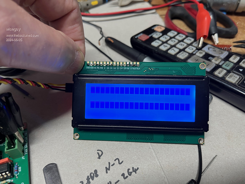 I connected up a controller and an LCD nothing else, then I put a 150R resistor on the + input lead. And set my power supply to about 6.6V in - I also monitored the controllers 5V line which was about 1.8V when the crap hit the fan. As I toggled the input voltage up in 10mV steps I got to a point where the Nano LED just turned on dimly, as I toggled up and down in a few 10mV steps bingo the TX LED on the Nano suddenly flickered busy and then when I applied 16V my display came up with black blocks that could not be cleared. I believe I was right in my assumption that at low voltages where logic etc doesn't behave well could be causing the issue. Despite protests that you doubted whether my theory was right and you categorically stated that a resistor to continue to discharge the Caps instead of allowing them to spring to life briefly could not possibly help I beg to differ. This was occurring below 7V in. I probably should be getting used to put downs but I don't like being shunted off track especially in the WRONG direction. The whole environment of this saga as it unfolded has annoyed me somewhat. If others are asking for help and I take up my time and effort to give the best response I can come up with, by all means have a different opinion, just prove yours right or mine wrong before going public maybe. When I have a clearer head I will try to come up with a cure but happy for anyone else to take it on. Edited 2024-06-05 15:36 by wiseguy If at first you dont succeed, I suggest you avoid sky diving.... Cheers Mike |
||||
| KeepIS Guru Joined: 13/10/2014 Location: AustraliaPosts: 1679 |
Mike your power supplies might be different to mine ??? Love your reply  I am saying that trying to discharge 40,000uF with a resistor (as was suggested) is not going to work. I'm basing my comments on my Inverter and what I am seeing. I' wondering exactly what value of resistor are you planning to use to drop 48V @ 40,000uf and still pull the caps down quickly at 12v. If we stop talking about the Massive cap bank and talk about loading the 12volt 5v output rail to quickly discharge the C27 100uf, then that is a different story and will work. However - all this proves is that my original fault finding fixed the LCD problem. And this still does not "APPEAR" to be causing the Nano in the Controller any problems. My Test Setup: No Nano in the socket - No Solar. NOTE !!! Testing with ONLY a 14v supply. The results of my Controller - 14V input, some capacitance on the output of the 14v supply: The current is low and 100uf on the 5V output gives a +5V decay of over a second. It might be the 12V regulator, but it's interesting that the switching waveform only shows up right when the +5v voltage drops, could be back feeding through the 12v reg? OR feeding through the 5v regulator. Sawtooth frequency varies from 139Hz to 67Hz as it falls. EDIT The 1 second fall on the 5v output may still be influenced by the 12v regulator producing output all the way down to 2v? either way a small bit of bleed on the 5v might fix it. I'll try later this evening. 12V reg output: 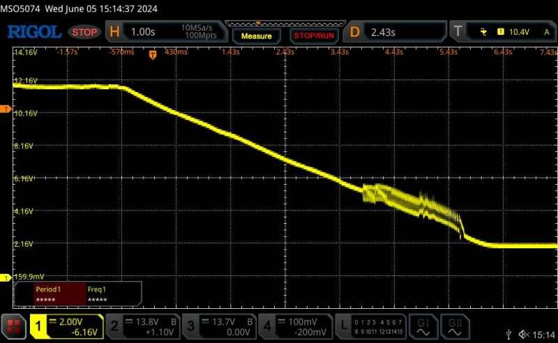 5V reg output: 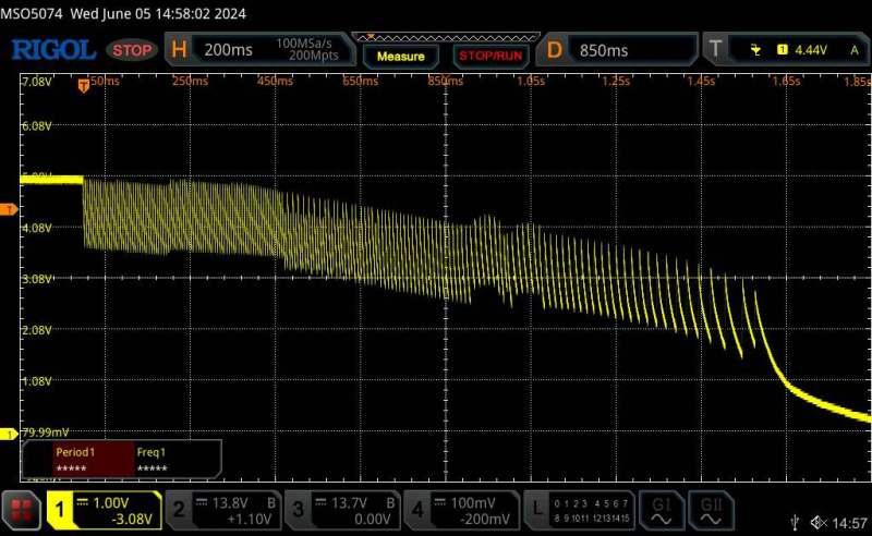 Edited 2024-06-05 16:50 by KeepIS It's all too hard. Mike. |
||||
| -dex- Regular Member Joined: 11/01/2024 Location: PolandPosts: 99 |
Thanks KeepIS for the photos of the waveforms. Maybe instead of looking for an idea to discharge the caps, it would be much easier to use a linear voltage regulator instead, as nickskethisniks suggested earlier |
||||
| nickskethisniks Guru Joined: 17/10/2017 Location: BelgiumPosts: 458 |
So, if I'm right the problem only occurs when bleeding of the capacitors, and is caused by the slow ramp down or up? Possible suggestion: For Auto start Instead of the Small toggle switch we could use a 3 position 3 pole Cam rotary switch. (or something simular) and also remove the diode coming from the bulk caps. This would allow to keep the controller board powered on or off without the influence of the precharge resistor or bleeding resistor.  Its possible if we want to keep it cheap we need a 4 position switch. And then it would look like this:  Yes, but I think my post was maybe irrelevant because of other usecase and because of wiseguy findings could also explain my problem, removing a dcdc lowered also the capacitance and in the system speeding up capacitor discharge curve. Edited 2024-06-05 18:58 by nickskethisniks Footnote added 2024-06-05 19:18 by nickskethisniks (were I thought it was a negative spike, wiseguy proved it was actually a slow ramp down/up on a certain "plateau") Switching out the switcher could or could not work, but might me worthwhile trying. |
||||
| wiseguy Guru Joined: 21/06/2018 Location: AustraliaPosts: 1156 |
I have been brewing quite a few ideas which include an active strong pull down on the resevoir caps once the inverter is switched off. That could extend to a strong pull down on the 12V rail when turned off or even just becoming active when the main capacitors start to droop say below 30V. I personally dont want to give a knee jerk response on how best/simplest to deal with this. Even a series pass FET between the 48V input of the card to the 12V regulator that only turns on with > 30V. I also thought about extra load on the 5V regulator it might work but wastes a bit of power, and its counterintuitive killing the input below say 30V seems like a sound approach. Still thinking of how to tackle it. I've now taken my tablet sorry for the earlier terse response  Edited 2024-06-05 18:58 by wiseguy If at first you dont succeed, I suggest you avoid sky diving.... Cheers Mike |
||||
| KeepIS Guru Joined: 13/10/2014 Location: AustraliaPosts: 1679 |
Hi Mike, I could tell you have been working hard, and burning those candles. IMHO this really is minor, it was just interesting as to why. dex I have considered the idea of a 5v linear regulator, it could solve the waveform, and we should try that as a fix for the LCD, or put a 5V LVDO regulator on the LCD board supply. I mentioned previously that I suspect the USB micro on the Nano PCB is the problem, not the Nano micro, I would like to find out for my own interest, if nothing else. As WG found, moving the rail at a very low voltage (around 1.8v) caused the TX led to flash, that could be the USB micro, the TX-RX LEDS are driven from the USB Micror, granted the Nano drives the signals to it, but I found no evidence of the Nano processor driving any other Pins. Does not mean much, but it is what I found. The USB controller also drives the Nano reset, if it's the USB, it would likely be resetting the Nano as well. The fly in the ointment is the Nano BOR, it's also around 1.8v, depends on who you believe, and that coincides with WG test at around 1.8v. what is the BOR on the USB micro - I know, who cares, likely just me! Repeated brownouts should not cause program corruption in a decent Micro controller, and it does not appear to worry the Controller Nano. The LCD Nano is getting it's program screwed by it's own bootloader and USB micro at reset, because of the 5v voltage variation. Why does the Controller Nano not have a problem? - I know, another, "who cares". In any case - remove the stupid bootloader code - remove that problem. But I would like to improve the 5v rail anyway - so I have a few simple things to try that require NO modifications to the Controller - A different regulator, if that is warranted is not a modification in my eyes, there are already 3 options for that part catered for. . Edited 2024-06-05 19:07 by KeepIS It's all too hard. Mike. |
||||
| KeepIS Guru Joined: 13/10/2014 Location: AustraliaPosts: 1679 |
A slow SPWM ramp down of AC output is not the cause. When you turn off the inverter the AC load is disconnected by Firmware. So you are waiting for the idling inverter to discharge them, I often put a 20 ohm resistor across them when testing, I still have to short the mongrels after waiting a few seconds, usually over 7v still there. Capacitor bank bleed down is only a problem when you get below 12V. This is where you might need to discharge quickly, but not really a problem until you get a slow discharge below 5 Volts, AND worse if there is noise on the rail, especially the waveform I showed. But the controller itself does not appear to care about that (IN MINE !!!) In my case <5V on the inverter DC input, is when you want to drop quickly to < 1v. This does not have to be complicated. Changing Auto start and wiring because an LCD has a dump all on it's own - caused by a dumb bootloader enter sequence on the LCD Board, These bootloaders should not be kicking in. . Edited 2024-06-05 19:43 by KeepIS It's all too hard. Mike. |
||||
| -dex- Regular Member Joined: 11/01/2024 Location: PolandPosts: 99 |
The LCD Nano is getting it's program screwed by it's own bootloader and USB micro at reset, because of the 5v voltage variation. Why does the Controller Nano not have a problem? - I know, another, "who cares". . I will repeat once again - amnesia also affected the nano controller. It was rarer than the lcd nano (maybe the length of the cable to the lcd). They never broke at once. I'm sorry, but I don't have it recorded. So who cares? At least one more user. I also don't consider this problem to be critical, especially since what I did works. However, it was very irritating when sometimes if I wanted to start the inverter I had to first upload code again  Regarding the TX and RX flashing caused by CH340. I think you said you have many versions of the nano, maybe you also have the original nano? The original uses a different chip as a USB controller - FT232R, perhaps it doesn't have bad behaviur such as Chinese IC. Edited 2024-06-05 19:48 by -dex- |
||||
| nickskethisniks Guru Joined: 17/10/2017 Location: BelgiumPosts: 458 |
Sorry, I meant the ramp up/down of the 5V rail. (And with "if I'm right" I meant "If I'm understanding it correctly", some things get lost in translation if writing to fast, I'm trying to avoid translation tools...  ) ) |
||||
| KeepIS Guru Joined: 13/10/2014 Location: AustraliaPosts: 1679 |
Yes difficult on the forum to convey meanings sometimes, also one of my problems even without translation  Thanks Dex, that really helps as it removes that one question I had. So the old screwed bootloader erasing the program jump entry point, or erasing program memory. As I said the other day, I also don't use the bootloader in either Nano now, just wasted space. I'm using the same Nano boards as shown in your video, most of the time, but I have another that lives in the Inverter and that is the same board but has the better USB chip set. The LCD is a more expensive clone, it had a faulty pin, pin was not needed for the LCD, so it ended up there. Likely why that Nano has never failed. So now I only have to make the decaying 5v look pretty, I'm not worried either way at this point as it has not skipped a beat. Not using the bootloader ensures that stupidly cannot happen. Thanks for putting me right on that - lost in translation  . Edited 2024-06-05 21:22 by KeepIS It's all too hard. Mike. |
||||
| wiseguy Guru Joined: 21/06/2018 Location: AustraliaPosts: 1156 |
I may have a solution so I'll throw it out to the forum for comment. I want to start by saying how much this sucks that the boards are in production and we now find out about this glitch at the 11th hour. I expect the boards will be despatched (back to me from JL) late tomorrow. So to the problem, everything is fine at 16V or more, below 12 and closer to 6 we have issues. Whilst considering creating hex code to upload to the Nano as the fix I am still nervous about what I have seen and the possibility that there might still be random things to go wrong. Maybe the final solution will be code and hardware mod ? With all this in mind what if we could turn on the power from the 24/36/48 whatever, when the input voltage is above 16V. with this in mind my simplest solution I can think of is in the attached picture. Please note the bread-boarding area right adjacent to the 48V and regulator was a last minute addition - just in case. I would also probably cut the track such that the 220u is on the source of the FET to ensure the regulator switches off as fast as possible. 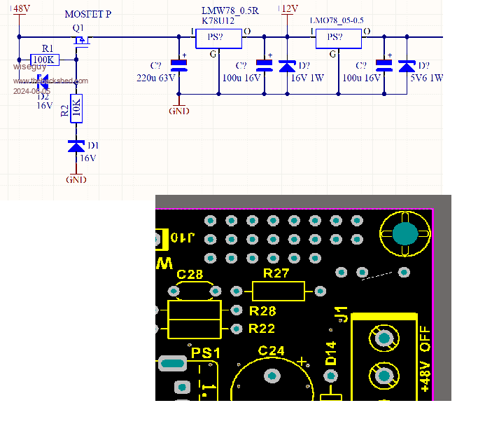 So above 16V - probably closer to 19V the P channel FET will turn on and supply the battery input to the 12 & then 5V regulators. The second zener protects the gate voltage from being exceeded. Below 16V input the FET is hard off. If there is consensus I probably have enough Pchannel TO220 FETs to supply for each Inverter main board/controller ordered and certainly enough Zeners to throw in too and they can all be shipped out at once ? I will of course create a few pictures of how to add the Mod and parts to make it work. Edited 2024-06-05 22:04 by wiseguy If at first you dont succeed, I suggest you avoid sky diving.... Cheers Mike |
||||
| -dex- Regular Member Joined: 11/01/2024 Location: PolandPosts: 99 |
If I could suggest anything, to be sure to get rid of the pulsing, I would do it on the 5V line. For example, SCR (with resistor in series) on the 5V line to ground and its gate controlled by uC - maybe pin A7 could be used for this? In the turning off phase, Nano monitors the dc voltage and when it sees that it drops below 20V (or any voltage you programm), it activates the scr gate and discharge everything what is on way. Or just simply use 7805 in place of PS2. nanos in mppt brain boards are done this way at my config (dc-dc converter -> 7805). No problems with flickering and amnesia, but litle more heat. |
||||
| KeepIS Guru Joined: 13/10/2014 Location: AustraliaPosts: 1679 |
For a long time, I have coded the Nano to consider the Power OFF state as: Low battery cutoff voltage / 2. With a minimum of 18v whichever is higher. At that point, the Code does nothing. I have thoroughly investigated the Pin status of the Nano under this very low noise voltage. The pins are not glitching, even when I forced all lEDs to flash < 4v, and even if they did, it can do nothing to the inverter at these low voltages. A main inverter DC voltage of 5 volts or less can do nothing to the physical Inverter. This leaves only the worry that the Nano code might get corrupted because of noise on the 5V rail at cutoff, and effect startup. I doubt it, but that is only an opinion, so it means nothing. If the code was corrupted, I seriously doubt the Nano could even start the inverter, again an opinion. I have a day away, so I can't do a simple test I was planning until this evening. I am 100% confident that my inverter, without a booloader in the Nano, will not fail because of the 5v rail noise as the regulators cuts off. I'm not suggesting that we don't at least have look at it and clean it up a little. I admit that the stability of the this Nano microprocessor in the field is an unknown for me. So I'm trying to tread very carefully here - these are just my thoughts, but they are based on many years of older industrial micro controller programming - including writing bootloaders that don't do what this stupid bootloader is doing  . Edited 2024-06-06 08:49 by KeepIS It's all too hard. Mike. |
||||
| -dex- Regular Member Joined: 11/01/2024 Location: PolandPosts: 99 |
Finally, I managed to connect the target battery set: 16x 280Ah lifepo4. This time there was no fire  I will soon send some photos of how it was done So far, I have tested everything on small loads, now I can go further. Oops.. no I can't. It turns out that there is a problem with voltage collapse under load. It appears that the relationship load/voltage drop is linear. Below is what I managed to catch on the meter in the application. When the voltage drops this low, the inverter turns off. Voltage regulation with a potentiometer on the controller board works properly, currently I have it set to 230V. No load/tiny load sits on ~ 230V. Small load small drop, large load large drop. Currently the KeepIS code is loaded, but I also saw this problem with the Poida code earlier, it's probably not a problem with the code, but with my configuration. I also know that in the case of KeepIS build the AC voltage is very stable. There is a problem with my build, but I have no idea what is causing it. Do you have any suggestions? One final note: measurements taken when all MPPT were off. 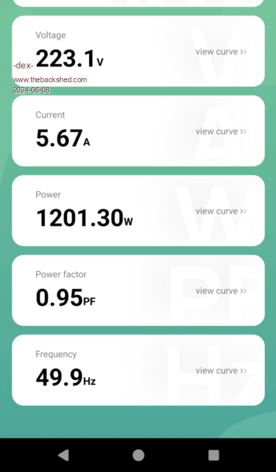 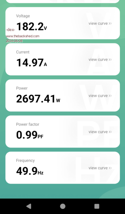 Edited 2024-06-08 19:56 by -dex- |
||||
| wiseguy Guru Joined: 21/06/2018 Location: AustraliaPosts: 1156 |
I am sorry Dex you are in KeepIS's hands here I have no idea what the code is up to. The only query I have is did you ground the Nano pin A7? In the Poida code we had a similar issue but a dummy read of A7 between the Amps reading and the VFB feedback reading solved it. The fact that KeepIS has an inverter that is very stable indicates that there must be a difference between his PCB and yours. One way to prove the point easily is to disconnect the current sense transformer and then load it up to 15A again and check the AC voltage - I suspect it will be fine. Don't leave the current sense unplugged like that but lets know the results of that test. Edited 2024-06-08 20:17 by wiseguy If at first you dont succeed, I suggest you avoid sky diving.... Cheers Mike |
||||
| KeepIS Guru Joined: 13/10/2014 Location: AustraliaPosts: 1679 |
You have a problem with voltage loss somewhere in the inverter or toroid, choke or filter wiring loss.. 1: measure the voltage across the DC input terminals on the Inverter Power board. The voltage under that size load should hardly drop, mine would see a voltage drop in the 100mv or less range. 2: Voltage loss across the chokes or toriod problem, but what we need to know first is the % of PWM in both cases, it should only change a few %. That would mean either DC voltage is falling to the inverter or a toroid / choke problem, both could cause the inverter PWM to hit the max 99%. I assume the info above is from a dedicated AC monitor. Even the $36.00 ones I use are surprisingly accurate. The only other thing is something not right in the feedback circuit or the Toriod winding ratio is having trouble with some voltage drop and cant maintain regulation, again 99% PWM This is just off the top of my head - and I'm tired, so I may be off base on a couple. But at least nothing is going bang - always a good thing  . It's all too hard. Mike. |
||||