
|

|
Forum Index : Electronics : I'm ordering mppt and inverter PCBs - who wants what?
| Author | Message | ||||
| Cobbler Newbie Joined: 25/01/2023 Location: AustraliaPosts: 14 |
Thanks Poida, that makes is a lot simpler and quicker to start testing. Based on the code, I am assuming the pot wiper is connected to A0 and the pot ends between +5V and Gnd, right? Cheers Michael |
||||
| poida Guru Joined: 02/02/2017 Location: AustraliaPosts: 1418 |
yes. all analog inputs go from 0 to 5V wronger than a phone book full of wrong phone numbers |
||||
| Murphy's friend Guru Joined: 04/10/2019 Location: AustraliaPosts: 648 |
Goodness, you have dredged a long way back for that  There were quite a few different saturation testers discussed on this forum over time. I like warpspeed's design because: It does not require programming anything (I'm no good at that) It continually bounces current back and forth through the coil automatically. No need to fiddle with switches or connections, just watch the scope trace as the input voltage is slowly wound up. With the Aerosharp C core choke the saturation knee is quite sharp, not so with the toroidal powdered iron choke I tested recently. But its not possible to have a removable test coil for that type core. But, it requires a hall sensor that senses DC. And it requires a test coil with many turns of smaller diameter wire than the planned choke coil. Such a test coil would saturate at a relatively low current, one can then interpolate by the turns ratio when the planned choke coil would saturate without having to rely on a power source capable of many hundreds of Amps. I use a power supply capable of 20V & 6A flat out. |
||||
| Cobbler Newbie Joined: 25/01/2023 Location: AustraliaPosts: 14 |
When I started searching the forum for inductor saturation testers I remembered warpspeed's hand sketched idea from a few years ago because I really liked the current recycling feature so I was happy to find a full circuit design based on that. My understanding is that a suitably rated (or shunt assisted) LEM current sensor should be compatible with that circuit and allow testing the fully wound choke at full current but I am only guessing at the moment. Please correct me if I am wrong. While I would really like to fully build one of these saturation testers, I will try Poida's suggestion using the simple nano based tester and see how I go with that. Fortunately, I have a pretty capable power supply that can handle up to 14A at 50V and all I need is a few large caps, a LEM and a HY4008 to get started. Cheers Michael |
||||
| mab1 Senior Member Joined: 10/02/2015 Location: United KingdomPosts: 209 |
In case anyone else was looking for Poida's serial LCD conversion using a nano - here's the link:- https://www.thebackshed.com/forum/ViewTopic.php?TID=13650&PID=194228#194228#194228 rather handy as i have a few old LCDs to reuse; two 20x4 and two 40x2 which you don't see too often. |
||||
| poida Guru Joined: 02/02/2017 Location: AustraliaPosts: 1418 |
Any FET will do, choose low voltage, for lowest Rds(on) There must be something lying around. A lot of FETs will nearly fully conduct from the 5V driven by the nano. Maybe you have a dead UPS. Inside will be some 50V FETs with a good low ON resistance. And you can do it without a current sensor too. I got very useful results, that let me finalise the inverter choke I used for the house inverter by using a single strand of about 1mm copper wire as a current sense. It was about 30mm long. You first determine the resistance (put 10 Amps through it and see the voltage) and then use 1x gain on the probe, turn up the vertical gain on the DSO and it works. Put the wire on the ground connected lead that goes to the inductor. All probe connections must use the same ground point 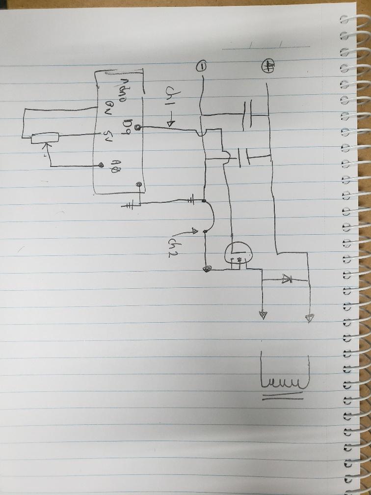 Edited 2023-04-06 08:32 by poida wronger than a phone book full of wrong phone numbers |
||||
| Cobbler Newbie Joined: 25/01/2023 Location: AustraliaPosts: 14 |
I have a few IRFB3006 which will hopefully work well enough driven by the nano. Thank you for the sketch and wire shunt suggestion. I will start experimenting as soon as I get a chance. Cheers Michael |
||||
| poida Guru Joined: 02/02/2017 Location: AustraliaPosts: 1418 |
Cobbler: I did a bit more playing with the choke tester. I added a TLP250 opto isolated gate drive to the hack and it now drives the Gate to 12V, very fully making it switch ON with the lowest resistance. I found I could not get much more than maybe 90 Amps into a choke. After this, it goes to 475 Amps... So the 5V or more likely the 4.7 or whatever out of the Nano/Uno was not enough for more in depth explorations of choke saturation. 475 Amps, 12V implies a total resistance of 25 mOhm which includes the 6 mOhm from the FET I use. Everyone: here is the "serial LCD" I refer to https://www.thebackshed.com/forum/ViewTopic.php?TID=13650&P=9#194228 Easy to build and so useful for my experiments and builds. wronger than a phone book full of wrong phone numbers |
||||
Bryan1 Guru Joined: 22/02/2006 Location: AustraliaPosts: 1344 |
Mike came for a drive up this morning to get that tape and connectors and kindly brought up an aerosharp for me to play with   We talked about that 6.5X4mm(not 5 Mike) is 26 mm squared so it should be good for my first inverter. Now this wire came out of that E-core and in order to use it I had to anneal the wire first using my 2 ring crab burner and using a HP reg to get the right flame and left it heating for about 2 hours turning the core so all sides had a chance to get that red colour which what we want.  We did work out for that 15 turns we talked about for 24 volts I'll need over 5 metres to get the turns. I found atleast 5 metres of heatshrink to insulate the copper wire so the primary will be a few colours  Now as I have a heap of fets I reckon it reckon I'll be doing everything I can not to join that blown fets club  I do have this board 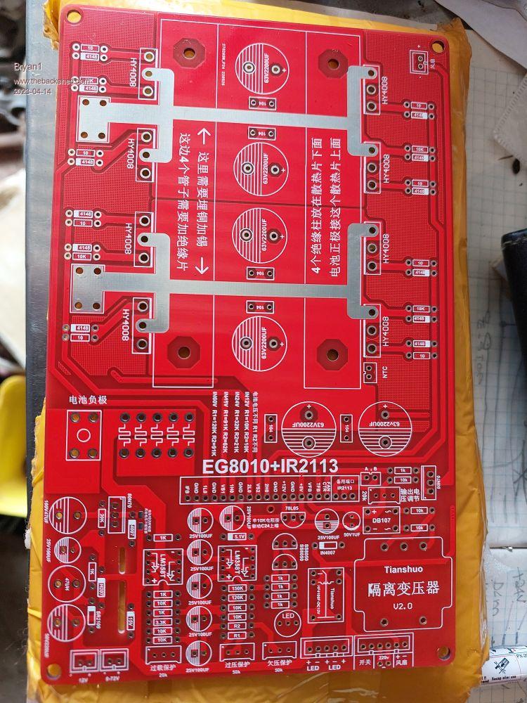 I do think I have seen this type of board used before and the best part I reckon I have all the components here to make it and any help will be nice as no info came with this board. Cheers Bryan Cheers Bryan Edited 2023-04-14 16:13 by Bryan1 |
||||
| pd-- Senior Member Joined: 11/12/2020 Location: AustraliaPosts: 122 |
Sum of the Arduino Nano clones are just rubbish I just loaded up a nano clone with the MPPT code and plugged it into the brain board and was greeted with a LCD of random characters & symbols . So i loaded up a simple little " hello world " program using the standard serial libraries and still junk. So after lots of fluffing around the cro came out and the serial timing was up the sh**t it was around that time that i realized the CPU had no markings and the 16mhz xtal was missing from the nano. it turns out the chip was running at 5.3 MHZ so if i set the baud rate to 28800 i get a serial port that runs at 9600 i haven't bothered seeing what else is wrong with it. so if all else fails throw away the nano and get another one |
||||
| poida Guru Joined: 02/02/2017 Location: AustraliaPosts: 1418 |
pd-- first I've heard of this. Thanks for the heads up wronger than a phone book full of wrong phone numbers |
||||
| poida Guru Joined: 02/02/2017 Location: AustraliaPosts: 1418 |
Bryan1: here is a schematic of something close to what you have. It will help you understand the various functions (low voltage shut down, over DC voltage shutdown, the two current limits etc) 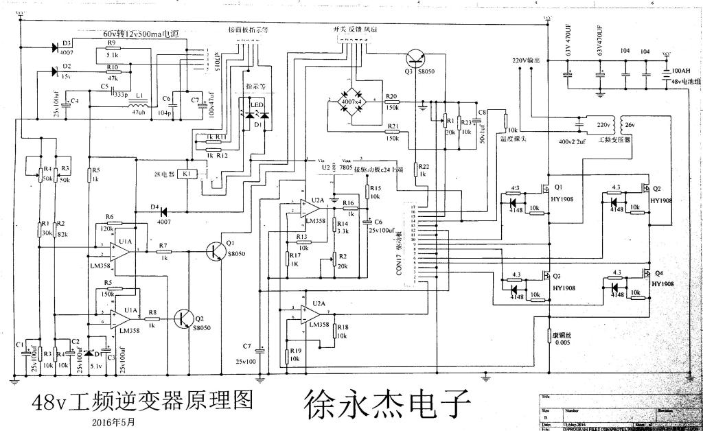 That board you have uses the EG002 module to provide FET Gate drive and so it is prone to out of spec. voltages appearing on the IR2110 outputs. This can cause blowups. You could build a minimal version of this, without all the above functions. That is what I would do. Just put the AC voltage feedback stuff in, a 5V supply, a 12V supply. Put a socket where the EG002 module goes too. Disable the over current stuff on the EG002. This will be educational and be fine for low power tests. 5V supply to the EG002 will start the inverter. No 5V will stop it. If you want to do high power, I would want some TVS Diodes on the 4 Gate drive outputs, located close to the EG002 and mounted such that they prevent negative voltages reaching the EG002 outputs (1LO, 2LO, 1HO, 2HO) The high outputs 1HO and 2HO are NOT referenced to DC ground. They are referenced to respectively VS1 and VS2. wronger than a phone book full of wrong phone numbers |
||||
| Cobbler Newbie Joined: 25/01/2023 Location: AustraliaPosts: 14 |
Thank you for taking the time to upgrade and test the circuit with an optocoupler and letting me know ahead of my tests. Looking at the MOSFET charts I can see most of them need at least 8V GS to start conducting close to their rated Drain current. I should have a couple of spare TLP250 already but I need to order 4 additional Sendust ring cores and 4x E70 Ferrite cores before I can start testing. I have decided to order 2 of the distributed gap type B66371Q0400K187 with 0.77mm G2 and 0.4mm G3 air gaps and 2 non gapped B66371G0000X187 cores to avoid having to grind a gap myself. This combo provides the smallest commercially available gap and I hope it will be suitable for the choke. I have ordered a few TIP41/TIP42 Totem pole transistors for the Inverter project but in the final build I would have liked to use the better spec. 2SA2040/2SC5707(2SC5980) complementary bipolar pair used by wiseguy. Unfortunately, 2SA2040 is now showing as obsolete/ 0 stock with all major distributors (except Rochester Electronics) and 2SC5707(2SC5980) are only available in the TL-E surface mount package (except from a couple of non authorised distributors (https://www.digipart.com/part/2SC5980-E) so I have spent a bit of time looking for alternatives (see list below). I know wiseguy's design uses isolated supplies with the 2SA2040/2SC5707 transistors which have a VCE of only 50V while the TIP41C/TIP42C have a VCE of 100V so I would like some help understanding the 100V rating specified for these parts. I realise VS1 and VS2 alternately swing between VBAT and GND and the high side Totem poles only see a maximum of 18V DC between Collector of TIP41 and Collector of TIP42 as they are floating above VS1/VS2 and are referenced to these lines (instead of GND) so I would expect even transistors with a VCE of 50V should be suitable. Am I missing something here? In any case, here are the alternative parts I have found for the Totem pole pair. Any comments on their suitability would be welcome, thanks. The following parts have an fT of 330MHz and very fast rise and fall times: onsemi 2SC6144SG NPN Transistor, 10A (cont)/ 13A (pulse), 50V, Low VCE(sat) NPN TO-220F-3FS https://au.rs-online.com/web/p/bipolar-transistors/1844163 https://docs.rs-online.com/5734/0900766b81709b4d.pdf onsemi 2SA2222SG PNP Transistor, 10A (cont)/ 13A (pulse), 50V, Low VCE(sat) NPN TO-220F-3FS https://au.rs-online.com/web/p/bipolar-transistors/1844158 https://docs.rs-online.com/c554/0900766b81709b4c.pdf The following parts have an fT of 60MHz (NPN) and 40MHz (PNP) whereas the TIP41/TIP42 fT is only 3MHz but if I am reading the chart correctly, the rise and fall times appear to be only slightly faster at 5A IC. https://docs.rs-online.com/e9d0/0900766b8160e104.pdf onsemi D44H8G NPN Transistor, 10A (c)/ 20A (p), 60V, 3-Pin TO-220AB https://au.rs-online.com/web/p/bipolar-transistors/5450163 onsemi D45H8G PNP Transistor, 10A (c)/ 20A (p), 60V, 3-Pin TO-220AB https://au.rs-online.com/web/p/bipolar-transistors/5450185 onsemi D44H11G NPN Transistor, 10A (c)/ 20A (p), 80V, 3-Pin TO-220AB https://au.rs-online.com/web/p/bipolar-transistors/6255076 onsemi D45H11G PNP Transistor, 10A (c)/ 20A (p), 80V, 3-Pin TO-220AB https://au.rs-online.com/web/p/bipolar-transistors/5450179 The semiconductor shortages (and prices) seem to be getting worse day by day with some components showing lead-times into next year so I better get cracking with my projects before it becomes impossible to source the parts. Edited 2023-04-18 05:17 by Cobbler Cheers Michael |
||||
| wiseguy Guru Joined: 21/06/2018 Location: AustraliaPosts: 1156 |
Recently I went through the same process to find suitable transistors/alternatives. I found these at LCSC and bought 40 of each as I saw the end looming. Their transistors to date such as HY4008 and HY5608 are always genuine and meet spec. The two I bought are below but I just checked and there is nil stock left now. NPN Manufacturer, UTC(Unisonic Tech), Mfr. Part # 2SD1804L-T-TM3-T, LCSC Part # C85223 PNP Manufacturer, onsemi, Mfr. Part # 2SA2040-E, LCSC Part # C165093 With regard to your question about the hundred volt rating, it means that between collector and emitter they will not break down at 100V (also check that max vcb is not exceeded) providing the current max is not exceeded or the internal temperature rise due to dissipation from a linear function is not exceeded and they will survive indefinitely. This rating is from design and the transistors will function just fine at lower VCE voltages. If I had to choose between two transistors with essentially the same specs but one had a 100V max rating and the other had a 50V max rating and they were for driving gates at 12-15V I would choose the 100V version. Why? Because having that transistor in my parts bin means if I ever have an 80V application I can use them - nothing to do with the required 12-15V application. In the application with a 12V-15V supply for driving gates on and off it is not really a very demanding task and any transistor with a max collector voltage of 20V or more could be used. If you ever look at Zetex transistors for demanding gate drives they have a range of high current devices at quite low voltage specs such as 20/25/30/40V etc. I cant really comment further on the other devices you suggested as I have time constraints at the moment. Get cracking and buy what you need now - I believe it will still get worse before it gets better. If at first you dont succeed, I suggest you avoid sky diving.... Cheers Mike |
||||
| poida Guru Joined: 02/02/2017 Location: AustraliaPosts: 1418 |
Even the TIP41/42 combo will work fine. The primary reason I like the totem pole drive, located close to the FETs is the isolation it provides from the large voltage swings coming out of the Gates (due to dV/dt or dI/dt) that can not pass back to the gate drive IC output pins. This makes the power board and inverter controller board much more robust and able to take unreasonably high peak loads without failure. The speed of Gate drive is not so much a problem, more something to optimise if one has the time or interest. This can reduce some power losses. I am sure your build will be quite efficient and have low switching losses no matter which transistors you choose. wronger than a phone book full of wrong phone numbers |
||||
| wiseguy Guru Joined: 21/06/2018 Location: AustraliaPosts: 1156 |
Agreed almost any half reasonable buffer is better than no buffer I prefer to think of the buffer as a low impedance device rather than an isolator. The gate of the mosfet is influenced by dVdT events on the Drain. If there were no means of controlling (limiting) the gate voltage the FET can be permanently damaged. A low impedance buffer stage with minimal inductance/resistance helps to achieve this. This is why longer cables connecting drive signals to the FETs are a bad plan due to increase R and L. The buffer stage is typically a very low impedance that either drives and holds the Gate at +12 or at 0V. If the impedance between the buffer and the gate is too high then dVdT effect on the gate may inadvertently allow the FET to turn on. This may or may not be catastrophic depending on whether it causes a shoot through event. The Gate is easily damaged by exceeding the max limits which are typically +/- 25 or 30V but can be as low as +/-5V. A 15/18V Transorb directly across the FETs gate and source connections should prevent the FET from excess V gate damage. The Buffer stage should also be in close proximity to the FETs Gate and source so it too can clamp the gate at either 12V/0V. The Buffer stage provides some(more) protection to upstream parts which are more easily damaged when output FETs combust. A diode can be placed across the gate resistance (anode to gate) to lower the gate impedance when the buffer is at 0V When output FETs combust, the 48V on their Drain can feed 48V out the Gate back to the buffers driver ICs etc. The Transorb across the FETs gate and source will not protect the FET from excessive Drain over current or over voltage abuse. I did not like my previous attemt to describe this concisely after I re read it. Also agreed. But if for instance the buffers were on the driver board and longish connecting cables then the increased gate impedance of the cable is not be enough to guarantee good protection to the gate, even if the damage will still be minimised to the up stream bits. Edited 2023-04-19 20:28 by wiseguy If at first you dont succeed, I suggest you avoid sky diving.... Cheers Mike |
||||
| flyingfishfinger Senior Member Joined: 12/09/2020 Location: United StatesPosts: 110 |
Will add to this. My Nano clones don't have the full advertised flash space I ran out in the low 90% trying to flash the MPPT code. I got around the issue by truncating all the menu wordings to the minimal recongnizable abbreviations and saved ~5% space, then it fit. On a fun note, using software I2C somehow saves another couple percent over hardware I2c (weird!) R |
||||
| Ziki_the Newbie Joined: 13/04/2023 Location: YugoslaviaPosts: 39 |
Hello everyone  i'm fresh on forum. i'm fresh on forum.Is it possible to order boards for Mppt? If so, what is the procedure? Shipping would go to Serbia... Thanks Pozdrav iz Srbije |
||||
Madness Guru Joined: 08/10/2011 Location: AustraliaPosts: 2498 |
Some of you may find this useful, it works with the Nanoverter serial display. Poida might confirm if it is compatible with the Picoverter. It is much simpler to put together than just using wires and hot snot. It includes brightness and contrast adjustments and looks more pro too I think. Madness Nanoverter LCD piggyback.zip 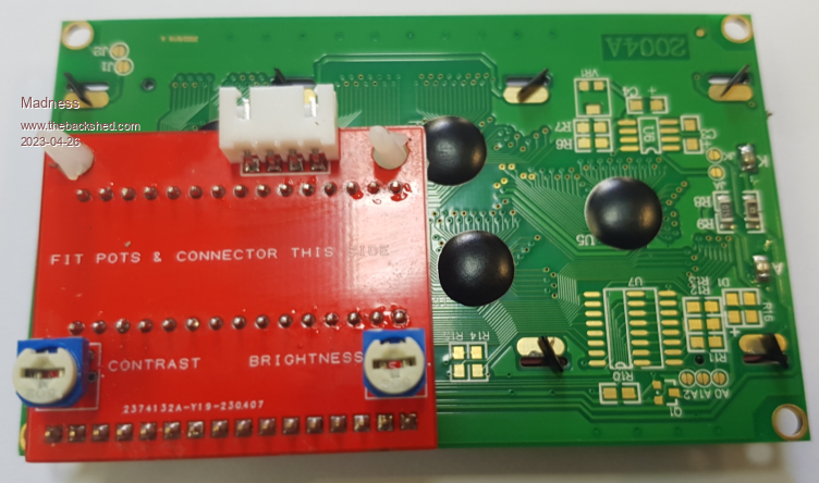 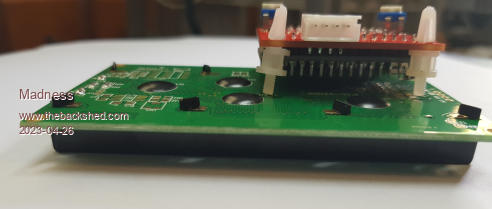 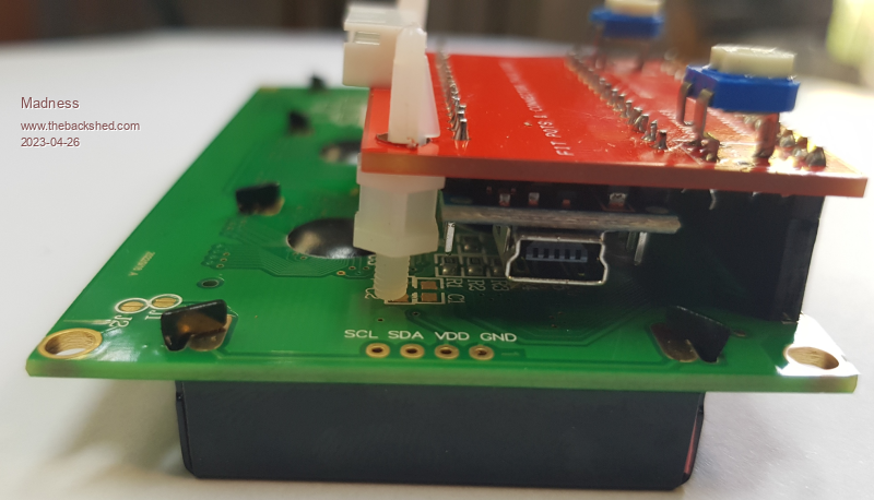 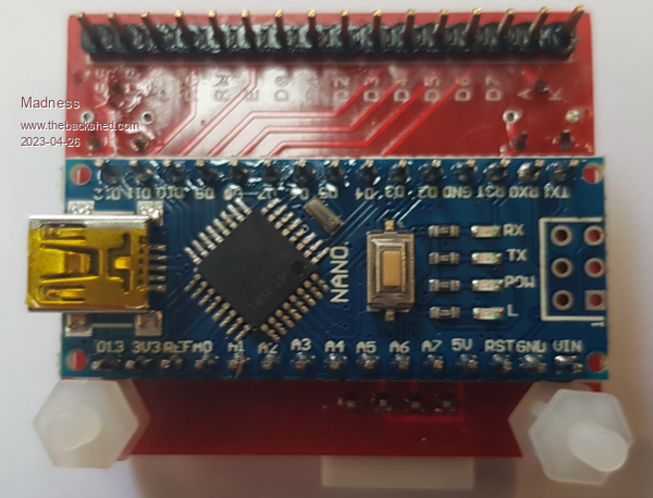 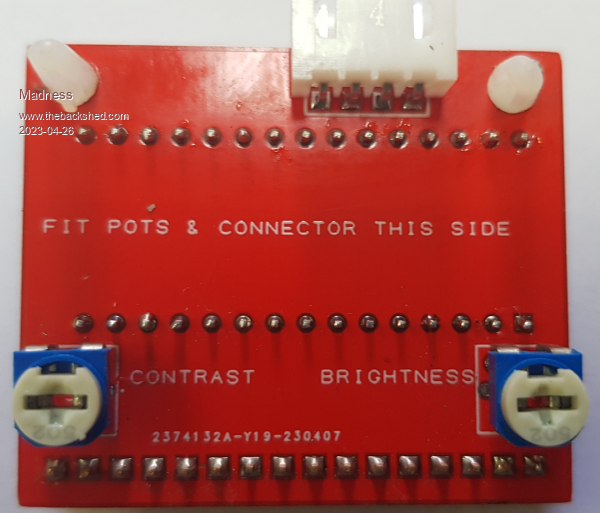 There are only 10 types of people in the world: those who understand binary, and those who don't. |
||||
| poida Guru Joined: 02/02/2017 Location: AustraliaPosts: 1418 |
Sorry to say I have sold all mppt boards. I have sent boards to UK, Italy, Belgium, France so Serbia might be no problem. Typical cost was $35 AUD for postage. I don't want to order 5 more boards just for you since the cost of freight per board can be rather high. It's far better to order 20 boards. wronger than a phone book full of wrong phone numbers |
||||