
|

|
Forum Index : Electronics : Turning a Toyota Prius into a "portable" generator
| Author | Message | ||||
| nickskethisniks Guru Joined: 17/10/2017 Location: BelgiumPosts: 458 |
I'm following this project with great interest! I'm not an expert in pcb designs like others. So I don't know if I'm the right person to give some critic. But we are all here to learn some things. I like the "looks" of your pcb design, but there are some design flaws. I didn't see the bottom view, so I don't have the whole picture. Maybe you can post the whole design? My opinion, your gate driver's look close to your igbt's but they aren't, they are cm's away because there are heatsinks between, you could better place them on the other side of your igbt's, on the outside of your board closer to your igbt's. That way your current carrying track could be shorter. Probably there is also a current carrying track on the pcb bottom close and parallel to your gate tracks,you want to avoid that as well, it will act as an antenna. If you can't avoid that you need to cross your current carrying track under 90 degree angle to pick up as little noise as you can. In all cases you must try to keep gatedrive as far away as you can from the current carrying tracks. Your capacitors are far far away from your igbt's, they are in the inside and the power tracks are following the outside of your board. That way everything sensitive is "trapped" between noisy conductors. It will also have great inductance and this will cause fast voltage spikes. You can buffer-cancel it out a bit with low ESL/ESR caps verry close to your igbt's. I think you can get away with this at lower voltages, but the higher the voltage, the faster the transitions (dU/Dt)will be. And the higher the spikes on your DC bus, or more precisely between collector-emittor. Slowing down the gatedrive could help with reducing this. I would also twist your wires coming from your brainbord to the power pcb. Or use ribbon cable, it's probably the least important bit. But those wires can pickup some noise as well and this will go to the brain board. Don't let the wires go over your powerboard, let them also leave the pcb under 90 degrees, this should reduce the amount of noise it will pick up. I don't know if this design is the cause of your problems, I would certainly invest in an oscilloscope at this stage. Sorry if I'm to hard on you, I just want to help and think with you. I would certainly add those low ESL/ESR caps to start with, place them verry close to your igbt's , 1 each push pull stage. Edited 2021-01-15 08:02 by nickskethisniks |
||||
| Haxby Guru Joined: 07/07/2008 Location: AustraliaPosts: 423 |
Yes an oscilloscope purchase is now inevitable. My photos may look misleading There is less than a fat thumb distance between gate and gate drive resistor R6. All gate drive layouts are a cut and paste of this one. Can't get much tighter, but the leads to each opto driver IC are currently about 6 to 12 inches and not twisted, so I can fix that up easily. Though they are low impedance and floating since they only activate the opto led, so I don't think they are the problem. 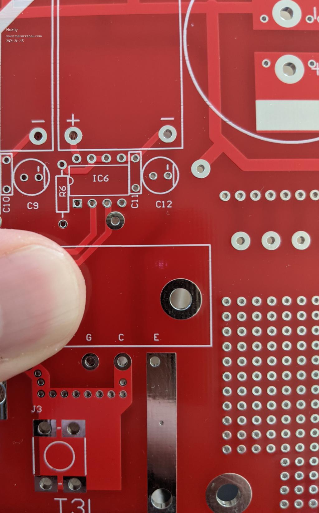 The distance between caps and the IGBTs is of concern. When I was designing the board, I designed for the largest inverter to be closest to the capacitors, as that's where most of the current will be circulating. Each power track also has a copper bar soldered to it. For now I'm convinced I'm experiencing voltage overshoot. The oscilloscope should prove that. So I'll concentrate on lowering on/off time, increasing bypass capacitance and maybe adding a low value snubber capacitor between C and E of every IGBT. Any recommendations for an oscilloscope? |
||||
| Warpspeed Guru Joined: 09/08/2007 Location: AustraliaPosts: 4406 |
This is how I built mine three years ago. I have given this a great deal of thought since, and still cannot think of any ways to improve on the basic layout or concept. Good quality low esr electrolytics mounted on heavy busbars, with the shortest possible physical distance to the IGBT half bridge power blocks. The gate drivers are on the opposite side to the collector outputs which drive the two largest transformers. Its very simple "nuts and bolts" construction, and easy to make, and changing an IGBT only takes a few minutes without requiring a soldering iron or 230v power ! 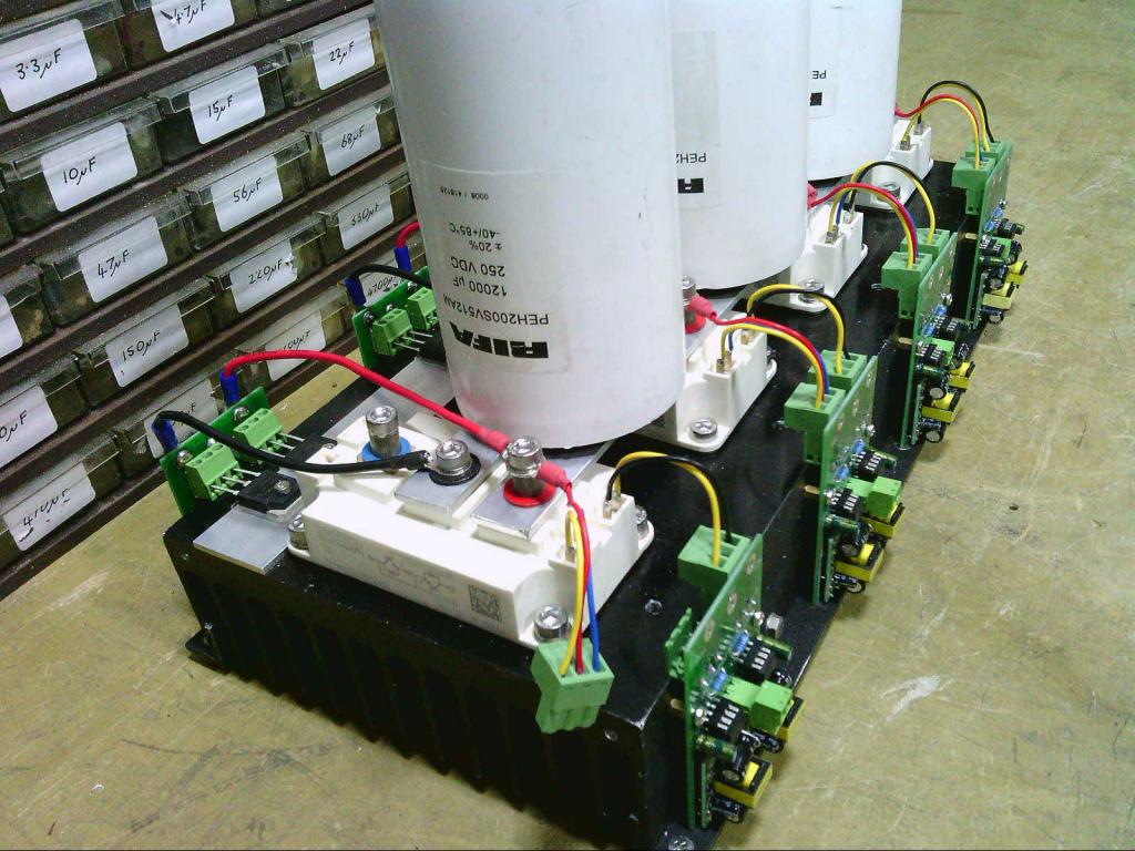 The two smaller inverters are on the other side of the heatsink. 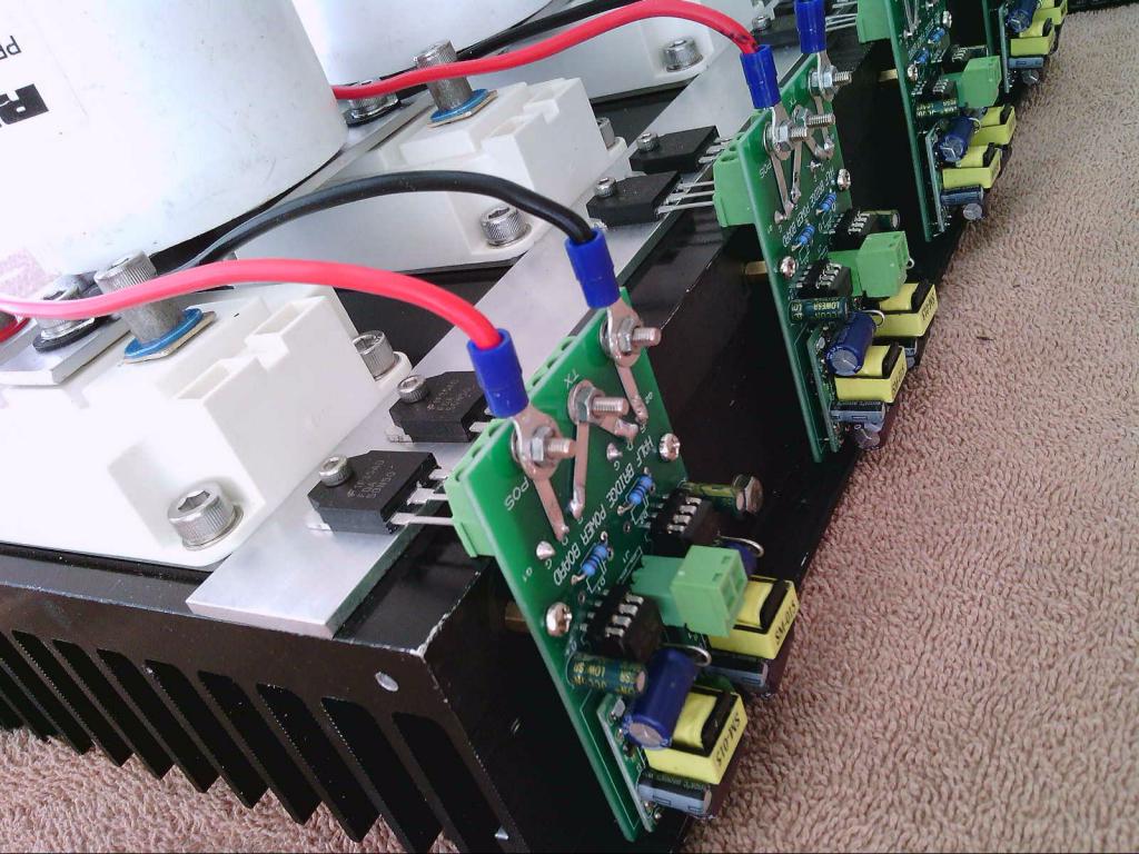 The twisted pair connections back to to the control board plug into the green connectors, and can be made as long as required without any possibility noise pickup problems. Cheers, Tony. |
||||
| Haxby Guru Joined: 07/07/2008 Location: AustraliaPosts: 423 |
I meant to say INCREASING on/off time! |
||||
| Warpspeed Guru Joined: 09/08/2007 Location: AustraliaPosts: 4406 |
You beat me to the draw. That looks fine. Just as important as the distance to the electrolytics will be the type of electrolytic. Low esr type are going to be far more effective. Cheers, Tony. |
||||
| Haxby Guru Joined: 07/07/2008 Location: AustraliaPosts: 423 |
I'm using 9x560uF 450v Epcos brand caps salvaged from my ever-growing collection of aerosharp inverters. I can't find an exact datasheet match for the part number, but all indications are that they are suitable for switch mode power supplies, so should be low esr. Part number is B43252-S5567-M1 The oscilloscope should tell all. |
||||
| Warpspeed Guru Joined: 09/08/2007 Location: AustraliaPosts: 4406 |
I found the data sheet, but for some reason cannot link to it directly. Go to Element14 search their capacitor section for EPCOS 560uF 450v. Anyhow, it is definitely a low ESR type, and an excellent choice. Cheers, Tony. |
||||
| poida Guru Joined: 02/02/2017 Location: AustraliaPosts: 1418 |
I made a simple tool to visualise the waveforms of the warpverter. You need to download the programming thing called "processing" It is basically a java programming environment but easy to use. download, install and run, then load this trinary_vis.pde.zip and run it. it shows a perfect sinewave in Black, then the result of a 4 inverter warpverter, in Green, then the outputs of the 4 inverters in Brown, Purple, Yellow and Blue. The idea is these last 4 are added together to make the Green curve. You can drag the black rectangle up and down (with the mouse) to change the size of the sinewave, showing how the 4 inverter's outputs change at different times in the sinewave. It looks like this: 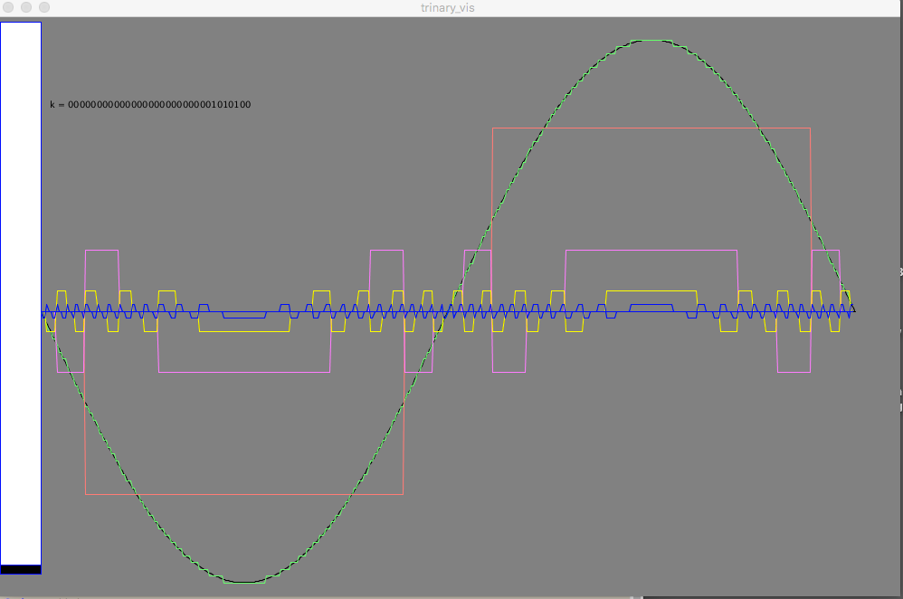 wronger than a phone book full of wrong phone numbers |
||||
| Warpspeed Guru Joined: 09/08/2007 Location: AustraliaPosts: 4406 |
That is just amazing Peter. It may be a simple tool to you, but its way beyond anything I could ever do. It took me literally years to work all this out and solve all the problems using basically just hardware. But it has all finally worked out much better than I ever dared to hope. It has no commercial value because the high cost and physical size of the transformers makes it uncompetitive. But for home brew, especially at very high power levels, it has rather a lot going for it. Edited 2021-01-15 16:36 by Warpspeed Cheers, Tony. |
||||
| poida Guru Joined: 02/02/2017 Location: AustraliaPosts: 1418 |
Warp, I just want to help us get our heads around the concept. Once you get the proportional voltage contribution idea, it just works. I tend to agree that this is the way for +6kW or so systems. wronger than a phone book full of wrong phone numbers |
||||
| Haxby Guru Joined: 07/07/2008 Location: AustraliaPosts: 423 |
Poida, did I read somewhere that you helped write some of the blue pill code that allows warpverter synchronisation? What would I have to do to synchronise 3x stm32's into a 3 phase warpverter setup? |
||||
| poida Guru Joined: 02/02/2017 Location: AustraliaPosts: 1418 |
yes, I wrote a demo code for a nano that could synchronise. I think if you want a 3 ph warpverter I will write something that will drive the 3 warpverters in 120 degree phase offsets and not need sync. I do not think phase lock will work well for this. My first thoughts are that it will be very possible when using the Mega (this uC has enough timers for 3 phase) I am holidaying at the moment and can not hack up something to prove a concept. 50 Hz, 3 phase, 4 toroids per phase would be the requirement? This means 24 bits output. wronger than a phone book full of wrong phone numbers |
||||
| Warpspeed Guru Joined: 09/08/2007 Location: AustraliaPosts: 4406 |
Yes basically three identical systems locked at 120 degrees. Andrew and I have discussed this. The hardware way would be to have three identical boards with three identical lookup tables driven by three counters. AC first positive zero crossing corresponds to the counters overflowing through 0000, so its just a case of providing a very narrow reset pulse to each of the counters phased 120 degrees. So basically three warpverter boards synchronised from an external 120 degree phased reset pulse generator. Pretty clunky but very easy to do. Its really hard phase forcing through counter reset, not a slowly correcting phase locked loop as such. The three systems could use a common clock and a common feed forward voltage control scheme to all three sets of inverters. Or each could operate independently. Very easy to implement in hardware, but a software approach would be far neater and could have much more functionality and features. The way my simple hardware currently works, there are 1,024 counts per mains cycle, and 20mS per mains cycle. So everything works on generating waveform changes with a 20uS time resolution with 20uS latched data updates to each set of four inverters. You will need to update three 8 bit output ports every 20uS. Should be plenty of machine cycles to do that from only a single large lookup table with appropriate software. I believe Andrew uses a huge ram which he fills with all the lookup table values that are calculated during initialisation. So when the startup button is pushed, there is a short delay while the lookup table numbers are crunched and loaded into ram. Then a short routine just accesses the ram according to the measured dc input voltage, and drives an eight bit port leaving plenty of surplus machine time to cycle through any extra features or functionality. Very neat solution. Edited 2021-01-15 19:48 by Warpspeed Cheers, Tony. |
||||
| Haxby Guru Joined: 07/07/2008 Location: AustraliaPosts: 423 |
Yep, and a single mega to control the lot would be great. I'm in no hurry, and shouldn't even be thinking about it till I get this one going, but I thought it would be pretty cool to build one. I placed an ad on Facebook marketplace early last year wanting to buy aerosharp inverters, and even now, months later I get people messaging me saying they have one. Also I bought a bunch of cheap IGBTs from AliExpress, so basically I have all the parts to build a 3 phase version. |
||||
| solarsim Newbie Joined: 10/01/2021 Location: AustraliaPosts: 10 |
Hats off to the great work that you guys are doing. I have been reading your work for weeks, and taking notes. I hope this post is relevant, if not let me know. I'm keen to build a version of the warpverter, and can follow all your beaut instructions and discussions. Warp: I'd like to be able to generate the eeprom data and program some eeproms myself. I think you originally did work using a HC11 ... im guessing that is a 68hc11. In case ive missed it is there post that you might have made on going about generating the correct eeprom switching data.... I would rather get that right and avoid too many potential blow ups cheers, simon |
||||
| solarsim Newbie Joined: 10/01/2021 Location: AustraliaPosts: 10 |
Warp: A second question that I cant get my head round is how a lower system voltage (battery or solar input) can be accomodated by a different switched data set in the eeprom..The 4 transformers can't change their step up ratio, but if they are driven harder wouldn't the resulting primary waveforms become distorted? Thanks to poida for that trinary visualization software. I'm having a go at the same thing in matlab at the moment (on linux it is called octave) with a view to enlightenment in warps eeprom data!! Ill post the code if it work out well. Solarsim |
||||
| Warpspeed Guru Joined: 09/08/2007 Location: AustraliaPosts: 4406 |
Hi Simon, welcome to the Forum. If you are a software guru, writing a suitable program to fill an eeprom should be fairly straightforward. I am strictly hardware oriented and for me it was a huge challenge that took an extremely long time to finally accomplish. It also takes quite some time for a microcontroller to crunch the numbers, and its not really possible to do it all in real time, but to first generate a series of lookup tables, and use those to generate the required switching patterns for each of the four inverters. The basic idea is that you start off with an initial lookup table that generates the necessary switching waveforms at the MINIMUM dc input voltage. There are four inverters, and each inverter has three output states, -1, 0 and +1 This is very different to binary which has only two states 0 and 1. If we combine the outputs of four inverters we get 3 x 3 x 3 x 3 = 81 possible output voltage steps. Forty up, zero, and forty down. We wind our four output transformer so at the minimum dc input voltage we can generate the required nominal ac output voltage. If the dc input voltage rises above that minimum, we can then reduce the ac output voltage by adjusting both the number of total steps, and the timing where each step begins and ends. Its really direct digital to analog conversion on steroids, but the difference is its trinary in operation not binary, which gives a much larger number of output levels with far fewer "bits". The other unusual feature of this, is that the inverter requires no voltage feedback to maintain a fairly constant ac output voltage. The inverter corrects for dc input changes BEFORE the output transformers, which obviously have a fixed turns ratio. It greatly simplifies things, and response to large step load change is very fast indeed. There will be a slight voltage sag under load, which is almost entirely due to the internal impedance of the four output transformers. In practice that is not an issue. My own 5Kw inverter drops about 2v per Kw of load. The whole Warpverter concept is highly unusual in many ways, and it may at first, be difficult to understand the principles involved. There are now six of these that have been successfully built around the world, and all are in the 5Kw to 7.5Kw class. Cheers, Tony. |
||||
| Warpspeed Guru Joined: 09/08/2007 Location: AustraliaPosts: 4406 |
A "normal" digital to analog converter works on steps of known size. You might for example have eight bits and a +5v reference, giving 256 incremental steps of 5/256 or 19.5mV per step. So you work out what the amplitude needs to be at any particular instant in time by using a "sine" lookup table which converts angles to amplitude. We have the exact opposite problem. The output from our transformers will be rectangular waves which will be proportional to the dc input voltage. As our dc goes up and down, the amplitudes generated by our inverters go up and down. What we need to calculate is when to switch our inverters. We know the amplitude, but we need to calculate the angle. For that we need to use an arcsin table, or inverse sine table, instead of a sine table. https://www.rapidtables.com/calc/math/Arcsin_Calculator.html You will need to calculate all the required switching times for each of the four inverters for a given dc input voltage for one ninety degree quadrant, and from that the other three ninety degree quadrants. That will give you the switching pattern to switch four inverters to produce a sine wave output of correct amplitude at one specific dc input voltage. Its then a case of going through the whole procedure again to generate the next lookup table for a slightly higher dc input voltage to produce the same sine wave output amplitude. If you stuff it up, the warpverter will not blow up, but the output waveform will be something other than the low distortion sine wave we were hoping for. I found it difficult joining up my four quadrants at the peaks and zero crossings. You need to be careful about correctly rounding numbers, otherwise cumulative errors can creep in, creating discontinuities in the waveform. Depending how good your software and maths skills, this will be either dead simple or a real challenge.... Cheers, Tony. |
||||
| solarsim Newbie Joined: 10/01/2021 Location: AustraliaPosts: 10 |
Thanks for your (usual) detailed and generous response. (my background is physics-maths teaching-hobby electronics - theory is great, but practise and working things is even better - thats my challenge) I wrote some code in octave and got some nice data Here's the code % Octave/Matlab Simulation of a warpverter sinewave % Using a 1:3:9:27 sequence. % Solved +-(3)^0 +-(3)^1 +-(3)^2 +-(3)^3 = unique integers from 1..40 % Note the pattern created. % ==================================================== clear all; close all; clc; % Warps step inverter uses 1024 pts/cycle ..50kHz x = linspace(0, pi, 512); %number of points must be high to ensure good resolution y_nat = 40*sin(x); %original signal l = length(y_nat); % length of signal / array length y = round(y_nat); %signal array rounded to nearest integer %transformer states required to generate voltage a = zeros(1, 40); % states can be -1,0,1 for i = 1:3:40; % pattern [1 -1 0 1 -1 0 ..... a(i) = 1; a(i+1) = -1; a(i+2) = 0; end a = a(1:40); % reduces a to 40 elements long (clips 41 and 42) b = zeros(1, 40); % creates an array of 40 elements with zeros for i = 2:9:40; % pattern [0 1 1 1 -1 -1 -1 0 0 ..... b(i:i+2) = 1; %these are tables of tran b(i+3:i+5) = -1; end b = b(1:40); c = zeros(1, 40); c(5:13) = 1; c(14:22) = -1; c(32:40) = 1; d = zeros(1, 40); d(14:40) = 1;%testing that recombined will generate approximation of original signal yval_test = a + 3.*b + 9.*c + 27.*d; % test routine to call at command prompt %%%%%%%%%%%%%%%%%%%%%%%%%%%%%%%% aext = zeros(1, l); % array of zeros l long (8192 now) bext = zeros(1, l); cext = zeros(1, l); dext = zeros(1, l); %calculating transformer state over time from rounded version of original signal for i = 1:l if y(i) == 0 % matrix only goes from 1..40 Cant ask for the 0^th element aext(i) = 0; % so transformers off for 0v when rounded bext(i) = 0; cext(i) = 0; dext(i) = 0; end if y(i) != 0 aext(i) = a(y(i)); bext(i) = b(y(i)); cext(i) = c(y(i)); dext(i) = d(y(i)); end end %reconstructing rounded data from transformer state arrays y_recon = aext + 3.*bext + 9.*cext + 27.*dext; %plotting data for comparison plot(x, y_recon, 'LineWidth', 2); hold on plot(x, y_nat, 'LineWidth', 2); title('Sinewave and Reconstructed Sinewave (First Half Wave)'); legend('Reconstructed Signal', 'Original Signal') xlim([0 pi); plot(x, aext, 'LineWidth', 2); % amplitude=1 plot(x, 3.*bext, 'LineWidth', 2);% amplitude=3 plot(x, 9.*cext, 'LineWidth', 2);% amplitude=9 plot(x, 27.*dext, 'LineWidth', 2);% amplitude=27 xlabel('Time'); ylabel('Amplitude (volts)') and this produces this graph 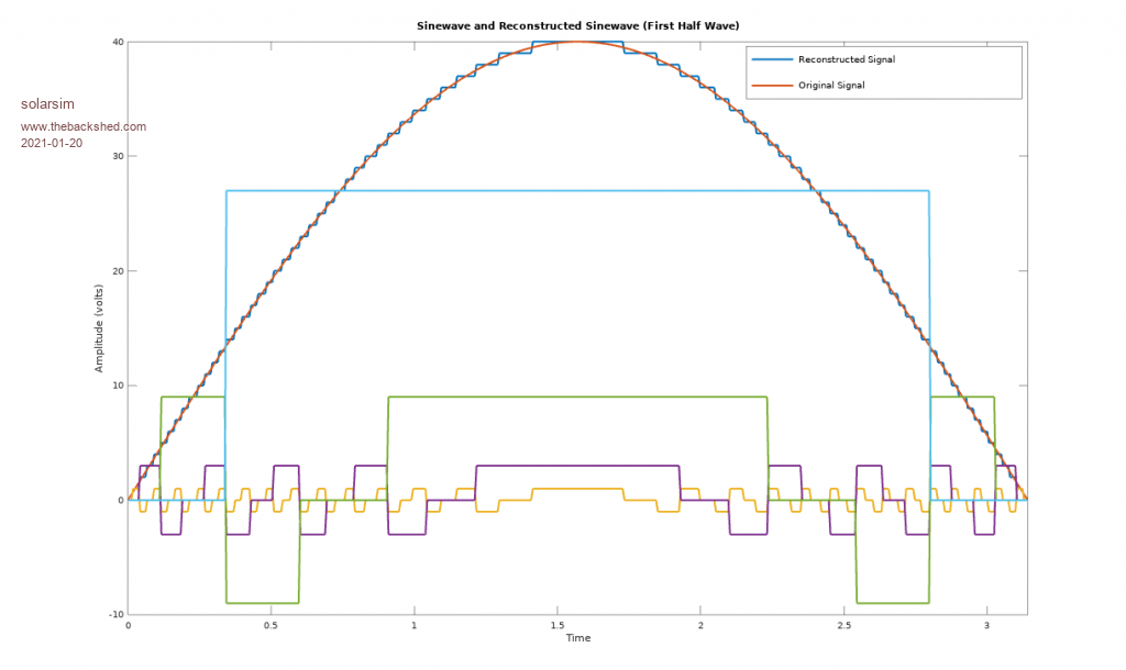 Is it a bad thing for a transformer drive signal to go straight from +1 to -1 without stopping at 0 (off) for a short while. ie % amplitude=9 (medium) transformer driven one way and then totally reversed without a bit of settling time? Should i hand edit the data to force a 0 state inbetween? thanks in anticipationjavascript:AddSmileyIcon('  ') ') |
||||
| Warpspeed Guru Joined: 09/08/2007 Location: AustraliaPosts: 4406 |
That diagram above is beautiful ! You have nailed it perfectly. Its the math and software that I find very difficult. The hardware part is much more my thing. A transformer can certainly transfer a square or rectangular voltage waveform without any problem at all. Its square wave current that transformers struggle with, but in the Warpverter, all the transformer windings only ever see a perfect sine wave current. If you can get to the stage of programming a suitable prom with multiple lookup tables, you are at least half way there. What I did was measure the dc input voltage with an eight bit analog to digital converter that begins at half scale. In other words X input volts give 00 and 2X input volts give FF That selects one of 256 different lookup tables. You can then jump from one lookup table to another at the zero crossing points without introducing any abrupt waveform discontinuities. That same prom will work over any 2:1 input voltage range, and all you need to do is wind your transformers to suit the minimum voltage the inverter will ever see. Edited 2021-01-20 17:13 by Warpspeed Cheers, Tony. |
||||