
|

|
Forum Index : Electronics : ozinverter control no sinewave
| Author | Message | ||||
| Tinker Guru Joined: 07/11/2007 Location: AustraliaPosts: 1904 |
Gary, I always thought the original 'reset' method was way too agricultural for my liking. What you suggest should be much more sensible to the workings. There is another way to reset, you may have spotted it in the schematic I posted some time ago. What I do is fit a N/C momentary push button in the positive lead to the SCR. This P/B switch also interrupts the input to SPWMEN. SPWMEN is, of course, always connected to ground via a 10K resistor so it is *never* open circuit. Klaus |
||||
renewableMark Guru Joined: 09/12/2017 Location: AustraliaPosts: 1678 |
Thanks mate, might be a good idea to put that on your pcb thread. Cheers Caveman Mark Off grid eastern Melb |
||||
Madness Guru Joined: 08/10/2011 Location: AustraliaPosts: 2498 |
I knew there must have been others who had another way to do this. The method I worked out today would give the same result but if the N/C switch was disconnected (which I know you would never overlook but others may) or contacts had failed you would never know till it is too late. My method does not interfere with the circuit in any way and when it is grounded it only draws a few milliamps. But it is certainly much nicer than the agricultural method as you described it. I feel very confident that this method is safe also has the 5-second delay after the reset so there is no possibility of it causing a dramatic glitch. There are only 10 types of people in the world: those who understand binary, and those who don't. |
||||
Madness Guru Joined: 08/10/2011 Location: AustraliaPosts: 2498 |
John that does not look right to me, the square should be very clean and crisp with virtually nothing other than the horizontal lines on the CRO. What I have done before is connect the 18VDC on a control board to the output of the 2 diodes from the VFB transformer near the centre of the of the PCB. You can then adjust the voltage trim pot till the EG8010 is happy with the feedback voltage and it will run with no power board. You can then use the square wave output to apply the square wave gate drive to the input of the power board gate drive circuits individually. There should be just an extremely faint line between the high and low of the gate signal. I have seen a full brightness line there which was a fault in the PNP half of the Totem poles. Should be like these. 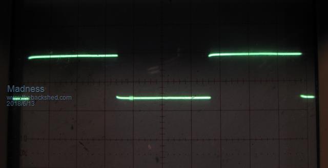 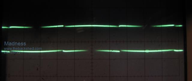 There are only 10 types of people in the world: those who understand binary, and those who don't. |
||||
| Tinker Guru Joined: 07/11/2007 Location: AustraliaPosts: 1904 |
Gary, it is failsafe. I have a remote switch box (it houses all the on/off switch & reset plus all the LED's) and if that is not plugged in at all nothing happens. You see, that permanent 10K to ground from the SPWMEN input (pin 6) stops all mishaps in case of switch or reset malfunction. Your last CRO pictures of the EG1810 wave form is exactly what I observe. That overshoot on John's pictures needs investigating, perhaps he has a few decoupling caps missing? BTW, When I did my control board I copied something I saw on the original EG002 boards. These had a 5K1 pulldown (to ground) resistor at each of the 4 SPWOUT pins (27-30) of the EG1810 chip. Not sure exactly what they do but the trace always looks good. Klaus |
||||
Madness Guru Joined: 08/10/2011 Location: AustraliaPosts: 2498 |
Interesting, those pull down resistors are not on here and I can't see a reason to add them, just ordered another 50 PCBs 5 minutes ago anyway. 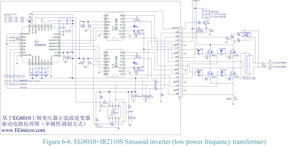 There are only 10 types of people in the world: those who understand binary, and those who don't. |
||||
| noneyabussiness Guru Joined: 31/07/2017 Location: AustraliaPosts: 513 |
The ir2110's have a internal pull down resistor built in... I think it works !! |
||||
| tinyt Guru Joined: 12/11/2017 Location: United StatesPosts: 438 |
Using a picture of the powerboard, where is the 'scope ground and 'scope probe connected for your pictures. |
||||
| Tinker Guru Joined: 07/11/2007 Location: AustraliaPosts: 1904 |
Correct. I was referring to this diagram: first page There are also interlocking transistors shown, which I did not include. Klaus |
||||
| Tinker Guru Joined: 07/11/2007 Location: AustraliaPosts: 1904 |
Well, your board seems to work anyway, I just wanted to mention what I did differently... 50 PCB's  , are you running a business there? I would not have thought that inverter bug being that contagious , are you running a business there? I would not have thought that inverter bug being that contagious  . .Its got me well and truly though, getting inverter#4 ready to put together  . .Klaus |
||||
| johnmc Senior Member Joined: 21/01/2011 Location: AustraliaPosts: 282 |
Good Day tinyt The scope pictures were taken with the 50v negative attached to the to the power board negative PCB rail and the 50v positive attached to the positive rail via the FET heatsink. The scope earth lead connected to the negative supply ( the scopes earth led is isolated from the 240vac scope supply The scope probe was connected to the inverter output, that would have gone to one side of the toroid , This hash is found on the control board output, with out the power board connected. A interesting note is that tonight , on initial start up there was no hash on the signal, with in a couple of seconds the hash had built up on the scope as shown previously scope shots. After a couple more of starts the hash was there all the time, this appears there is a faulty component/s on the control board. This problem has haunted me since february. In my efforts to find the component I shorted out the board hence no pic,s for awhile. Tomorrow I will be repairing my car,s automatic transmission shift solenoid , which has locked the transmission in 2nd and reverse fault mode. cheers john johnmc |
||||
Madness Guru Joined: 08/10/2011 Location: AustraliaPosts: 2498 |
I have sold 37 so far of the last lot of the big inverter boards. In my power house there are 2 Inverters one running the house and another connected up and ready to turn on with the flick of a few switches. There is a double stack of cores waiting to get wound for the next one. I will be putting as much copper on it as I can. However my main focus at the moment is writing software for the charge regulator. It is running very nicely but adding more functionality and refining it. I am very pleased with the hot water diversion, it is working much better than the commercial charge controller I have been using. It also much more Inverter friendly with the PWM to the SSR, runs at a higher frequency and the Inverter does not growl like when the commercial charge controller was in use. There are only 10 types of people in the world: those who understand binary, and those who don't. |
||||
Madness Guru Joined: 08/10/2011 Location: AustraliaPosts: 2498 |
John, have you tried removing the IR2110s and check the output from the EG8010? Sometimes the IC sockets can fail to connect properly which could easily be intermittent. Some pressure on the IR2110s might cause some change. There are only 10 types of people in the world: those who understand binary, and those who don't. |
||||
| johnmc Senior Member Joined: 21/01/2011 Location: AustraliaPosts: 282 |
Good Day All Managed to get the inverter up and running with a full complement of fets and capacitors and driving 4 kw of heaters The no load sine wave has a small oscillation 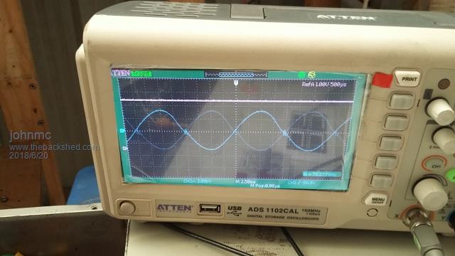 the enlarged view of the oscillation 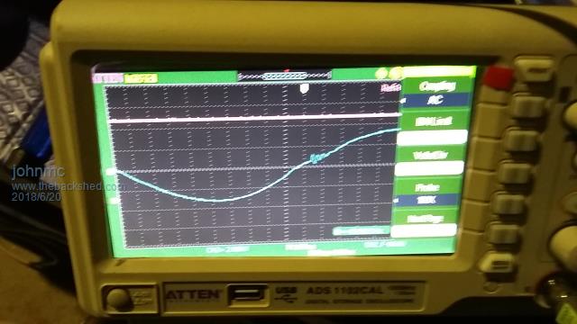 the transformer has very little noise under load from 1 kw to 4 kw the wave shape does not alter but it is not ideal either, could this wave form be because the transformer choke /inductance coil is only on one leg? 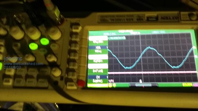 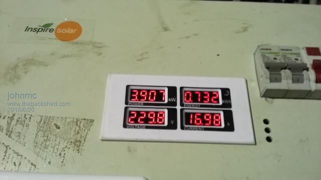 The over current SCR was reset as with out drama thanks madness. Having trouble shutting down the control board, at present the only save way for me is to disconnect the 48volt supply to the power board then the 14 pin plug from the control board. Have managed to blow all the fets twice now when I try to use my inverter welder which has a rating of 3.6kw. This is still a work in progress cheers john johnmc |
||||
Madness Guru Joined: 08/10/2011 Location: AustraliaPosts: 2498 |
Good to see you are making progress John, the choke only needs to be on left bridge as you look at it from the 10 pin connector side of the power PCB. That is the side with the 20KHZ SPWM, the other side is 50HZ square wave. The wobble at zero crossing is most likley to do with your choke, what are you using? The distortion at the peaks is something I have never seen before. Switching off should be no drama, the centre pin of the switch connector on the PCB is switched to 5V for on and to ground for off. Is there possibly a bad ground connection there and did you follow the mods required for the switch in the word document I posted? There are only 10 types of people in the world: those who understand binary, and those who don't. |
||||
| wiseguy Guru Joined: 21/06/2018 Location: AustraliaPosts: 1156 |
Hello All! This is my first post here - sorry in advance for being a bit verbose. I was looking for information on the EGS002 and found this site which is most impressive. If I have posted in the wrong place please shift it to where it belongs. I read quite a few posts about inverter mosfet failure & apologise if the following details have been raised before or even solved. Of course I havent read everything posted on this site by a long shot so may have missed it. I have been using FET's for over 30 years now and have some experience with an obscure FET instability that may be of use to some readers. Most of my applications have been Dc/Dc converters with synchronous mosfets as rectifiers with efficiencies in the high 90's up to 1Kw. I also created a computer controlled multiple battery charging systems for plate formation of new lead acid batteries at ~ 2Kw for each charger. These units were connected to 2000A 120V rectifier systems and there were 64 chargers in a standard single 19" rack unit (yes ~ 1,300A of controlled output). After reading of unexplained failures and distorted waveforms I felt I would share some of my experience with others on this forum. In my experience of paralleling Mosfets, oscillations can occur at the flattening part of the drive waveform at turn on (during the miller period). Mosfets would fail intermittently and regularly although there were 3 units in parallel, they did not seem to share the load equally & ran hotter than expected. The signal can be seen by probing directly to the gate or the drain ( both referenced to the source) using a 100MHz CRO, they are not usually visible when looking for sinewave distortion at 50 Hz, except maybe a "slightly thicker" gate waveform. It may also be necessary to use ac coupling for the drain signal and a resistive divider with suitable diode clipping to avoid over-driving the CRO channel, whilst searching for lower amplitude HF oscillations superimposed on a high DC level. At this point I think it best to direct you to Google App Note APT0402 for an excellent description of cause and cure. I hope this may be of use with explaining some of the occasional intermittent early demise of paralleled Mosfet banks. Now I have a question for others, I have not yet purchased the EGS002 board yet, as I only just discovered it so am not sure of their exact operation. There appears to be 2 methods of creating the HF transformer drive waveform for a 50Hz output. Case 1) All 4 legs of the H bridge fets can be switched with PWM HF waveforms where the LHS is modulated from 0 to Vin and back whilst the RHS fets operate in exact antiphase giving a total of Vin x2, P-P to the transformer. Case 2) just the LHS is PWM modulated from 0 to Vin and back again whilst the RHS lower FET/s are on continuously (first 180Deg), then the LHS lower FET/s is kept on whilst the RHS stage is modulated from 0 to Vin and back (last 180Deg). The Case 1 appears to have switching losses for the FET/s of all 4 legs of the "H", whilst case 2 has switching losses for just the switching Leg of 2 FET/s for the first 180Deg, then the other 2 FET/s for the next 180Deg. Can anyone confirm that this has been tried and Case 2 would be more efficient than Case1 ? If at first you dont succeed, I suggest you avoid sky diving.... Cheers Mike |
||||
| wiseguy Guru Joined: 21/06/2018 Location: AustraliaPosts: 1156 |
Another quick question, the EGS002 can be interfaced to a 12832 display, their suggested circuit has 5 connections. Most of the boards I have found only use 4 - they dont use the CS/Enable input. apart from power and ground they just have serial clock and data. Will just the 4 connections work or do i need to figure out the missing connection ? Thanks in anticipation. If at first you dont succeed, I suggest you avoid sky diving.... Cheers Mike |
||||
| johnmc Senior Member Joined: 21/01/2011 Location: AustraliaPosts: 282 |
Thanks for the info Gary, The transformer choke is on the 20KHZ side as per last post. I replace all the fets on the high side . The control board was not affected connected the on off switch as per you post. Tested the repaired power board all systems go, on off switch works SCR switch works with 5 kw load . Connected to the solar system still working. THEN over current light came on, SCR switch cancelled over current light. load removed from inverter no response from inverter Switched 48v supply off removed 10 pin connector waited till no response from EG001 light, replaced 10 pin connector With on the on off switch off, turned the MCB on Bang once again all the high side fets blown. A commercial inverter is starting to look good, cheers john johnmc |
||||
Madness Guru Joined: 08/10/2011 Location: AustraliaPosts: 2498 |
@Wiseguy, thanks for your input I will have a good read of the App Note later, Ferrite beads are used in the Chinese Inverters I believe. I have some in my box of parts but not used them for a long time. I am using a Totem pole gate driver and getting very good results with 6 HY4008W MOSFETs in Parallel. Prior to using the Totem Poles, I had lots of problems with more than 4 FETs in parallel. We are using your case 2 which is called Bipolar mode in the EG8010 manual for fixed frequency. If you want variable frequency you then need to go to your case 1 or Unipolar Mode. @John, something is wrong with the on-off switch, it should not give trouble like that. Whatever it is probably is causing your grief. With no switch connected and the 10K pull-down resistor in place as suggested by Tinker the Inverter does not run. The switch circuit is easily effected, my Inverter started restarting with rapid switching of my HWS element via PWM from my charge regulator. Even though the wire is only 80mm long and shielded it was looping back towards the heatsinks. I moved it far away from the heatsink as far as possible and it stopped the restarting issue. It is frustrating to hear your difficulties with this, I struggled with it for a long time also if you read through my build thread much of that is documented there. But once I starting using the Same power board circuit as you have now my problems went away. I have assembled 3 of the same control boards as you have and one small power board and the same big power board as you have and they worked right away and are is still running with the only hiccup since fixing the couple track error on the control board around the on-off switch. Is there any chance that there is still some copper from the cut tracks still making a connection on the control board? 2018-06-22_072220_MAD_CONTROL_BOARD_MODS_REQUIRED.zip There are only 10 types of people in the world: those who understand binary, and those who don't. |
||||
| yahoo2 Guru Joined: 05/04/2011 Location: AustraliaPosts: 1166 |
Hi wiseguy, to be honest the esg002 board is a bit of a mixed bag, some are poorly put together and components are not always the appropriate ones. if you are prepared to resolder stuff and swap out some caps for low esr units and go over the board with a practiced eye you will be OK. I dont have years of experience and they were quite painful to work with. One of the reasons we moved on to the eg8010 module and copied John's (oztules) design, all the stuff ups now are our own making  ..... mostly . ..... mostly .there might be some info about the display communications here anotherpower.com oztules user journals I'm confused, no wait... maybe I'm not... |
||||