|

|
Forum Index : Electronics : 6Kw Ozinverter build
| Author | Message | ||||
oztules Guru Joined: 26/07/2007 Location: AustraliaPosts: 1686 |
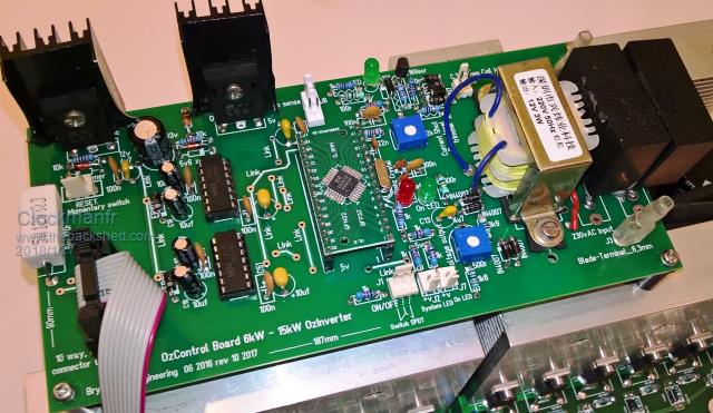
Notice the word HOT on the sinks..... this is the one that will heat up the most under heavy load.... so it is to remind me to put the fan at that end... It rarely gets over 40c in practice.... so keep that in mind when designing your cooling, it is the spwm end of the board, the other end is 50hz. ......oztules Village idiot...or... just another hack out of his depth |
||||
| Tinker Guru Joined: 07/11/2007 Location: AustraliaPosts: 1904 |
Have you got a reason why this one should heat more than its neighbor? Might be worth while to choose that one to mount the NTC sensor on too if that is so. Klaus |
||||
| Tinker Guru Joined: 07/11/2007 Location: AustraliaPosts: 1904 |
Another tip Mark, plug both of the SIL carrier strips to the little 8010 board and solder it to the control board as a unit. This keeps both SIL sockets lined up correctly. If you solder them individually they might end up a little sideways and make plugging in the little board much harder. Klaus |
||||
oztules Guru Joined: 26/07/2007 Location: AustraliaPosts: 1686 |
"Have you got a reason why this one should heat more than its neighbor? Might be worth while to choose that one to mount the NTC sensor on too if that is so" Yes Tinker, that is the one I use for the temp sensor. It is the SPWM end, so the switching losses are higher than the 50hz end. The high side should be worse, but isn't, and shares the heat sink with the colder high side 50hz.... sorta averages out I guess. The drive signal on the high side seems to be so good as to be about the same losses on both the high and low sides. So the smallest heat sink with the highest frequency gets warmer than the other three quadrants. Once the fan system is installed, it rarely gets much over 40c, unless your really driving it hard, but that is generally for short periods ( 10 mins or so ). Unusual to run more than 4kw for extended periods.... unless your backfeeding from a big GTI. Periods extended over 5kw will activate the 20amp breaker after a time interval governed by the breaker curves. They are pretty generous, but 8kw for more than a few minutes can trip it. ........oztules Village idiot...or... just another hack out of his depth |
||||
| Clockmanfr Guru Joined: 23/10/2015 Location: FrancePosts: 429 |
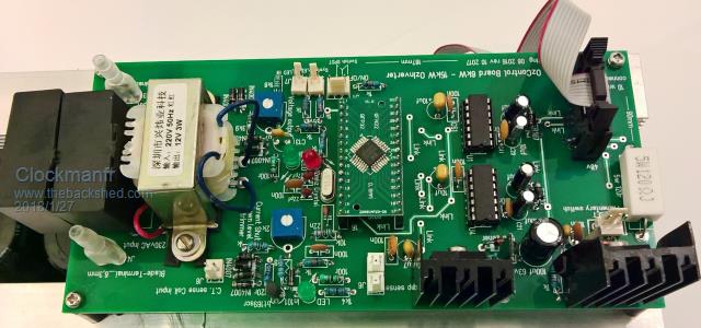
Hi Mark, Here is a link to the latest boards that are all component populated. http://www.echorenovate.com/the-ozinverter.php Trust this helps.   Everything is possible, just give me time. 3 HughP's 3.7m Wind T's (14 years). 5kW PV on 3 Trackers, (10 yrs). 21kW PV AC coupled SH GTI's. OzInverter created Grid. 1300ah 48v. |
||||
renewableMark Guru Joined: 09/12/2017 Location: AustraliaPosts: 1678 |
Thanks for the tips guys and the better pic Clockman. Cheers Caveman Mark Off grid eastern Melb |
||||
| Warpspeed Guru Joined: 09/08/2007 Location: AustraliaPosts: 4406 |
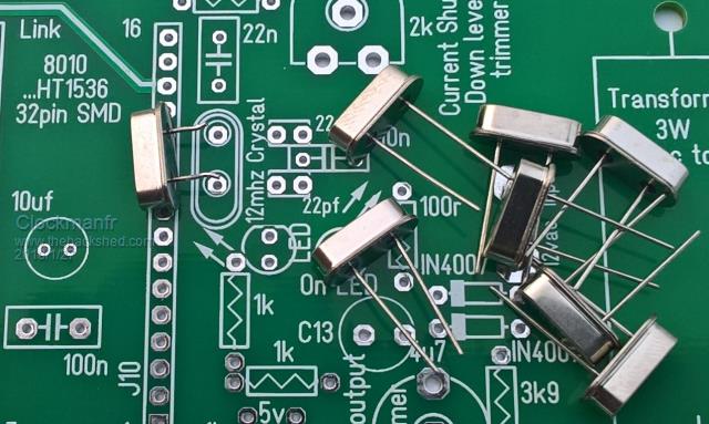
[quote]...oh, and make sure there is clearance for the crystal above the board ( say 1mm air gap )[/quote] This may seem like a very minor point, but it is not. The metal can of the crystal can quite easily short to the two pads underneath if there is zero clearance, and that would cause an instant major inverter mosfet blow up if it ever happened, without the cause being obvious. There are special crystal isolating insulators available on e-bay, or use a pair of really tiny fiber or plastic washers, or punch a couple of pin holes through an insulating sheet of "something". It may save a lot of tears. Cheers, Tony. |
||||
| Clockmanfr Guru Joined: 23/10/2015 Location: FrancePosts: 429 |
Yes Warpspeed is correct. Be careful with the crystal can when installing. The can package to legs insulation is small and could easily short to a leg wire solder pad. As this is a via pin on both sides of the board, reducing the diameter could lead to a weakness with the pad and substrate. And solder flows and does a neat upwards cone around the wire legs. A Moisture installation environment could be issue with the OzInverter, and I have done wide spaced out tracks to elevate this, with reasonably free space around each component. I tend to have the can positioned with 1mm to 1.5mm above the board, ie the crytall legs can take the load of the can weight. See photo of crystal can legs length, that one has ben removed from a previous PCB board.  Everything is possible, just give me time. 3 HughP's 3.7m Wind T's (14 years). 5kW PV on 3 Trackers, (10 yrs). 21kW PV AC coupled SH GTI's. OzInverter created Grid. 1300ah 48v. |
||||
renewableMark Guru Joined: 09/12/2017 Location: AustraliaPosts: 1678 |
Thanks guys, keep the tips coming. I got the second layer of 128 on today, wow HF it goes on so much easier on a hot day. It was 35c here today and the copper just flowed off the spool like fishing line. Too late and tired to do the volt test with the light, then short light procedure. Just a question, lets say the phasing was incorrect, what would the outcome be? I'm sure mine are ok as I have bent the start at the top and the finish at the bottom, but it would be good to know the result of a wrong phase connection. Cheers Mark Reckon I owe you bastards a few beers if you ever pop around. Cheers Caveman Mark Off grid eastern Melb |
||||
Madness Guru Joined: 08/10/2011 Location: AustraliaPosts: 2498 |
Only outcome will be bad readings and a few four letter words, unless you touch something you shouldn't. If you got it arse about face you will get reading of 480 volts across the 2 ends. If it reads 0 you can say you jump around and scream with joy like your kid. I won't be visiting Melbourne any time soon, but your welcome to drop in if your up this way. There are only 10 types of people in the world: those who understand binary, and those who don't. |
||||
renewableMark Guru Joined: 09/12/2017 Location: AustraliaPosts: 1678 |
Awesome I can come and drink all your grog then...... ripper!! Thanks again. Cheers Caveman Mark Off grid eastern Melb |
||||
Madness Guru Joined: 08/10/2011 Location: AustraliaPosts: 2498 |
No problem after you have done a days work :) There are only 10 types of people in the world: those who understand binary, and those who don't. |
||||
renewableMark Guru Joined: 09/12/2017 Location: AustraliaPosts: 1678 |
OK all went well. Set up the common connection (Neutral) and tested 237.2v to both loose ends from the common connection, it did vary up and down .1 and .2 must have been some draw from appliances in the house??? Dunno, but it settled back to 237.2 each time it fluctuated. The voltage between the two loose ends was .1v dunno why it wasn't zero. Clamp meter was .067A on the active line going to the torroid. So 16w, pretty happy with that! Time for 20 beers, it's hot today 39c. Cheers Caveman Mark Off grid eastern Melb |
||||
| Warpspeed Guru Joined: 09/08/2007 Location: AustraliaPosts: 4406 |
[quote]The voltage between the two loose ends was .1v dunno why it wasn't zero. Clamp meter was .067A on the active line going to the torroid. So 16w, pretty happy with that![/quote] Very well done, a splendid effort Mark. Cheers, Tony. |
||||
renewableMark Guru Joined: 09/12/2017 Location: AustraliaPosts: 1678 |
Thanks mate. even a knucklehead like me can do it. Cheers Caveman Mark Off grid eastern Melb |
||||
Madness Guru Joined: 08/10/2011 Location: AustraliaPosts: 2498 |
Good job you have earned a beer or 2. There are only 10 types of people in the world: those who understand binary, and those who don't. |
||||
renewableMark Guru Joined: 09/12/2017 Location: AustraliaPosts: 1678 |
Thanks Mad, forgot to say as you suggested I left an extra metre of copper when winding the second coil. Just to make sure I used that extra metre and wound it through the torroid one more test turn, it produced 239v, so that confirmed the initial turn count was correct. Time to glue the frigga up and do another winding tomorrow, too hot to work outside now. BTW when testing the third winding it's done the same right? Common neutral connection and test between that and the loose ends. BTW thanks for talking me into doing this Mad, it's been a fun project! Cheers Caveman Mark Off grid eastern Melb |
||||
renewableMark Guru Joined: 09/12/2017 Location: AustraliaPosts: 1678 |
Is that 0.1v across the two loose ends anything to worry about? Cheers Caveman Mark Off grid eastern Melb |
||||
Madness Guru Joined: 08/10/2011 Location: AustraliaPosts: 2498 |
0.1 would just be the resistance in the wire I think, just finish that wire and get ready to the same with the next one. All I need to do now is convince you that adding a GTI is a good thing. With this hot weather, I have 2 AC's running total load on the AC circuit is around 6KW most of the day. My GTI is producing 4KW so the off grid inverter is only having to make 2KW. As the container where the inverters and battery are is air conditioned the fans on the inverter are not even starting up. There are only 10 types of people in the world: those who understand binary, and those who don't. |
||||
| Warpspeed Guru Joined: 09/08/2007 Location: AustraliaPosts: 4406 |
Yup. Rinse and repeat. Don't worry about the 0.1 mystery volt its way smaller than one full turn of error, or getting the whole second winding arse about, which is all we need to know. Cheers, Tony. |
||||