|

|
Forum Index : Electronics : OzInverter OzCntrl PCB rev12 Sept2017
| Author | Message | ||||
oztules Guru Joined: 26/07/2007 Location: AustraliaPosts: 1686 |
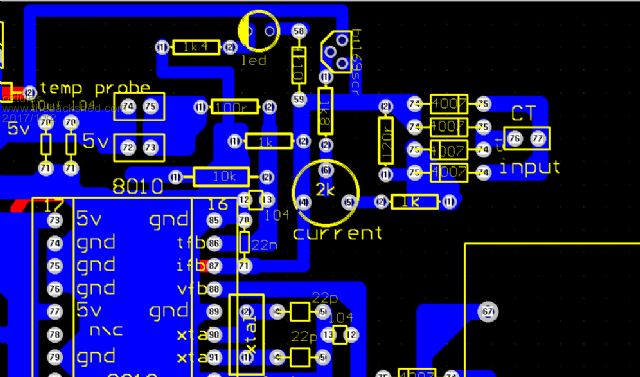
" What disturbs me is that it can not be reset without physically switching main power off. " I just press the momentary reset. You don't need to power down. Shorting the 120r to ground zero's the 5v and everything else, releasing the switch, the 5v recovers very fast, the 8010 soft starts. It is designed to soft start from zero volts. The reset momentary switch has been triggered under all circumstances, and the result is the same.... perfect restart. This chip is designed for this kind of nonsense, as it is after all designed to run on the tail end of a tl494 voltage step up system. It has no reset , as it was never intended to be anything other than slave driven by the availability of voltage or not from my reading of it. Here is my board's current sensing part.  I'm not an electronics engineer, just the village idiot, and would not know what a ground plane was if it popped up in my porridge... but I can make most things work as a general rule. ...........oztules Village idiot...or... just another hack out of his depth |
||||
| noneyabussiness Guru Joined: 31/07/2017 Location: AustraliaPosts: 513 |
I was just going to add, the lights on all my 8010 chips continue to flash.. even after turning off the switch of there was a fault (over temp etc.) Also on a side note, if you ground the " VS " pin on the ir2110 you can observe the "high side " waveform... just remember to disconnect it before hooking it up to main board.. I think it works !! |
||||
| brac321 Regular Member Joined: 30/11/2016 Location: SloveniaPosts: 54 |
Thanks Oztools, looks like I have properly wired components around SCR. And thanks for all explanations. Have you measured what voltage is there on CT input at 9 or 10kW power ? OffGrid 24/7: 250w black mono solar panels 6.4kWp, 1x Midnite Classic 150, 1x MorningStar MPPT 60, battery bank 840 Ah @ 48v, modified LF-8K inverter, DC/DC, hot water harvesting, etc. |
||||
oztules Guru Joined: 26/07/2007 Location: AustraliaPosts: 1686 |
"Have you measured what voltage is there on CT input at 9 or 10kW power ?" No I have not bothered to do so..... I am only interested in where it triggers, and that will be coil and shunt dependent.. At the moment I am using 2000t coil, which is way too big, but makes no difference with a shunt across it. If your coil has less turns, then the components may change if the trimmer is out of range. ( 120r may need to be bigger or smaller) Minimum trigger is about 4kw and goes up from there with my coil and those component values. You look close to success. .........Oztules Village idiot...or... just another hack out of his depth |
||||
| brac321 Regular Member Joined: 30/11/2016 Location: SloveniaPosts: 54 |
The coil I intend to use is DL-CT08CL5 OffGrid 24/7: 250w black mono solar panels 6.4kWp, 1x Midnite Classic 150, 1x MorningStar MPPT 60, battery bank 840 Ah @ 48v, modified LF-8K inverter, DC/DC, hot water harvesting, etc. |
||||
| Clockmanfr Guru Joined: 23/10/2015 Location: FrancePosts: 429 |
Yes that 2000 to 1 is good as most size cables will go through it. On my Big Ozinverter I have a larger 2000/1 but with a bigger hole as I have a 16mm/2 going through it. Oztules 2000/1 design and the corresponding value components works well. Everything is possible, just give me time. 3 HughP's 3.7m Wind T's (14 years). 5kW PV on 3 Trackers, (10 yrs). 21kW PV AC coupled SH GTI's. OzInverter created Grid. 1300ah 48v. |
||||
| Clockmanfr Guru Joined: 23/10/2015 Location: FrancePosts: 429 |
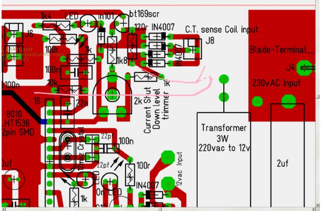
Hi Oztules, Reset momentary, .... something like this. I think I have the right end of the 120r? 50/50 chance haha.  Everything is possible, just give me time. 3 HughP's 3.7m Wind T's (14 years). 5kW PV on 3 Trackers, (10 yrs). 21kW PV AC coupled SH GTI's. OzInverter created Grid. 1300ah 48v. |
||||
oztules Guru Joined: 26/07/2007 Location: AustraliaPosts: 1686 |
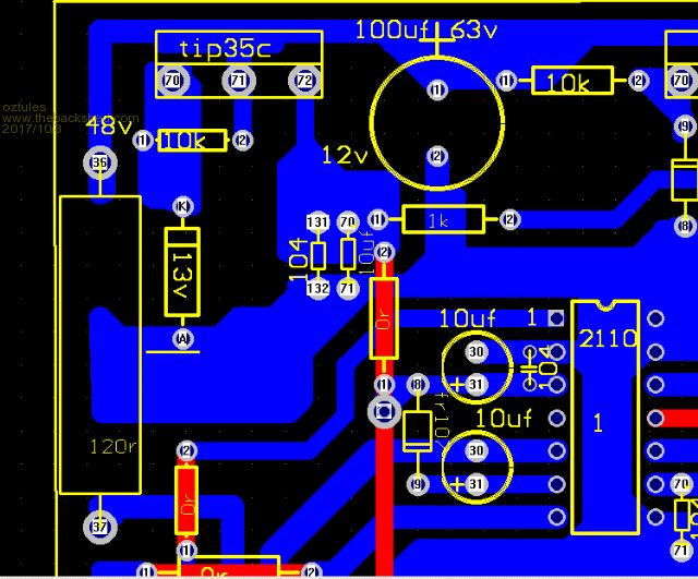
No Clockman... the 5w one on the input rail  If you look at pin labelled as 36, it is there I short to ground momentarily. It's a bit rough and ready, but gee it's effective. Do NOT do it from 37.... thats a direct short to ground... not a good look. It restarts immediately, but a very soft start is assured. It stops it hanging from slow charge up ( what I mostly use it for ) but also recovers from over current conditions perfectly. Even if you press it while running 6kw..... no problem, just restarts and drives the 6kw load as it comes on. It really is neat. "I think I have the right end of the 120r? 50/50 chance haha."... not quite in the same post code... so no cigar  ..........oztules Village idiot...or... just another hack out of his depth |
||||
| Clockmanfr Guru Joined: 23/10/2015 Location: FrancePosts: 429 |
oh crikey, totally wrong 120r.  I did wonder, why not on the 48v input, then as you say the 8010 takes some abuse, but not that much. Okay, will add a small board mounted momentary switch at that pin 36 area. Nice to have, That's if you think its worth the hassle? Everything is possible, just give me time. 3 HughP's 3.7m Wind T's (14 years). 5kW PV on 3 Trackers, (10 yrs). 21kW PV AC coupled SH GTI's. OzInverter created Grid. 1300ah 48v. |
||||
| Warpspeed Guru Joined: 09/08/2007 Location: AustraliaPosts: 4406 |
[quote]As he says, ..... "The one drawback with the 8010, is that if the voltage rises slowly, the chip will hang... and be totally unresponsive, so it needs a reset switch.[/quote] Oh dear, another likely problem to deal with. I have not yet noticed this effect, just lucky I guess. But now you have me worried. Small postage stamp switching power supplies with soft start powering this might give unreliable start up. It should be possible to add a small circuit that hard switches the +5v on (and off) very fast once the incoming voltage rises above some threshold very close to 5.0v. Give the wee beast a real kick in the pants. Cheers, Tony. |
||||
oztules Guru Joined: 26/07/2007 Location: AustraliaPosts: 1686 |
Clockman.... ... not really.....it is best to have a press button on the external surface of the box. Mine is under the unit ( wall hung ), so is not obvious, but easily available. This allows easy soft cap charge, and simple reset to start after that. Ideally, you would have a two pin connector on the board..... I just solder a few wires on at the moment. Once running will never be needed again, unless you overload extremely, then you want..... a reset button  . .No Warp, it is not even remotely worthwhile complicating a simple system. A push button is all thats needed, and all the folks who have these things over here, probably don't know the switch is even there ( it is labeled as reset on bottom), but it will never probably be be required. The on/off is also on the bottom, but who wants to turn off their power ( other than experimenters) Hanging is only probable if you don't want to splat the terminals on installation. After that, it is not likely to ever be required again except for current reset. In normal installations, the batteries are not disconnected again until refit.... once again a reset button is all thats needed. Here is a pic from another thread that shows the switch label/s .........oztules Village idiot...or... just another hack out of his depth |
||||
| Tinker Guru Joined: 07/11/2007 Location: AustraliaPosts: 1904 |
Well oztules, perhaps its the way you describe the workings of the VFB that has, at least for me, caused confusion. That part in particular: "provides the three volts there by massaging the output" 'provide' is perhaps a poor word choice. The 3 Volts must come from the rectified transformer 12V secondary, otherwise we would not need that transformer in the first place. In my understanding the primary of the toroid gets manipulated by the 8010 chip to put out the desired secondary AC voltage. This AC powers the little 12V tranny which in turn feeds the VFB control to maintain the VFB pin at 3 volts. *no* voltage comes out of the VFB pin, its a feedback circuit as you said. Perhaps you have not blown up as many Mosfets as I have  but I can tell you one gets nervous connecting *any* transformer to them before making quite certain all the driving components run faultlessly. but I can tell you one gets nervous connecting *any* transformer to them before making quite certain all the driving components run faultlessly.And that can only be done by feeding somewhere between 2.5 & 3VDC into the VFB pin. The idea is to get the 8010 to start & keep running and it does not matter, when observing the wave forms, if the VFB is working in feedback mode or not. I can then see if the 8010 puts out the correct wave form on all pins or, perhaps, one is missing, indicating the chip is kaputt. Further down the line I can check if these wave forms are arriving at the IR2110 drivers. Then checking the outputs of these drivers, the high side can be seen clearly on the cro using the probe adapter described on the EG002 data sheet. I certainly found faulty driver chips by that method. Next comes checking if the drive pulses arrive at the mosfet gates. Then, and only then, if all checks out OK, do I connect the toroid and power up the 48V rail. This may sound all odd to an inverter expert like yourself but, believe me, its a safe way to weed out faulty components without even to have the 48V power present on the board. That I learned by bitter experience. You wrote: "and you will get a proper picture of the wave forms, as they will be real, rather than trying to fight against a fixed wrong voltage." Which is a bit of a contradiction IMO as a fixed VFB voltage tells the 8010 chip all is well, please continue outputting wave forms for that level. Surely, you agree that the VFB voltage feedback on a working inverter does not have to be constantly doing the 'feedback' thing if the AC output is steady? Which is equal to the fixed voltage feedback during testing, no 'fighting' involved at all. So, please do not knock what some consider an essential way of initial testing. At least for those who do not manage to create a perfectly running inverter at the first try. Klaus |
||||
oztules Guru Joined: 26/07/2007 Location: AustraliaPosts: 1686 |
Tinker, your welcome to do whatever you wish. It is something I did once too, until I realized it was just stupid... so I don't do it any more. I have given you a safe procedure to test your setup, and you cant blow up the fets if you don't have energy storage, and you have a current limited 48v supply. They are 200 amp fets, and will not blow up with a limited supply and no caps, no matter the wave forms. Any deviation from center will give you distended waveforms, or compressed, and you will not see all the interactions going on at all levels at all places in real time.... learning will be limited. This is when all parts can be studied, and you will learn fully what is going on and why. You can test all aspects of the inverter without fear of fet failure, check your waveforms... ground out gates to see what happens....everything safely. I definitely don't advise the course of action you are presently taking, and which I also once took. It is of very limited use, and I don't do it anymore, nor condone it as the best way to see whats going on.... the best way to see whats going on... is to see whats going on for real.... but with no caps any where in sight and current limited. If you have a noisy fet or worse, your way will probably not find it until you hook it up for real, thinking the waveforms are right... and they are, but it still blows up. We will have to agree to disagree on this one. It is true I build them now in a day or so, and just turn them on and they work..... but that has more to do with having only 2 boards, and so no way to mess it up, but I still do the no caps test just to be sure. Paint by numbers takes the skill out of it.... I like it. ........oztules Village idiot...or... just another hack out of his depth |
||||
| Clockmanfr Guru Joined: 23/10/2015 Location: FrancePosts: 429 |
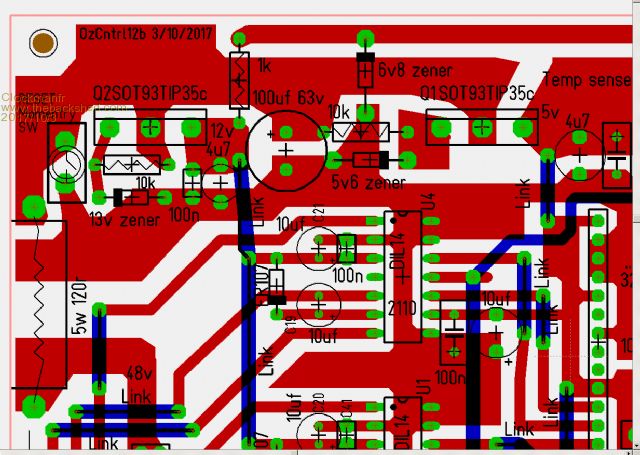
Okay Oztules have amended latest board. As you can see it gives the option of on the board Switch. keeps my little rascals from messing if its inside, or a 3 pin molex connector, just snip of the canter leg on the male molex pins.  Got lots of different small momentary switches. Everything is possible, just give me time. 3 HughP's 3.7m Wind T's (14 years). 5kW PV on 3 Trackers, (10 yrs). 21kW PV AC coupled SH GTI's. OzInverter created Grid. 1300ah 48v. |
||||
| Clockmanfr Guru Joined: 23/10/2015 Location: FrancePosts: 429 |
Warpspeed, I have never noticed or ever needed a Reset, but then I am naughty using that 250amp DC breaker, sometimes it goes a big PHUT noise on re connecting the DC/batteries. Like Oztules, once the Inverter is running switched on and off for testing, then check see for a few days, then they stay pretty well on permanently. I just don't have the time to mess about to much, and nowadays if it runs and behaves and does what I wants, then I am not poking a metaphorical stick into it. Everything is possible, just give me time. 3 HughP's 3.7m Wind T's (14 years). 5kW PV on 3 Trackers, (10 yrs). 21kW PV AC coupled SH GTI's. OzInverter created Grid. 1300ah 48v. |
||||
| Warpspeed Guru Joined: 09/08/2007 Location: AustraliaPosts: 4406 |
I have not either, but I suppose it depends where the dc power comes from. With lower battery voltage, probably straight from the battery via a linear regulator of some kind. Bench testing with a typical bench power supply is not likely to be a problem either. For higher battery voltages (>100v) its more likely to be a Chinese switching power supply that may have a very soft start up characteristic. That is how I will be doing it. As far as slowly bringing back to life a dead inverter, or with something totally new and untried, "slowly slowly catchee monkey" is the safe way. I have a test box for testing gate driver chips and mosfets. A 555 timer causes some LEDs to wink on and off. Or maybe not if something has died. Then check all the drivers without mosfets fitted by feeding +3.0v into Vfb. Next test is with mosfets but no transformer. And lastly transformer, series resistor, and no big electrolytic. All this only takes a very short time to do with a bit of practice and its totally safe. The problem is that after a major blow up there may be multiple dead components, ALL of which need to be replaced, or it will just keep blowing up. It takes maybe ten minutes to go through the whole pedantic routine. Nothing worse than blowing up the very last part you have. Cheers, Tony. |
||||
oztules Guru Joined: 26/07/2007 Location: AustraliaPosts: 1686 |
"The problem is that after a major blow up there may be multiple dead components, ALL of which need to be replaced, or it will just keep blowing up." I designed this inverter to be silly easy to fix after going nuclear. It has plug in drivers and easy to access fets. No matter what has happened, it only requires new fets and plug in two new drivers, and it will be as new. Before I put in the 120r input resistor, the tip could be drowned as well, but has never happened after the 120r and cap went in... so only drivers and fets. If you use 130amp breakers, you will have no board damage, and probably never get to blow the drivers either. Also, you end up only killing one set of fets ( a high and low set)... If you use big fuses, you will likely kill both H bridges, and drivers, and damage the boards. ...........oztules Village idiot...or... just another hack out of his depth |
||||
| Warpspeed Guru Joined: 09/08/2007 Location: AustraliaPosts: 4406 |
Absolutely ! Plug in drivers to protect the IR2110 And screw terminal blocks for the mosfets Change everything with known working parts, then test the survivors later. Cheers, Tony. |
||||
Madness Guru Joined: 08/10/2011 Location: AustraliaPosts: 2498 |
Just stopped for lunch. all MOSFETs blew, the low side drive transistors and the power supply circuit. Control board was uneffected, but this is different to Oztules design. I have run it with 4 FETs and no problems, ready to test now with all fets in place before adding the capacitors. There are only 10 types of people in the world: those who understand binary, and those who don't. |
||||
| Clockmanfr Guru Joined: 23/10/2015 Location: FrancePosts: 429 |
Would be nice to have a test box. Is it complicated? At present I test the FET's as per the standard Internet advice way. Everything is possible, just give me time. 3 HughP's 3.7m Wind T's (14 years). 5kW PV on 3 Trackers, (10 yrs). 21kW PV AC coupled SH GTI's. OzInverter created Grid. 1300ah 48v. |
||||