
|

|
Forum Index : Electronics : time to build a replacement inverter
| Author | Message | ||||
renewableMark Guru Joined: 09/12/2017 Location: AustraliaPosts: 1678 |
Ben the red control board Mad designed uses an 8010 to do the sine but also has a nano to customize charge settings and fans. My house has run for the last 3 months with the Mad power board and nano control board. The wife has thrown everything at it. Prior to that it ran for months with the Mad control card. Cheers Caveman Mark Off grid eastern Melb |
||||
| poida Guru Joined: 02/02/2017 Location: AustraliaPosts: 1418 |
Mad, here are the results of the 'splosion. High side FETS 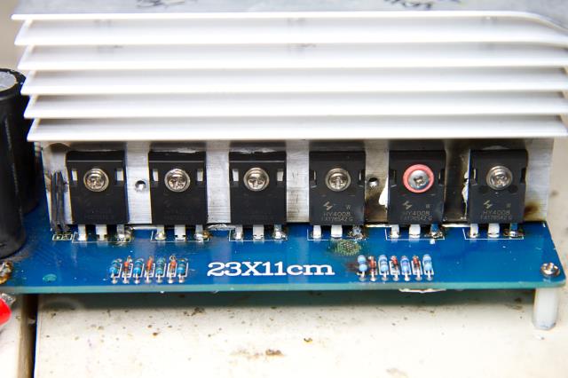 Low side FETS. 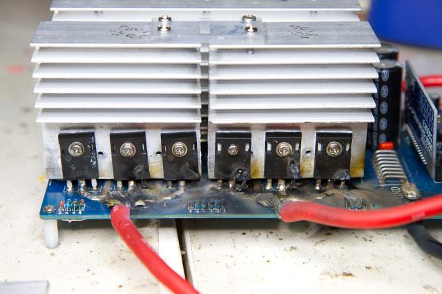 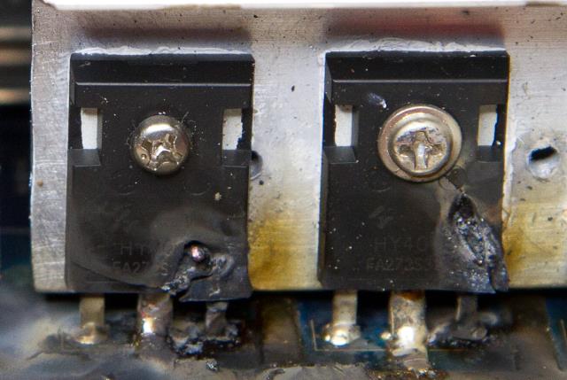 Anyway, I just got my spare Mad power board assembled and tested. It did not work! Lucky I only had one capacitor installed, else we'd have more photos of destruction. The reason it did not work was due to a redundant component lead hole that is near R36. 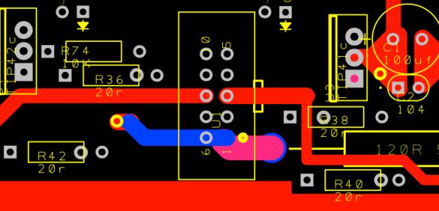 See R36? There is one hole for a lead on the left and there are 2 holes for a lead on the right. I fit the 20R resistor using the closest holes, that is, the inner hole on the right. This is a trap for the unwary. As it happens this is not the only component where there are these unneeded and confusing extra holes. To anybody building one of Madness's larger power boards, look carefully at these footprints and pin holes for all 4 of the 20R resistors. Make sure you have a clear understanding of which pins need to be soldered and which are to be left unused. It could so easily have blown all 12 FETS, certainly blown 6 if I had fitted any more capacitance. Anyway, once I refit R36 properly, it lives! Ben And Amber: please contact me before you start assembling your board. There are a couple of other things you best be aware of. wronger than a phone book full of wrong phone numbers |
||||
| BenandAmber Guru Joined: 16/02/2019 Location: United StatesPosts: 961 |
I will definitely get ahold of you poida the great If there is some way you could take a picture of the front and the back of your board I would just do mine exactly like yours that way maybe I don't question you and bug you to death or however you feel I should do it Whatever you say to do is absolutely awesome and great to me And I really appreciate your time be warned i am good parrot but Dumber than a box of rocks |
||||
Madness Guru Joined: 08/10/2011 Location: AustraliaPosts: 2498 |
That's a "PROPER JOB" on those FETs, well done  Those extra holes in the PCB are there if you wanted to bypass the totem poles. By putting a link in the two closest holes and another across the tip41 and tip42 emitters the gate drive is direct. It's a left over from the early days when I was trying to figure out why I was blowing up so many MOSFETs. If I get any more made it will be eliminated. There are only 10 types of people in the world: those who understand binary, and those who don't. |
||||
| Tinker Guru Joined: 07/11/2007 Location: AustraliaPosts: 1904 |
Yes, the tiny 2 internal source wires got overloaded and caused meltdown. I had exactly the same looking mosfet faces when testing how much they can stand  Klaus |
||||
| BenandAmber Guru Joined: 16/02/2019 Location: United StatesPosts: 961 |
How is things coming along poida the great be warned i am good parrot but Dumber than a box of rocks |
||||
| nickskethisniks Guru Joined: 17/10/2017 Location: BelgiumPosts: 458 |
Just thinking, I have 2 transformers out of my broken victron Phoenix 24V 3000VA inverter. I wanted to sell it for parts. But could I put primaries in series and secondaries in parallel for 48V? They could make a little spare/test inverter. |
||||
Madness Guru Joined: 08/10/2011 Location: AustraliaPosts: 2498 |
Then it would be a real Phoenix! There are only 10 types of people in the world: those who understand binary, and those who don't. |
||||
| poida Guru Joined: 02/02/2017 Location: AustraliaPosts: 1418 |
Nicks, I also had a blown 3000VA Victron inverter. It was a 48V Multiplus (that is, it had the charger installed). The inverter used 2 small toroids, and I suspect it powered one only when driving small loads, then powered both for larger loads. The toroids from my Victron were good things, actually. If possible, you should try to salvage them intact. I damaged one of them when extracting the inner resin mounting blob. A poorly aimed blow of a hammer broke a primary winding wire turn. My inverter was 48V, so they both had primaries suitable for 48V DC inverter (say 48V / 1.414 * (some factor less than 1)..) I think you will find your toroids from the inverter will have secondary and primary windings arranged such that they both occupy a small angle of the 360 degrees of the toroid. This is to create a large leakage inductance. You might notice that there is no large inductor in the primary winding. This is by design. For testing, the two toroids are perfect. You can experiment with parallel wiring, etc. I found the toroids from the Victron run with quite low core losses. wronger than a phone book full of wrong phone numbers |
||||
| nickskethisniks Guru Joined: 17/10/2017 Location: BelgiumPosts: 458 |
Thanks, yes the primary is wound on a rather small part of the toroid. What I don't get is why they switch a second toroid during higher load? The secondaries were connected parallel, no Relay or whatsoever in between( that I saw), so it's only the electronics that are saving power. I didnt know one side was blown, until I opened it for cleaning. No need for extra inductor? |
||||
| poida Guru Joined: 02/02/2017 Location: AustraliaPosts: 1418 |
I think there is a relatively large loss in the primaries of the two toroids. Instead of the 35 or 70mm2 windings we are used to here, the primaries of the toroids in the Victron are something like 2 x 1.8mm diameter single copper enameled wire. Victron clearly see no need for any extra primary inductance. The primary and secondary windings are wound over small areas, to produce a transformer with significant leakage inductance. see a post I made prior, where I measure inducance of both windings of the Victron's toroid. Even though I arrived at 193uH leakage when I measured it with the LCR meter, I still feel it's not enough. I have run the bench test inverter using this toroid without any primary inductor and it does run fine. Control loop stability is also good. But after I added the 47uH large E core ferrite choke, the idle power increased a little. It might be that the 193uH is a large value to our minds here. But this inductance is obtained from the iron core of the toroid. Iron cores are not very useful at high frequencies, such as 20kHz. And don't forget the harmonics of this square wave power jolt. Those need to be absorbed and re-released too. wronger than a phone book full of wrong phone numbers |
||||
| poida Guru Joined: 02/02/2017 Location: AustraliaPosts: 1418 |
I had the Madness power board (with totem pole gate drive) & nanoverter control board combo running for a week. Things were going quite nicely. The daily low voltage stop and restart that is required in my installation functions perfectly. Voltage regulation is good. I discovered the start/stop pushbutton switch wiring is very susceptible to EMI and a solution was to place a 1uF electro across the 2 pin terminal on the board. Yesterday the power board blew. All top side FETS clearly gorn. I discovered eventually during the board repair process that all FETS were stuffed, the two high side totem pole drive's transistors were blown, and one of the 20 ohm gate drive resistors was about 40K ohms and had become a capacitor too. 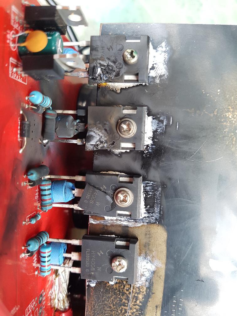 the results after removal Repair did not go smoothly, even though the PCB was not damaged at all due to the whoopsie. After setting up a test with one FET in each leg, I had the chance to capture on video a lovely example showing why nobody should ever hire me as an electronics trouble shooter. first power up attempt After that, I eventually found that all 4 TIP4x transistors were blown and the 20R gate drive current source for one of the high sides. But now all is well and time to see what is causing this inverter to die after a week. This time death occurred when driving a 500W load. I wonder if the toroid is bad in some way, or maybe the choke is no longer adequate... Something must be the cause of it. Time for some homebrew and a bit of a think. wronger than a phone book full of wrong phone numbers |
||||
renewableMark Guru Joined: 09/12/2017 Location: AustraliaPosts: 1678 |
That's a top effort there! Even blow up Marky fella hasn't managed to blow all fets in one go. Only ever blew up half the board, and some of them blew tracks completely off totally destroying the board. This is where Mad would normally chime in and say if you have an 80A breaker on the DC side that damage won't happen. Well yes that's correct, but I regularly pull more than 80A so my unit needs much more than 80A. So that's a BIG puzzle. Why would they all blow? Cheers Caveman Mark Off grid eastern Melb |
||||
| poida Guru Joined: 02/02/2017 Location: AustraliaPosts: 1418 |
Maybe the low side FETS were OK, but I was not going to leave them to possible cause issues once I repair the board. I strongly suspect only the high side FETS all blew. wronger than a phone book full of wrong phone numbers |
||||
| johnmc Senior Member Joined: 21/01/2011 Location: AustraliaPosts: 282 |
Been there down that, nice action shot but most distressing  What is the source of your semi conductors, I now use the same suppler of semi conductors as madness and have had no trouble, touch wood, for many months and my daily use in winter is usually 15 kw per day. Most of my previous light and smoke shows , usually happened with very light loads, cheers john johnmc |
||||
| poida Guru Joined: 02/02/2017 Location: AustraliaPosts: 1418 |
thanks Johnmc for the comments. It's all evidence to be used when looking for clues or a hint which way to jump. It's repaired and running again. I replaced all mosfets, a 20R gate drive current creator, and both TIP 41/2 on the high side. No damage was made to the power PCB. On reassembly I discovered the "47uH" ferrite choke was only about 35uH when I checked it using a pulse tester. OK, I built another choke using one of the Aerosharp iron cores, adding about 20uH which I hooked up in series. With these 2 in series, saturation kicks in at about 50 A or more and that's where I want it. No lower. My loads do not require much more than 50A anyway. RenewableMark uses a ferrite and an iron core choke in his home inverter. I found the PCB type 240V-12V transformer was bringing some trouble. This was a surprise for me. A transformer is a transformer. The bench test inverter (nanoverter control board and Madness power board) uses a simple EI type 240V-9V transformer out of a wall wart. Adjusting the output voltage is simple and easy and accurate. You turn the 2K 30 turn trimpot one turn and the AC volts go up or down 2 volts or so. No matter where you are, the one turn produces the same increment. In the case of the PCB transformer, it was as expected, running it up to about 180V AC, then I turn the trimpot ONE turn and the AC output goes from 195 to 200,210,220, 230V and remains at 230V. what? There is a very unstable situation there. I want 240V so I trim it a 1/2 turn and it goes from 230 to 240,250 then 260V. What is going on here? I used the PCB tranny in the first attempt that lasted 7 days. Once I replaced the PCB tranny for a 204V-10V EI type I was back to the very linear relationship of AC output voltage and trim pot screw turns. I wonder if the AC output was all over the place due to the PCB tranny. Oh, and I found I overlooked fitting the low side 104 snubber capacitors to the power board. Maybe the absence of those let the events build to blow up. And I used a low power 60-15V DC-Dc converter to power the nanoverter. I did NOT expect it to drive the cooling fans, I had an external 12V supply for those, which were controlled by the nanoverter on-board N type FETS quite happily. This low power dc-dc converter makes easily enough to run the nanoverter and power board, maintaining the 15, 12 and 5V supplies accurately. And so we wait and see what we will see now it's running the house again. wronger than a phone book full of wrong phone numbers |
||||
renewableMark Guru Joined: 09/12/2017 Location: AustraliaPosts: 1678 |
Was that the same potted transformer in the red case I dropped off? I use the exact same one and found voltage setting a pain, but it hasn't caused any issues since being set months ago. Cheers Caveman Mark Off grid eastern Melb |
||||
renewableMark Guru Joined: 09/12/2017 Location: AustraliaPosts: 1678 |
Where would 35uh saturate? Cheers Caveman Mark Off grid eastern Melb |
||||
| poida Guru Joined: 02/02/2017 Location: AustraliaPosts: 1418 |
Mark, the 35uH thing saturated about 35A. This was OK-ish to my mind since it spends all the time at 500W with short pulses of 2kW (@ 50V DC) What concerned me the most was the fact the LCR meter showed it was 48uH but the pulser showed it was 35uH. I took a very similar choke out of the standby inverter I built and it was 47uH (LCR) and 45uH from the pulser. What is going on that makes one ferrite choke (same material, just minor differenc in air gap) behave differently to another on the pulse inductance rig. I figured "stuff it" and just made another choke using the large Aerosharp iron core, and stuck it in series to get enough 'Enries. The potted transformer was the one you gave me. And you have problems setting the output voltage too. hmm. No issues using it means I rule out this as a cause. I just checked it with the LCR. at 100Hz, primary is 31.8 H, secondary is 491mH Primary DC resistance is 3.6K, secondary is 33 Ohms Leakage is 2.9H on the primary and 18mH on the secondary. Comparing this to a little EI iron cored plug pack transformer (maybe 20V secondary) everything is 10X bigger with the PCB tranny. I got much much better setting of the AC output once I changed out the Red PCB tranny and put in an EI plug pack with a 9V output. I am not so sure the PCB transformer is the way to go, and I rather prefer 9 or 10V output too. wronger than a phone book full of wrong phone numbers |
||||
renewableMark Guru Joined: 09/12/2017 Location: AustraliaPosts: 1678 |
If you make it go pop again borrow one of my big chokes, they are 120+ Maybe think about connecting the primaries to the heatsinks. I know it should work the other way but it's good to rule things out. Very odd how it blew while running, I have never seen that, every problem I had was on start up. (self induced  ) )Cheers Caveman Mark Off grid eastern Melb |
||||