
|

|
Forum Index : Electronics : building an Inverter from scratch
| Author | Message | ||||
oztules Guru Joined: 26/07/2007 Location: AustraliaPosts: 1686 |
Looks like it will fit then. What inverter do you currently run? .............oztules Village idiot...or... just another hack out of his depth |
||||
Madness Guru Joined: 08/10/2011 Location: AustraliaPosts: 2498 |
I have 2 Trace SW4548E they do a good job but don't have the hardware to make them run as one 9 KW, secondly have not been game to try welding with them, thirdly my metal abrasive saw causes it to shut down on start and they where build last century. So getting old and Trace don't exist anymore. Being able to use the inverter to run everything without fear is my main reason for doing this build. What I will miss though is the ability to charge, so will be building another Torriod the same size to make a battery charger. So my 8 KW Lister generator can charge at full power. Auto start will be easy to do with an Arduino, so if battery volts are down etc the generator will kick into action without any human involvement. There are only 10 types of people in the world: those who understand binary, and those who don't. |
||||
| yahoo2 Guru Joined: 05/04/2011 Location: AustraliaPosts: 1166 |
I will be interested to see how you get on. I have got to about 65% capacity with welder transformers and a soft start mechanism. if you can ramp it up slower than the AVR adjusts you might get it to work. battery charging can be a brutal load on a generator. I'm confused, no wait... maybe I'm not... |
||||
Madness Guru Joined: 08/10/2011 Location: AustraliaPosts: 2498 |
I was thinking of making it have some brains controlling Mosfets to bring on the load gradually then limit amps to a set number till absorb voltage is reached and then limit the voltage. There are only 10 types of people in the world: those who understand binary, and those who don't. |
||||
| yahoo2 Guru Joined: 05/04/2011 Location: AustraliaPosts: 1166 |
I have used something similar at ten times the price. Do they list the transformer that goes with it? My personal experience is that no customer ever looks at it. instantaneous kwh and battery capacity meter fitted in the kitchen, that gets a big tick. although they are handy in a workshop setting 4 in 1 digital meter another option. you are right there are tons of them. I'm confused, no wait... maybe I'm not... |
||||
| yahoo2 Guru Joined: 05/04/2011 Location: AustraliaPosts: 1166 |
OK, if you have trouble there are a few tricks we used with the big victron chargers that might help, I could dig out my old notebooks, not something I need anymore so I have forgotten the details. regular sunshine and cheap panels have ended the reign of the big charger here, I might install a pair of 2 kw PFC units on a really big system at a pinch. I'm confused, no wait... maybe I'm not... |
||||
Madness Guru Joined: 08/10/2011 Location: AustraliaPosts: 2498 |
Here on the Sunshine Coast, we can get weeks of really cloudy wet weather. Micro hydro is a possible option for those big rain events. The battery charger may come sometime later as I can still charge with my Trace Inverters. Not sure how much life I can expect from them, if anyone has any old SW4845E's dead or alive I would be interested if the price is right. While I have been winding I was thinking 2 Torroids together with rewound primary would be a far easier option, with the right number of turns might be all that is needed, or even to be able to switch in or out an extra turn or 2 perhaps Oz has a suggestion here? There are only 10 types of people in the world: those who understand binary, and those who don't. |
||||
| yahoo2 Guru Joined: 05/04/2011 Location: AustraliaPosts: 1166 |
I wondered if you could do 2 low voltage windings. The large diameter wire set to a bulk charge voltage limit, and a separate thinner winding for equalisation duties. I'm confused, no wait... maybe I'm not... |
||||
Madness Guru Joined: 08/10/2011 Location: AustraliaPosts: 2498 |
I am not worried about equalisation or even much absorption while running off of the generator. When I get 2 days of good sun after extended cloudy weather the batteries recover to 100% SOC. There are only 10 types of people in the world: those who understand binary, and those who don't. |
||||
oztules Guru Joined: 26/07/2007 Location: AustraliaPosts: 1686 |
You already have 6kw chargers on your bench... ie 2 x 3kw aerosharps will do fine. Simply rectify the 240vac to dc, and feed in the solar inputs.... it will reverse into the battery bank and run the house at the same time. Use a few of the ballasts from other aero sharps to limit the current to what you want. Too simple, and should do a better job as well. The rectification to the battery is synchronous too. You can also use a capacitor bank to soften the power to the aerosharps if you want to govern the input a lot more.. a 2-4 hundred uf@450vac caps should be more than good. The torroid is an excellent transformer for everything that requires tight control.... battery charging is not one of those things... unless you control it.... simple stuff it is too. I use a small board and 9 fets to control 100 amps from the panels, easy to use on the torroid rectified as well with a few small changes. Torroids do not have much of an output range... if it is 50v then it is 50v +- a few, but past that, it will probably blow big fuses. It needs ballast or fet control or triac control on the input.... pretty scary too if not done right. ...........oztules Village idiot...or... just another hack out of his depth |
||||
| yahoo2 Guru Joined: 05/04/2011 Location: AustraliaPosts: 1166 |
post removed by yahoo reason: talking rubbish!  I'm confused, no wait... maybe I'm not... |
||||
Madness Guru Joined: 08/10/2011 Location: AustraliaPosts: 2498 |
All the Areo Sharps in my possession have been gutted 
The SX460 AVR has a variable resistor on it to adjust voltage, 10% variation. Could varying the input voltage to the Torroid over come the inflexibility of it? Also it has a roll off function that reduces the voltage if the frequency drops, the Lister Engine is most happy running at full load. There is also an option to control the field voltage either manually or with a custom AVR. There are only 10 types of people in the world: those who understand binary, and those who don't. |
||||
oztules Guru Joined: 26/07/2007 Location: AustraliaPosts: 1686 |
Yes Think of the torroid as a rigid device, and you charger needs to be flexible and dynamic in range. You need to accommodate 45v to 62v.... this is not the stuff of a stiff torroid. We want to use reactance to give us a flexible range, as there is no power loss... so yes a resistor would do it, but lossy, reactance via phase vector or inductive reactance will not cost us diesel. So capacitive reactance can be hundreds of uf or so on the input to the torroid, and this will work very well, or the filter chokes from the aerosharps will mostly be keeping the current in check with reactance to the frequency, some resistance, but it will essentially be ballast... perhaps two to three of those 4mh chokes in series might do it nicely for say 40 amps. I think they are 15amp from memory in the 3kw aero's. This will also allow the thing to start without causing a direct short on the genny. If you can vary the AVR automatically, then yes you may squeak it in.. playing will tell. ..........oztules Village idiot...or... just another hack out of his depth |
||||
| Tinker Guru Joined: 07/11/2007 Location: AustraliaPosts: 1904 |
Thanks for that oztules, it makes a lot of sense. Now I'm back home to do some more tinkering on that project. Re doing that little sense PCB should be easy. I assume that after rectifying the 12V secondary you connected it to the same value trim pot? Klaus |
||||
Madness Guru Joined: 08/10/2011 Location: AustraliaPosts: 2498 |
Is there anybody out there with a 3 KW Aero Sharp in one piece that could take some pictures of where all the wires go? Even better would be a service manual for one, would nice to be able to get into the setup as well. After ripping all the ones I have apart to get the transformers out I am now wanting to reassemble a couple to use as chargers as per Oztules suggestion above. Gary There are only 10 types of people in the world: those who understand binary, and those who don't. |
||||
oztules Guru Joined: 26/07/2007 Location: AustraliaPosts: 1686 |
Tinker... yes. Madness.... yes tomorrow maybe. ..........oztules Village idiot...or... just another hack out of his depth |
||||
Madness Guru Joined: 08/10/2011 Location: AustraliaPosts: 2498 |
Thanks OZ, Not urgent, when it is convenient. Parts are trickling in for my build, have power PCB ready for etching, fingers crossed all goes well and top and bottom are aligned. once I have confirmed it okay I will order some to be made from China. Have you tried adding the serial LCD display to the EG8010? There are only 10 types of people in the world: those who understand binary, and those who don't. |
||||
oztules Guru Joined: 26/07/2007 Location: AustraliaPosts: 1686 |
lcd display.... no, it has nothing I cant get directly already except the frequency.... and that never changes anyway. I will try to get a flat card version into a aerosharp 3kw box today or tomorrow, and see how the temp goes. The daily hot water run is a fair test for long period 3kw draws. ( 3hrs). Thats long enough to get some decent figures regarding thermal heating of the unit... it won't have a fan for this test. If I could get to the aerosharp parameters I would be very happy... but not as yet. I need to change the frequency range for over here... +-4hz, but aero is +- .5hz... dammit. Other than that they are very good grid ties indeed. Been running them for years now .. no problems at all. ..........oztules Village idiot...or... just another hack out of his depth |
||||
| Tinker Guru Joined: 07/11/2007 Location: AustraliaPosts: 1904 |
OK, time for an update to this thread I originally started. The electronics for this project have been finished for quite some time and my Aerosharp 3Kw toroid transformers were waiting patiently for me to tackle the rewinding. As soon as had I unwound the mylar film strip hiding the connections I started wishing that I had procrastinated a little longer..... The top winding (250V) was wound 3 in hand with 1.8mm diameter wire, nothing unusual there. Only this time they wound the 'three in hand' literally. Yes, three wires side by side wound on at the same time. Nothing like the 'wind one wire at a time and then connect them in parallel' idea I had faced with my first toroid conversion (tinker's inverter project). So, off it had to come, all three wires were wound onto my shuttle at once. 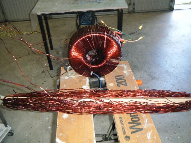
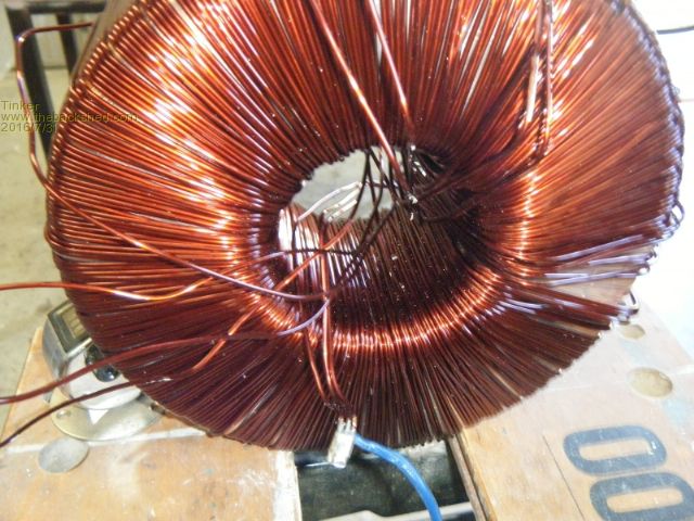
This was about 10 times harder to do than the one wire at a time method. My shuttle was getting very full with all that extra wire. And just to give me more challenges they managed to sneak in the odd riding turn (one wire being trapped under a subsequent turn of the same wire)which is not easy to clear with three sets of wires adding to the confusion in the toroid hole. Luckily they only wound on one layer then joined the wires for the next layer so I had a ready place to apply my side cutters. There was no mylar tape at all wound on between the two layers, perhaps the factory had a tape shortage as I noticed later on the inner, 230V winding had only a non complete mylar tape covering. Anyway, with half of the 250V winding now on my shuttle I had to carefully unwrap it along the floor of my garage and adjoining workshop, some 20m distance in total. The wire was longer than that. Now came the tedious task of separating the 3 wires which, naturally, were by now twisted around each other. Then I straightened each wire so it could be coiled for future re use. I use this idea for wire straightening after first pulling the wire through the funnel like shape of a cartridge gun nozzle to remove the bigger kinks. 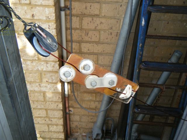
The wire is run through the sheave tied to the door frame. Its end is fastened to the straightener and thus I effectively could straighten wire twice as long as the 20m distance I had. Which was just as well as the rain outside did not encourage walking out the shed door pulling on the wire. Then came a repeat of the above with the other half of the 250V winding. On this toroid the electrostatic shield was in copper foil which pleased me, much easier to re use than that horrible alu foil strip they used on my first toroid conversion. 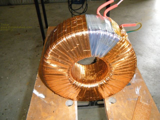
The 230V winding was, thankfully, wound one wire at a time. It was also a 3 in hand winding of 1.8mm diameter wire. 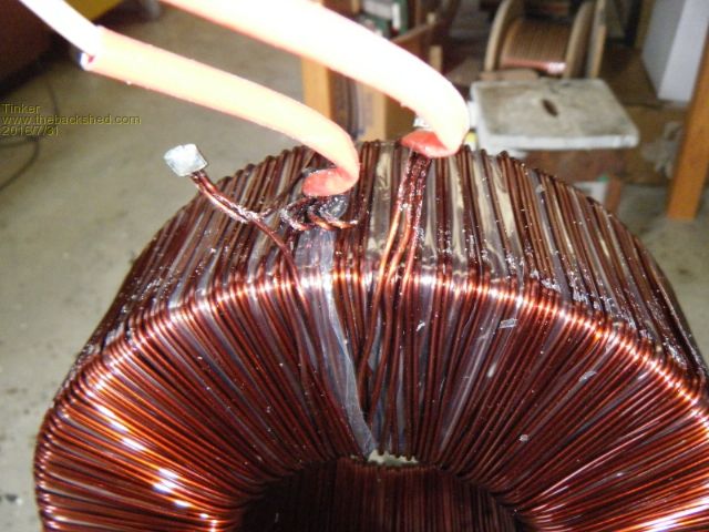
After straightening and coiling all the wire I had 7kg of it and another 7kg to come. A good size core was found under all that wire. 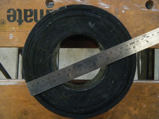
This one, at 203mm OD is bigger than the 190mm OD core I got for my first inverter project. A twin stack core will give me 7420mm sq of core area which calculates to a theoretical ratio of 2.47V/ turn. I will be using the lower ratio of 2.3V/ turn which I got by experimental measurement and use 100 turns for the secondary. Using 4 in hand of the 1.8mm wire should make a very robust winding. I'm not sure yet what to use for the 11 turn primary but definitely not the many many thin wire in parallel idea described elsewhere here. That one is in the too hard drawer in my workshop. Surprisingly, when I compared the labels on my toroids (which were all made on the same day) the toroid windings were quite different from what madness posted on his toroids. All were made by the same manufacturer and mine only made a few days later of the same month and year. 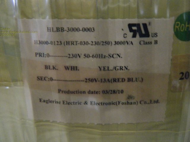
So, anybody starting up an inverter rebuild project, you are in for some unwinding 'fun' if your donor Aerosharp toroid transformer bears the above label. Klaus |
||||
Madness Guru Joined: 08/10/2011 Location: AustraliaPosts: 2498 |
I have unwound some with the same label, with a bit of fiddling I found the last wire to wound on and away I went 1 at a time. Looking at the price of heavy gauge wire I would wind the same as before with 2mm wire on the primary. I have been trying to continue straight on to the choke with it but I may give up and use something else for those 3 turns. There are only 10 types of people in the world: those who understand binary, and those who don't. |
||||