|

|
Forum Index : Windmills : Fisher & Paykel Micro Hydro
| Author | Message | ||||
| VK4AYQ Guru Joined: 02/12/2009 Location: AustraliaPosts: 2539 |
Hi Yahoo2 Good idea but you need the propeller at the bottom of the riser just above water race level to get Max power from additional head. All the best Bob Foolin Around |
||||
| herbnz Senior Member Joined: 18/02/2007 Location: New ZealandPosts: 258 |
These units use the vortex action in the draft tube to create a spinning action So prop at the top Herb |
||||
| Warpspeed Guru Joined: 09/08/2007 Location: AustraliaPosts: 4406 |
How does something happening way down stream of the prop influence the prop ? Cheers, Tony. |
||||
| Hydro John Newbie Joined: 31/10/2011 Location: United StatesPosts: 35 |
Hello Friends, I am totally amazed at the response and comments that have been posted and I thank all of you for your input. Please keep in mind that I am new to all this and am learning as I proceed with my project. I am still awaiting the arrival of my testing equipment, so still cannot do any accurate testing. I am not quite ready to give up on my pelton wheel and am in the process of revising it. Hope to have it up and running in a couple of days. I intend to utilize some of the suggestions I have received and have high expectations of some improvements. Will let you know the results. Thanks John Hydro John |
||||
| yahoo2 Guru Joined: 05/04/2011 Location: AustraliaPosts: 1166 |
John, I wouldn't worry to much, some of the responses are not aimed directly at your project. Fact is, some of the issues you are looking at are common to all generators and we have avoided talking about them because the materials available for wind turbine building make it easier to DIY develop low voltage, low RPM machines. I think there may be quite a few new topics spawned from your hydro project. I for one, would like to explore generators locked in phase and also high voltage transmission a bit more. warpspeed and bob, scavenging the water away at a faster rate creates an area of low pressure behind the blades which the water above the blade rushes to fill, almost like a wind turbine. The guide vanes are what get it up and humming. Herb is spot on, its a giant plughole! 
the pressure difference is limited by the point of bad cavitation on the blade surfaces.A 3 metre head is about the limit. yahoo I'm confused, no wait... maybe I'm not... |
||||
| Warpspeed Guru Joined: 09/08/2007 Location: AustraliaPosts: 4406 |
Generators stay locked in phase whenever they are electrically connected to another generating system. Getting them exactly synchronized before you can safely close the circuit breaker and bring a generator "on line" is not all that simple, which is why I urge against doing it that way. Dc connection is far more benign. http://en.wikipedia.org/wiki/Alternator_synchronization And here is a link that explains a very important principle "torque = amps" That is a very profound and very valid concept to understanding rotating three phase synchronous machines when connected together or to a "grid". http://www.control.com/thread/1272536595 Cheers, Tony. |
||||
| yahoo2 Guru Joined: 05/04/2011 Location: AustraliaPosts: 1166 |
If you are interested in water turbines of all shapes and sizes this guys gear is worth looking at. I see his stuff everywhere. Mr. Tomaz Razpet TINCK INZENIRING Cerkno Slovenia 
he does Francis, Kaplan, Denki, crossflow and Pelton from the size of your hand up to 3 MW. yahoo I'm confused, no wait... maybe I'm not... |
||||
| Don B Senior Member Joined: 27/09/2008 Location: AustraliaPosts: 190 |
Hi John, On the topic of the suitability of different turbine types for your application, there is a measure called turbine specific speed, which relates the desired shaft speed, power output, and available head. Wikipedia and other internet references give a reasonable explanation of how it is calculated. This measure suggests the most suitable turbine type for a given application. Impulse turbines such as the Pelton operate with low specific speeds (around 4), while propellor type turbines, such as the Kaplan operate at 100 and above. Note though that this measure only indirectly allows for the amount of flow available, in that the P or power element of the calculation would not be sustainable if you sought to extract more power than your water supply flow could consistently give. While the available head is low for an impulse turbine in your application, so is the available flow on a long term basis, so an impulse type turbine is probably the best choice. You just have to accept that you can not get more electric power from the set up than the available hydraulic power. Incidentally, with regard to your Pelton wheel, I realize now that it is intended to work only with a single nozzle, with the flow being split (and reversed) by the bucket pair, and discharged from the sides of the buckets. If you are re-working your Pelton wheel, it would be worth paying attention to the area where the buckets touch and the split occurs, as this needs to happen as cleanly as possible. A dual nozzle, of the type that I previously suggested, would not be of any value, and this is apparently consistent with your test results. Accurate aiming of the single nozzle is, however, quite critical, again as you have found. Despite all of the above, the suggestion by Warpspeed of trying a turbocharger as a turbine might be an interesting experiment, if you ever get the opportunity. Regards Don B |
||||
| Warpspeed Guru Joined: 09/08/2007 Location: AustraliaPosts: 4406 |
Whenever I see a picture of a Francis water turbine, it always looks EXACTLY the same as a turbocharger. 
the blade shapes of the turbine (on the RHS) are absolutely identical.  Cheers, Tony. |
||||
| Gizmo Admin Group Joined: 05/06/2004 Location: AustraliaPosts: 5078 |
A turbo could be made to work, but I wonder if the time in modifications would outweigh the convenience of a nice looking impeller and housing. Exhaust housings are usually cast iron, the impeller an allow of steel, and they would rust. And you would need to fit bearings, most turbo's use a oil fed bush. Also, turbo's are designed for compressible gasses, but we are using non-compressible liquids, so maybe the impeller shape is not the best for a hydro application. But if you have a old turbo thats no longer servicable, it might be worth a try. Also worth having a look at is the hydro power plant at Paronella Park. http://www.thebackshed.com/Windmill/articles/ParonellaParkHy dro.asp. Its a similar design to the one Yahoo posted a picture about, only mounted horizontally instead of vertically. Unfortunately I dont have a picture of the impeller, but you can see the guide fins on this page http://www.paronellapark.com.au/hydrows/progress4.html Glenn The best time to plant a tree was twenty years ago, the second best time is right now. JAQ |
||||
| Hydro John Newbie Joined: 31/10/2011 Location: United StatesPosts: 35 |
Hello Friend, I didn't get to do any work on the project today, but I have given some thought to the different types of systems that have been mentioned. I hope to get to do some work on my pelton spoons tomorrow and I think that the suggestions that have been made will be easy to implement and hopefully see an improvement. After close examination of the spoons as currently built, I can see where the reflected spray is probably hitting the spoon directly behind and causing some interference. I like to use materials that are readily at hand and especially used items, and so hesitate to purchase prebuilt items like the pelton wheels from commercial sources. I have used several items from the old washing machine, even the lid. I may have to settle for a lesser quality and performance, but to me the trade off will be worth it. I do realize that I may not be able to built everything from salvaged items but I want to do all I can. I am still awaiting the arrival of my testing equipment. Will keep you posted. John Hydro John |
||||
| yahoo2 Guru Joined: 05/04/2011 Location: AustraliaPosts: 1166 |
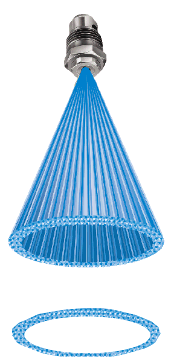
There is always a tradeoff with homemade stuff. I look at your wheel and think, wow, I couldn't afford to pay for all those PVC elbows at retail prices. PVC is quite brittle, you may get a lot of wear at the point the water hits the spoons centre ridge. If the rig proves it self and works well then long term the commercial replaceable poly spoon may end up a cheaper option. I was wondering, would there be any advantage if a swirl plate was fitted inside/behind the nozzle? The water could be focused into a small hollow cone instead of a point making it easier for the divider in the spoon pair to split it. this technique is used a lot in fire fighting equipment and agricultural sprayers for certain applications.  
yahoo I'm confused, no wait... maybe I'm not... |
||||
| Warpspeed Guru Joined: 09/08/2007 Location: AustraliaPosts: 4406 |
Glen, turbine wheels and shafts are made of austinitic stainless steel, and simply will never rust, corrode, or erode. Turbine housings about forty to fifty years ago were cast iron, and rust would certainly be an issue. But modern turbos since about the 70's all now use high nickel content iron which is also completely rust free. You never see a rusty turbine housing these days. For trial purposes a bush type bearing will work fine, a later ball bearing turbo could be packed with water reesistant boat trailer wheel bearing grease, and fitted with a grease nipple. And the very complex compound curved blade profiles are absolutely identical between a water turbine and a turbocharger turbine. The flow dynanmics of a free vortex are identical, and it is a very efficient way to extract power. Although small, every single blade contributes to torque through 360 degrees, and they should be even more efficient with much denser water than with gas. And a wide range of nozzle area sizes are available. I just don't have a suitable water flow available here in suburban Melbourne to try the idea out. Cheers, Tony. |
||||
| BobMann Senior Member Joined: 30/06/2011 Location: United StatesPosts: 134 |
I was going to bring this up I rebuild a lot of VW turbos.The bushing and the all most no seal design would be the thing to fix just come up with the right sealed bearing setup. If you were slick you could use both sides ex/compressor and spin of the end shaft to a PMA. Bob Mann |
||||
| Hydro John Newbie Joined: 31/10/2011 Location: United StatesPosts: 35 |
[quote=yahoo2]There is always a tradeoff with homemade stuff. I look at your wheel and think,wow, I couldn't afford to pay for all those PVC elbows at retail prices. PVC is quite brittle, you may get a lot of wear at the point the water hits the spoons centre ridge. If the rig proves it self and works well then long term the commercial replaceable poly spoon may end up a cheaper option.[/quote]Yes the elbows are expensive, about $0.60 each, with 2 for each spoon. That makes 40 elbows and $24.00, not to mention the labor involved. But I've had fun doing it and I have spent a lot more and got a whole lot less. Like you said, if it proves to be worth a hoot, I'll probably go the commercial route, but right now, I don't have a clue as to what size to get. Hopefully some more testing will give some idea. About the swirl plate behind the nozzle, may be worth looking into after I have a go at what I have now. Thanks for the suggestions. John Hydro John |
||||
| herbnz Senior Member Joined: 18/02/2007 Location: New ZealandPosts: 258 |
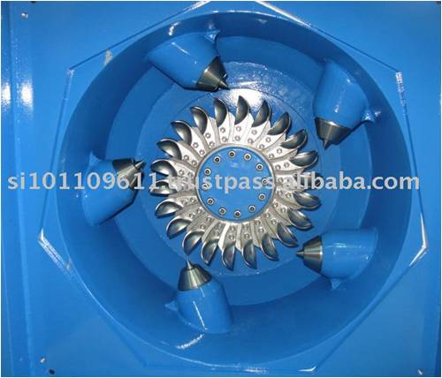
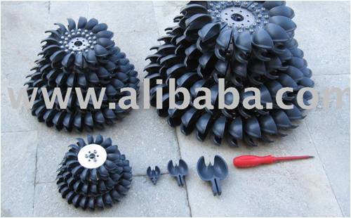
Cups should be 5 times the size of the largest nozzele used. I have cups here that are about 30mm but i am sure there is a supplier in the States. Cost here is about $5 (nz) However the efficiencies you Have been getting here seem justify you proceeding with your approach. I have build a lot hydro's been involved with a lot more and with micro hydro's the efficiencys range from 30% to 60 %. when the water hits the wheel it ideally should deflect 180 degrees this is immpossible pelton designs for 165 . Water hiting a flat plate will in theory max eff possible is 50% so bearing losses etc are on top of this. Herb |
||||
| Hydro John Newbie Joined: 31/10/2011 Location: United StatesPosts: 35 |
Hello Friends, [quote=herbnz]However the efficiencies you Have been getting here seem justify you proceeding with your approach. I have build a lot hydro's been involved with a lot more and with micro hydro's the efficiencys range from 30% to 60 %. [/quote] Thanks for the encouraging words. I got my revised wheel up and running today, but no time to do much testing (still waiting on testing equipment), but looks promising. I am confident that I can get close to the 60% efficiency range. Hope to do some more testing tomorrow. Thanks John Hydro John |
||||
| Greenbelt Guru Joined: 11/01/2009 Location: United StatesPosts: 566 |
herbnz : herbnz wrote: when the water hits the wheel it ideally should deflect 180 degrees this is immpossible pelton designs for 165 . Water hiting a flat plate will in theory max eff possible is 50% so bearing losses etc are on top of this. Herb Hi I appreciate that you have posted info that is nuts and bolts possibility rather than theory. I am Guilty of throwing out the 100% Numbers at times, Maybe the Theory is a part of better engineering (Try Harder to measure up). In a nutshell A good Post. ----------Cheers, Roe Time has proven that I am blind to the Obvious, some of the above may be True? |
||||
| Hydro John Newbie Joined: 31/10/2011 Location: United StatesPosts: 35 |
Hello Friends, I finally received my Clamp on Multimeter a few days after Christmas (UNI-T UT204/TRUE RMS). It came with a manual written in Chinese and I do not read Chinese. I was able to find one written in English on the net, but it does not explain how to use the functions very well. I am not well educated in the use of amp meters and I am hoping someone can help. My biggest problem now is, when I turn the meter to the amp function, it does not read 0 but it has a variable reading. It has a Rel delta function but I'm not sure if I should press this button before I take a reading or not. I have taken amp readings with and without pressing the Rel delta button and I get different results. Can someone steer me in the correct direction? My new and revised pelton wheel seems to be holding up well and is giving better results. I have reworked my outlet works to accommodate an additional unit and have moved it away from the creek, which is prone to flood during periods of heavy rain. This also allowed me to cover the exposed piping with sawdust to protect from freezing. So far no frozen pipes. My little stream has been giving much more flow than the 50 GPM I originally measured, which has encouraged me to begin construction of a small dam to provide a total head of about 28'-30'. This is probably going to take most of the summer. Right now I'm in the process of clearing the area of trees. By the way, in a battle between a 15" Eastern Hemlock and a 4" PVC penstock, the Hemlock will win every time. My system is down now because of a busted penstock. Will keep you posted. John Hydro John |
||||
| Warpspeed Guru Joined: 09/08/2007 Location: AustraliaPosts: 4406 |
John, I am not familiar with that particular meter, but it sounds as though it uses a magnetic Hall effect device for current sensing. The difficulty with using a Hall device is that the sensitive zero point is going to be influenced by any residual magnetism, including from the Earth's magnetic field. All of these Hall effect meters have some means for correcting for a shifting zero zero before taking a current reading. Often a "zero" potentiometer on older instruments, but more likely a software correcting zero on something more recent. So the procedure will be, close the jaws, zero the reading, then clamp the jaws around the wire you wish to measure. It sounds very much like the "rel delta" button is what you press to zero the instrument before clamping the jaws around the wire to take a reading. Cheers, Tony. |
||||