|

|
Forum Index : Electronics : Micro controller driven Warpverter
| Author | Message | ||||
mackoffgrid Guru Joined: 13/03/2017 Location: AustraliaPosts: 460 |
Totally agree Poida. I don't believe the inverter micro should be overloaded with too much house-keeping stuff. Vdc control and On-Off will do me  I have an interest in not so much mains syncing but with possibly paralleling two inverters together or even 3 phase. I may fit the fan control loop in, maybe. From Tony's and my experience the 74 series stuff drive the HPCL3120 optos fine but obviously a driver will do very well. If the PCB gets too big, I'll jettison some of what I believe is extraneous. I'll just make sure it's compatible with Tony's gear so he can test it, or if there are problems we can go back to tony's clock (eprom) board. Cheers Andrew |
||||
mackoffgrid Guru Joined: 13/03/2017 Location: AustraliaPosts: 460 |
Yes, the blue Pill STMs are a pain in that you have to load a USB boot loader. For those interested in STM32 BluePills: I'd recommend looking at this company (though I haven't tried them myself, yet but I will) RobotDyn's BluePill (although its black) You can order the the BluePill from them with the USB bootloader installed - cost 50c more. For referral purposes read through STM32Duino topic on RobotDyns BluePill Cheers Andrew |
||||
| Warpspeed Guru Joined: 09/08/2007 Location: AustraliaPosts: 4406 |
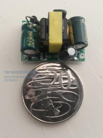
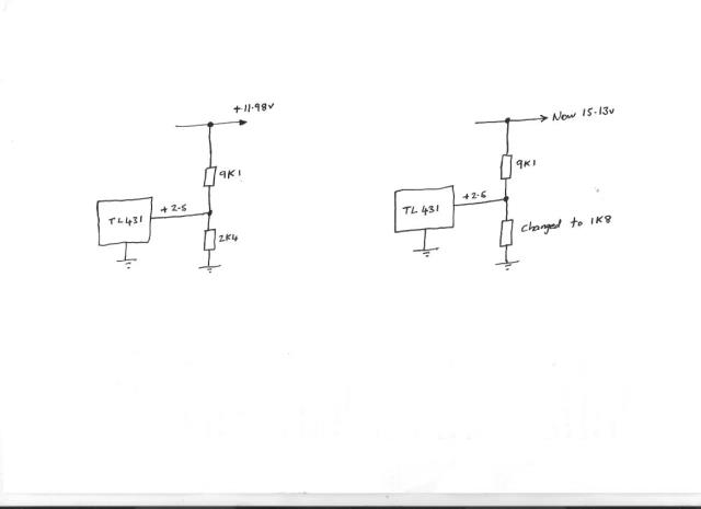
These small boards are the "guts" out of standard world supply wall plug packs, and available from e-bay for about a buck fifty each. Now there has arisen a slight problem. A year or so ago these were available in all the standard dc plug pack voltages, 3.3v, 5v, 9v, 12v, 15v, 18v and 24v. For some reason the 15v units have become impossible to source. I have no idea why. Now the HCPL3120 has an internal undervoltage lockout that needs to reach 11.5v nominal. Using the 12v supplies as is, might be a bit dodgy, 15v supply is preferred anyway for mosfet and IGBT gates. I ran out of the original 15v supplies, so what I have found to be a good solution is to modify 12v supplies to provide 15 volts by changing one of the feedback resistors from 2K4 to 1K8. This works fine, because the supplies are very lightly loaded. A 12v 450mA rated supply only needs to provide gate drive power which is negligible at 50 Hz ! Plenty of suppliers from both Ali and e-bay, These are the type of thing: https://www.ebay.com.au/itm/New-AC-DC-Power-Supply-Buck-Converter-Step-Down-Module-5V-12V-3-3V-9V-24V-500mA/262807265342 ?_trkparms=aid%3D111001%26algo%3DREC.SEED%26ao%3D1%26asc%3D56117%26meid%3Dbdb333065cd9411494f3fafef41c5357%26pid%3D10067 5%26rk%3D2%26rkt%3D15%26sd%3D282701664304%26itm%3D262807265342&_trksid=p2481888.c100675.m4236&_trkparms=pageci%3A8d400b0 3-568e-11e9-9ee0-74dbd180e037%7Cparentrq%3Ae683ba801690a887dd0fc016ffff6dc7%7Ciid%3A1 Cheers, Tony. |
||||
| poida Guru Joined: 02/02/2017 Location: AustraliaPosts: 1419 |
i just got one of these to see if they run at 45V 15V items are offered there. The images seem to me to be of the same device. Maybe. wronger than a phone book full of wrong phone numbers |
||||
| Tinker Guru Joined: 07/11/2007 Location: AustraliaPosts: 1904 |
Very interesting, I did not know about that half hole area business. One learns something new every day on this forum  . Thank you for that info. . Thank you for that info.Now, after 3 layers the hole has shrunk to <70mm (~68mm). Two more layers + shield to go on. I do use minimal between layer insulation, just half overlapped mylar tape. Anything less is a waste of effort. I do flatten the wires in the hole by ramming in a PVC pipe (slotted for the correct diameter) and dare say that method is tighter than Marks balloon ever could be. Now I have to go back in the messages to see where Mark got such a quite different number of turns from. As my secondary is not yet complete I can do less turns if there is an error in my calculations: 6175mmsq core area; 1T; 50Hz; 225V = 169 turns?? Klaus |
||||
renewableMark Guru Joined: 09/12/2017 Location: AustraliaPosts: 1678 |
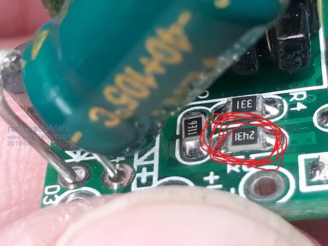
Poida, you'll find that one has a bigger footprint, no big deal unless you wanted it for Warps driver boards. The little ones are this big  I asked these people if they can do a 15v version. Apart from that is it R6 you change Warp? Cheers Caveman Mark Off grid eastern Melb |
||||
renewableMark Guru Joined: 09/12/2017 Location: AustraliaPosts: 1678 |
Tinker I am using the 2kw core for No2 toroid the 75v one. I have a 6kw core for the No1 225v one. Cheers Caveman Mark Off grid eastern Melb |
||||
| Tinker Guru Joined: 07/11/2007 Location: AustraliaPosts: 1904 |
Mark, if I were in your shoes I would hold off with any PCB making at this stage. It appears that having the PCB means for some the whole project is in hand. Maybe so with some small device but definitely not with the warpinverter. This project is a *lot* more involved in complexity and parts count than what those that have successfully built an ozinverter might realise. Do by all means study Tony's schematics very carefully, it took me a while to get my head around how it all connects together. And I failed there at the workings of that control board  but then I have the same problem with Poida's code but then I have the same problem with Poida's code  . .My suggestion for any prospective warpinverter builders is to wind that big transformer first! If, after that there is still any enthusiasm left to proceed further with that project, start ordering the parts for it. Leave the PCB's for last, if you are rolling your own you need the parts anyway first to make them fit. But, above you see Andrew's very nice version PCB's and in a while you'll see mine posted here, which have thew heat sink differently arranged. Andrew & myself have realised that 2oz PCB's are expensive, the bigger they are the more so. That is why there will be 4 identical 2oz power PCB's on my design, one has to order a minimum of 5 anyway  . .I could never understand why oztules & mad crammed everything on one large PCB which could have been easily be done with 2 identical, cheaper, boards. Ditto the driver boards, they will be identical and well under the cheap 100x100 size. BTW, there will be a total 32 x HY4008's on my warpinverter, the maximum I can easy accommodate on a full length aero heat sink. Arranged 4+4, 4+4, 2+2, 2+2, 1+1, 1+1, 1+1, 1+1. Klaus |
||||
| Warpspeed Guru Joined: 09/08/2007 Location: AustraliaPosts: 4406 |
Cannot say for sure Mark. These little boards fit into standard plastic housings so they are the same outside physical size guaranteed. The pcb pads for input and output are "usually" in the exact same place but not always. But there appear to be Multiple Chinese manufacturers making these things. Some have component designators, and some do not. And those that do may not be the exact same, so beware. The circuit component values are all pretty much standard, and there is a voltage divider connected directly across the dc output pins which consists of a 9K1 and 2K4 on the 12v devices. If the 2K4 is replaced with a 1K8 the output voltage increases to typically 15.1v. Altronics have the 1K8 surface mount resistors in packs of five.  Cheers, Tony. |
||||
| Warpspeed Guru Joined: 09/08/2007 Location: AustraliaPosts: 4406 |
I am wondering why you need five layers of 1.8mm diameter wire ? That is going to be five times about 2.54mm squared. Five times 10 amps ! Do you need a 50 amp secondary ? Stop at three layers for a nice thirty amp rated secondary similar to Mark. Fit the screen to that and have perhaps a 65mm hole which allows a much better primary/secondary copper ratio. Cheers, Tony. |
||||
renewableMark Guru Joined: 09/12/2017 Location: AustraliaPosts: 1678 |
Don't underestimate the power of tenacity Klaus. Actually the nanoverter control card is way more complex than the Oz card, if you have problems with your rendition of it, just use the gerbers supplied and the code, it all works perfectly, that is running my house as I type this. T1 6kw 225v is done T2 2kw 75v on it's way T3&4 piss easy. Cheers Caveman Mark Off grid eastern Melb |
||||
| Tinker Guru Joined: 07/11/2007 Location: AustraliaPosts: 1904 |
Yes Andrew, another version is on the way. Always good to have an alternative arrangement  . .It'll be a little while, still waiting for parts to complete the drive board design. Klaus |
||||
| Tinker Guru Joined: 07/11/2007 Location: AustraliaPosts: 1904 |
OK, 169 turns, three in hand of 1.8mm wire required. Only 127 turns fit on first layer. Only 125 turns fit on second layer. Only 119 turns fit on third layer. On fourth layer, 42 turns missing from first layer + 44 turns missing from second layer added (interleaved wound), thus completing hand #1 & 2. Still missing are 50 turns to complete third layer, these are wound evenly spaced on layer five as layer 4 is almost full. Winding it any other way would result in the ends spread all around the toroid circumference. Does that explain it? The 50mm was a worst case estimate, I do hope its closer to 60mm. Mark, I was unaware of your monster size #1 transformer. Sorry about the confusion. You must be a very fast winder, I can only manage one layer a day. Klaus |
||||
renewableMark Guru Joined: 09/12/2017 Location: AustraliaPosts: 1678 |
 Well surprisingly I had very quick replies from the sellers I asked about making 15v versions of the isolated supplies. Unfortunately they were all negative replies. So buying 12v versions and replacing the resistors looks like the only option. Cheers Caveman Mark Off grid eastern Melb |
||||
| wiseguy Guru Joined: 21/06/2018 Location: AustraliaPosts: 1156 |
These guys have 15V units & look to be available from AliExpress. Mount vertically and may be useful to save some board realestate ? Here They are $2 a piece for 15V or 95c for 12V - no guarantees they will start at 30 but Ive ordered 1 x 15V & 2 x 12V to play with - trouble is it takes ~3 weeks + to get them landed. If at first you dont succeed, I suggest you avoid sky diving.... Cheers Mike |
||||
renewableMark Guru Joined: 09/12/2017 Location: AustraliaPosts: 1678 |
So Poida, I was having a think about how you want to drive the fets. You probably are not going to be plug swappable with the warp unit. IE you are not going to have 8 individual half bridge connections, correct? Cheers Caveman Mark Off grid eastern Melb |
||||
| poida Guru Joined: 02/02/2017 Location: AustraliaPosts: 1419 |
The add-on board I want to do, compatible with the nanoverter, could produce outputs compatible with the Warp bridge drivers. I need to have a think out what is needed and what I can be bothered to build. We both might be best positioned if we base your house Warpverter and my test Warpverter on the same full bridge driver boards. You source the signalling from the Warp control board. I source it from the add-on board, running a nano. wronger than a phone book full of wrong phone numbers |
||||
renewableMark Guru Joined: 09/12/2017 Location: AustraliaPosts: 1678 |
OK so did you mean to run a full bridge board like Mack had? My plan of using the already Warp designed 8 half bridges is going to save some design work, but a bit of construction and parts req'd. That way the Warp control board can be used and the modified nanoverter control board can be used if the nano has the 8 half bridge outputs. But, is that how you would design the nano output if you started with a blank sheet? (without a optional desire to use it with the Warp hardware) Cheers Caveman Mark Off grid eastern Melb |
||||
renewableMark Guru Joined: 09/12/2017 Location: AustraliaPosts: 1678 |
Finished the second winding on the 75v trans. 2kw core 104 turns 1.6 2mm2. So I did the same test to check the torroid as done with the 6kw core, but got different results. I assume it's because it has a smaller core and fewer windings. I had both starts of the windings 1&2 connected together with the active via a 100w incandescent globe. Neutral was connected to the loose end of the 1st winding. 114v across there, bulb lit brightly. 114v across connected starts of 1&2 and loose end of No2 winding, bulb lit the same. 0.06v between loose ends. When I close the switch to bypass the bulb (shorting it) the breaker trips. Cheers Caveman Mark Off grid eastern Melb |
||||
| wiseguy Guru Joined: 21/06/2018 Location: AustraliaPosts: 1156 |
Maybe Im reading this wrong but it sounds like you are trying to feed too much voltage into your 75V winding ? Your Variac output feeding the lamp /transformer should be set to ~ 75V? I dont think the transformer has an issue otherwise. If at first you dont succeed, I suggest you avoid sky diving.... Cheers Mike |
||||