
|

|
Forum Index : Electronics : Warpspeed’s low frequency stepped sine
| Author | Message | ||||
| Warpspeed Guru Joined: 09/08/2007 Location: AustraliaPosts: 4406 |
Yes, star connection of the three individual inverter outputs will be much more useful because we need to be able to run with both 230v and 408v mixed loads. Cheers, Tony. |
||||
renewableMark Guru Joined: 09/12/2017 Location: AustraliaPosts: 1678 |
Just going over all the parts that came in. Is this crystal correct it only has 4 pins, but the holes on the board look like the others don't go anywhere anyaway. 3.2768mhz dip14 but it only has 4 pins 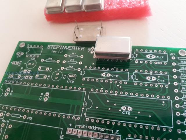 Cheers Caveman Mark Off grid eastern Melb |
||||
| Warpspeed Guru Joined: 09/08/2007 Location: AustraliaPosts: 4406 |
Yes Mark, that is all correct. It uses the 14 pin package size so ten of the middle holes are not used. Make sure it goes in the right way around ! With the writing on the can the correct way up, pin one is the bottom left hand corner. Pin one sometimes has a dot, and the corner of the metal can next to pin one will be "different" to the other three corners. If you are still not quite sure, pin 7 (of the 14 pin footprint)lower right hand pin is connected direct onto the metal can. Cheers, Tony. |
||||
renewableMark Guru Joined: 09/12/2017 Location: AustraliaPosts: 1678 |
Thanks Tony, they were hard to find actually. With the poly caps on the driver boards do they go in position d1,d2? Cheers Caveman Mark Off grid eastern Melb |
||||
| Warpspeed Guru Joined: 09/08/2007 Location: AustraliaPosts: 4406 |
Polyester capacitors C2 and C5 are both 100nF, and C4 is 47nF. Cheers, Tony. |
||||
renewableMark Guru Joined: 09/12/2017 Location: AustraliaPosts: 1678 |
The ones on the little boards for dead time adj I meant. Also it doesn't matter if they are 100v either does it? like this Cheers Caveman Mark Off grid eastern Melb |
||||
| Warpspeed Guru Joined: 09/08/2007 Location: AustraliaPosts: 4406 |
They will be fine Mark. Cheers, Tony. |
||||
| Tinker Guru Joined: 07/11/2007 Location: AustraliaPosts: 1904 |
Mark, it looks like that crystal oscillator is the wrong way round in your picture. I had the same problem finding pin 1. The 'collar' of the metal can has 3 rounded corners and one square corner which is pin 1. The little covered 'window' is on the left then when you look at the board as in your picture. You have 5 crystals there? I guess you do not trust them  . Now I know where I can get another should I need one . Now I know where I can get another should I need one  . .Klaus |
||||
renewableMark Guru Joined: 09/12/2017 Location: AustraliaPosts: 1678 |
Yeah bottom left has a square corner. 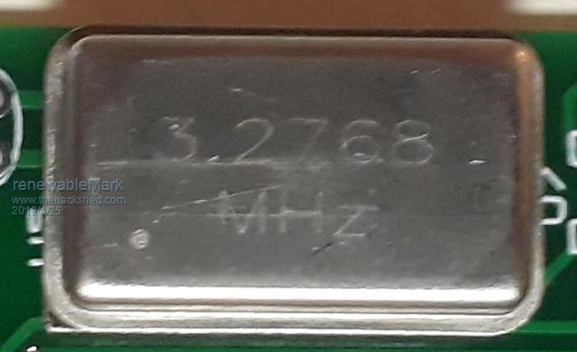 Looked all over for them, finally found them on ebay in a 5 unit deal here Cheers Caveman Mark Off grid eastern Melb |
||||
| Tinker Guru Joined: 07/11/2007 Location: AustraliaPosts: 1904 |
That was a lot cheaper than the single unit I got from More-Suns Electronics Co. which was $US 15.07. Mine, however, has a much better accuracy, 0.1ppm against your 50ppm. I had to search a lot too to find that one, never found anything on ebay like those you found. I fitted mine on a IC socket, perhaps a good idea for yours too as you then can select which one gives the closest frequency to 50Hz if you have something to measure that. Your oscillators don't seem to have that little 'window' on the top, I think there is a trimming adjustment behind it. In case you are still searching, the little caps that go inside the IC sockets are available from RS in a 25 piece pack. Most other caps are too tall to fit under the IC's. Klaus |
||||
| Warpspeed Guru Joined: 09/08/2007 Location: AustraliaPosts: 4406 |
These modules can be a bit of a pain to get, but I managed to score ten from e-bay fairly cheaply a very long time ago. Its worth it though IMHO, they start up and run very reliably, and have a very nice square wave output, and the frequency is also much more accurate than making your own crystal oscillator from a bunch of discrete parts. Quite a few smart hi tech household appliances use the mains frequency to tell the time, its not just clocks. That is useful because the grid is long term time corrected, but an off grid inverter will always have a steadily accumulating error. A typical low cost standard grade of oscillator module might be 50ppm which is about +/- five seconds per day. The higher grade oscillators are temperature controlled (TCXO) and the crystal has a heater, and these can be 5ppm or better accuracy. (half a second per day). Its probably gross overkill, but I already had the modules so decided to use one of them. Cheers, Tony. |
||||
| poida Guru Joined: 02/02/2017 Location: AustraliaPosts: 1419 |
As an aid to visualising the stepped sine shape, I made a small demo program. It runs under Processing. Just load it and run, use the up/down keys or drag the black rectangle with the mouse to change the magnitude of the sinewave. ( get processing from https://processing.org/download/) Maybe this will help some here to understand how subtle the changes to the times when each of the 4 inverters switch on high or low or short, when maintaining as close a match to the required sinewave shape and other aspects of the approximation. 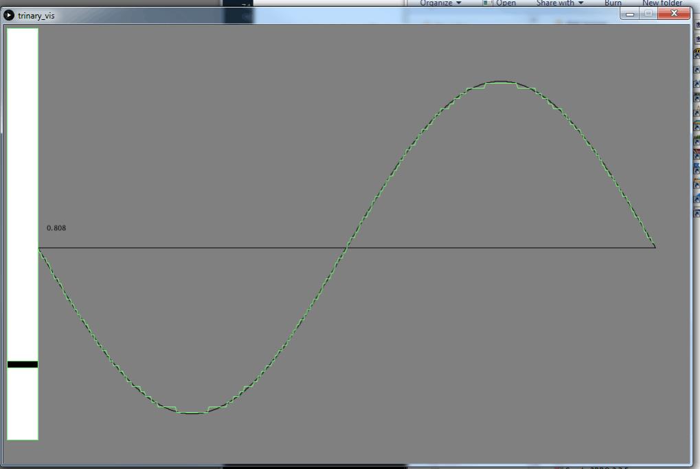 The uploaded image is distorted for some reason. I tried 3 times, 1x png, 2x gif to get a decent representation but no luck. 2019-04-26_120826_trivis.zip wronger than a phone book full of wrong phone numbers |
||||
renewableMark Guru Joined: 09/12/2017 Location: AustraliaPosts: 1678 |
Interesting, my wife's clock has gone out of wack since running the nano, I'll try a different nano and see if that fixes it. Good tip Klaus fitting the crystal in a socket, I didn't think of doing that. Cheers Caveman Mark Off grid eastern Melb |
||||
| Mulver Senior Member Joined: 27/02/2017 Location: AustraliaPosts: 160 |
You could use the sync function of the code to the mains frequency! Edit Ooops!  just realised this was mentioned in Tinkers thread. just realised this was mentioned in Tinkers thread. |
||||
renewableMark Guru Joined: 09/12/2017 Location: AustraliaPosts: 1678 |
Well, we shouldn't really be sync'ing to mains, the nano design said not to do that, and it was only designed to sync with other devices. Anyway once all the reliability is sorted out the mains will be disconnected altogether. ATM it's just there as a backup, still $100 a 1/4 down the toilet. Today we ran reverse cycle on heating, we had 100% cloud cover, but had enough panels to power it. I just programmed another nano and put that in the inverter to see if that one is any better. I know the crystal in the Mad board was pretty accurate as it never needed altering. Just a bit hit and miss I guess. Cheers Caveman Mark Off grid eastern Melb |
||||
| poida Guru Joined: 02/02/2017 Location: AustraliaPosts: 1419 |
What do you mean? wronger than a phone book full of wrong phone numbers |
||||
renewableMark Guru Joined: 09/12/2017 Location: AustraliaPosts: 1678 |
I thought you said not to do that. Cheers Caveman Mark Off grid eastern Melb |
||||
| Mulver Senior Member Joined: 27/02/2017 Location: AustraliaPosts: 160 |
I believe that syncing the "frequency" of the off grid inverter to mains frequency is not an issue. The issue lies in any connection of the inverter AC output and mains power, this would be very bad. |
||||
| Warpspeed Guru Joined: 09/08/2007 Location: AustraliaPosts: 4406 |
I can see two potential advantages (for some applications) where frequency locking to the grid might be an advantage. The first is long term corrected time keeping. And the second is where night time power is drawn from a grid powered rectifier, when there is no battery. If the inverter is mains frequency locked, the ripple voltage from the rectifier will coincide with the pulsing load demand of the inverter. That should solve any problems caused by a slow cyclic beat frequency developing which might cause the dc voltage to the inverter to cyclically rise and fall. That has not been a problem for me, because I am fortunate enough to have three phases available for rectification. But for most people that only have single phase grid power available, a single phase rectifier is going to have a far higher ripple content that will be more difficult to filter out completely. Cheers, Tony. |
||||
renewableMark Guru Joined: 09/12/2017 Location: AustraliaPosts: 1678 |
It's been School holidays so we took the little demon on a couple of caravan trips. Back onto it now. I spoke to Warp about the torroids and decided to use the ones I have here since they are already stripped, and may as well use what I have on hand. So No3 will use a 2kw core 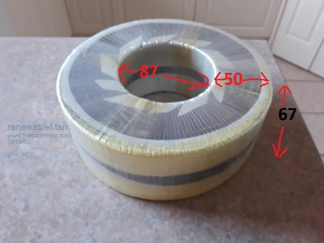 No4 will use a 1500w core ID 94mm ID to OD 46mm Height 47mm 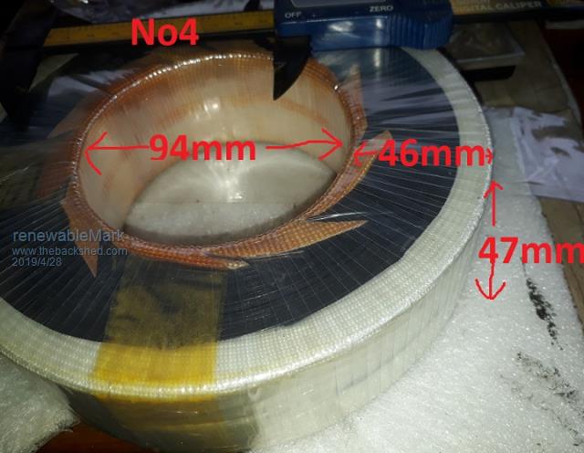 All the bits for the warp control card are in and have ordered the 8 driver boards and their components. I should start a different thread for that build, but the torroids will be a common use for either build. Poida how are you going with the torroids? Cheers Caveman Mark Off grid eastern Melb |
||||