
|

|
Forum Index : Windmills : My unorthodox Build
| Author | Message | ||||
Bryan1 Guru Joined: 22/02/2006 Location: AustraliaPosts: 1344 |
http://www.alton-moore.net/wind_calculations.html Been using this wind blade calculator for years and it is pretty accurate |
||||
| BarkyJ Senior Member Joined: 26/04/2018 Location: New ZealandPosts: 114 |
Hi Bryan1, This was one of the first ones I had seen actually, but it says the same sort of thing. At the root, its like 400mm wide. That is massive. 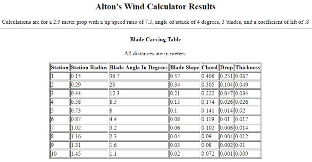 Just doesn't make a lot of sense to me right now... |
||||
Madness Guru Joined: 08/10/2011 Location: AustraliaPosts: 2498 |
You might have missed this part. Please note that near the hub you will usually be limited as to the blade's angle/slope, chord, and thickness by the size of the material. Usually it will suffice to use the largest result which fits in the material you are working with, or just carve the flat side of the prop from one corner to the other of the (rectangular) material. The outer part of the prop is the most important anyway. There are only 10 types of people in the world: those who understand binary, and those who don't. |
||||
| BarkyJ Senior Member Joined: 26/04/2018 Location: New ZealandPosts: 114 |
I did miss that, thanks. So is that saying, if the above table doesn't fit the material, then just wing it, and make it as big as you can at the root, and 'she'll be right'... ? Then its basically a taper from the root to the tip. Problem with the pipe is all the slops and stuff are not exactly easy, or possible to replicate. I think ill just keep going with my hack job I am doing now, and see how they perform. |
||||
Madness Guru Joined: 08/10/2011 Location: AustraliaPosts: 2498 |
The centre areas is only a very small percentage of the total swept area so it does not affect it by that much. Near the centre the blades speed is much slower so that is why there is the steep angle and massive cross-section. That is in a perfect world which we don't live in, blades that are straight like the Aluminium ones still work well. Look at the giant wind turbines and see how they do it. There are only 10 types of people in the world: those who understand binary, and those who don't. |
||||
| DaveP68 Senior Member Joined: 25/11/2014 Location: New ZealandPosts: 292 |
Here's my 5 cents worth on using blades with a straight leading edge with no twist. Yes Madness is 100 % correct here. To illustrate this in a visual manner I've made some graphs. First up shows the outer part of the Blades swept area and it's not to scale.  A graph of 60 points along a 1.5 m blade at 25 mm intervals showing how much power is produced at each interval if total power on the shaft is 1000 W. 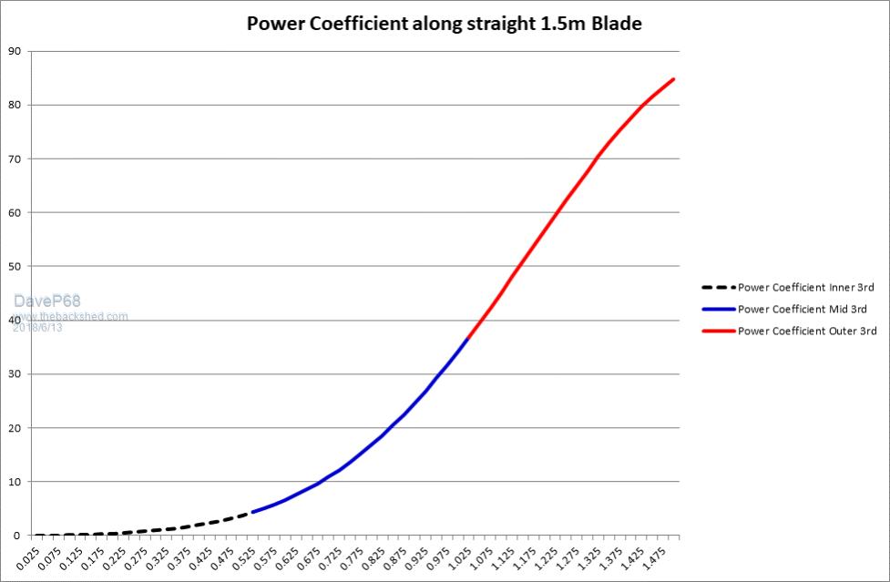 A Bar graph showing the power output percentage of each 0.5 m section along the 1.5 m blade from inner to outer.  So as can be seen the inner 0.5 m section of blade is producing only 1.4% of the total power. The middle 0.5 m section is 20.3% which is still significant. The outer 0.5 meter section is producing a whopping 78.3 % of the total. Took a bit to crunch the numbers on this and I'm confident that they are close to what is happening in real world conditions. This data endorses the amazing performance of the GOE 222 aluminium blade profile. On a separate note for James, here is some info published by NASA on Aerofoils. 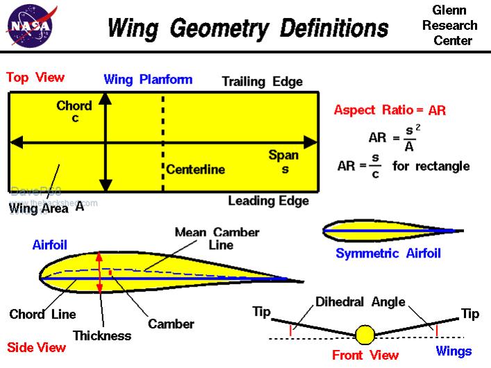 The trick is to try and profile the outer half of the PVC blades to follow a profile close to what's shown above. This may require a small reduction in the Chord line. Hope this helps to clarify how one type of blade works on small wind turbines. There are realities if you do not accept, will lead to frustration because you will be spending time on wrong assumptions and the results cannot follow! The Dunning Kruger Effect :) |
||||
Madness Guru Joined: 08/10/2011 Location: AustraliaPosts: 2498 |
I get worried when people agree with me  There are only 10 types of people in the world: those who understand binary, and those who don't. |
||||
| BarkyJ Senior Member Joined: 26/04/2018 Location: New ZealandPosts: 114 |
Thanks for the info guys. The tricky part is applying this to a pipe, and understanding it for that matter, haha :) I'll keep going on the path I am on, and hopefully it comes close. Been extremely busy with work, so haven't had a lot of time to play with this, but I am doing a bit of blade grinding each evening. 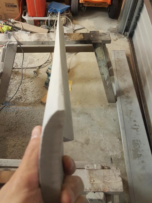 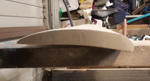 Still very much a Work In Progress |
||||
Madness Guru Joined: 08/10/2011 Location: AustraliaPosts: 2498 |
When you are getting close to the final shape you could mount the blades on the hub and balance it as you do the final shaping. There are only 10 types of people in the world: those who understand binary, and those who don't. |
||||
| DaveP68 Senior Member Joined: 25/11/2014 Location: New ZealandPosts: 292 |
Your welcome James. Like I stated above "The trick is to try and profile the outer half of the PVC blades" as that is where at least 93% of the power is produced and the outer 3rd accounts for 78.3% by my calculations. Detailed profiling of the inner half of the blade is a bit of a spent force at it only contributes about 7% to the overall output power. One more question I haven't seen come up in this topic, is blade weight. As these blades are crafted from a solid 18 mm cross section PVC pipe wall what does each blade currently weight in kg's? My rough estimation is each blade will weigh roughly 5 kg's each, depending on how much material has been removed for shaping so far. Reason I bring this up is each blade will have a Centrifugal force acting on the hub of around 2100 kg's at 500 RPM. Here is an online tool to help you work out blade loading Centrifugal force Calculator If you follow the NASA Airfoil closely over the blades length this will help reduce some of the blade weight. The point I made above about the outer half being more important is more to do with how symmetrical the profile needs to be. The trailing edge of the blade should have 25 % of the overall material going by the NASA profile and end at a sharpish point which I can see is already there. There are realities if you do not accept, will lead to frustration because you will be spending time on wrong assumptions and the results cannot follow! The Dunning Kruger Effect :) |
||||
| BarkyJ Senior Member Joined: 26/04/2018 Location: New ZealandPosts: 114 |
I'll go weigh a blade shortly. Just have to go back to work. Yep, one edge is sharp from about 1/4 down to the tip. The end of the tip is still pretty solid, so I need to take some meat out of that. Unsure exactly how the tip end should be though. Somewhat rounded to match the 3m or so diameter I assume, but in terms of thickness I assume it needs to be thinned to be somewhat sharp at the tip too (not the edge I already have sharp, but the end) |
||||
| brucedownunder2 Guru Joined: 14/09/2005 Location: AustraliaPosts: 1548 |
One of my plastic blades sort of warped,bent. Toward the end area. Could have been sunlight ,dunno. Tried bricks ,weights, on affected area,but bend was ,is , permanent. Bruce Bushboy |
||||
| yahoo2 Guru Joined: 05/04/2011 Location: AustraliaPosts: 1166 |
Not a good idea to assume anything, making a blade look like a wide wing or high speed prop might not provide any benefits. rounded prop tips are usually made to prevent the flow around the blade end from exceeding mach 1, plenty of low speed planes have very little taper or rounding. it is possible for high pressure air to move from the back of the blade around the end of the tip and create a trailing vortex that will increase drag. I dont remember if we had a solution or a theory about that. the problem I saw the most is the incorrect angle of attack (or a poor blade shape) that caused the (low pressure) laminar flow over the top face of the blade to tear off randomly. Sometimes as a low cost quick fix I used whipper snipper cord and some propeller tape to make a fixed line for the low pressure air to get a clean consistent break-away. I'm confused, no wait... maybe I'm not... |
||||
| DaveP68 Senior Member Joined: 25/11/2014 Location: New ZealandPosts: 292 |
My point regarding ending in a "sharpish point" relates only to the entire "trailing edge" along the blade length. I wasn't making any reference to the end of the blade. The end of the blade needs to have the profile of the airfoil. There are realities if you do not accept, will lead to frustration because you will be spending time on wrong assumptions and the results cannot follow! The Dunning Kruger Effect :) |
||||
| BarkyJ Senior Member Joined: 26/04/2018 Location: New ZealandPosts: 114 |
Blades are approximately 4.5KG each, at the moment. But still more trimming to go. I'll leave the ends like an airfoil. @Yahoo2 do you happen to have a picture of what you did with the whipper snapper cord? Really curious to see. |
||||
| Warpspeed Guru Joined: 09/08/2007 Location: AustraliaPosts: 4406 |
*** ding ding *** we have a winner. [quote]the problem I saw the most is the incorrect angle of attack (or a poor blade shape) that caused the (low pressure) laminar flow over the top face of the blade to tear off randomly. [/quote] This is the whole basis of understanding how airfoils and airflow work. Overall shape is only the icing on the cake, the vital ingredient is the angle of attack, and its most important right at the leading edge. Once the air detaches and becomes turbulent, all you then have is drag and no thrust, so its important to move the point of flow separation as far back towards the trailing edge as possible. If you stuff it up right at the leading edge, its a complete waste of time carefully shaping the rest of the blade if its in turbulent air. Wool tuft testing is the best way to test an aerodynamic shape in moving air. https://www.youtube.com/watch?v=ClvoZNdVwJs These days should be possible to mount a small TV camera onto a blade and watch the fun in real time. Cheers, Tony. |
||||
| DaveP68 Senior Member Joined: 25/11/2014 Location: New ZealandPosts: 292 |
*** ding ding *** nothing about winning here in my view. Concentrate on that outer 3rd of the blades when it comes to all of the above... There are realities if you do not accept, will lead to frustration because you will be spending time on wrong assumptions and the results cannot follow! The Dunning Kruger Effect :) |
||||
| Warpspeed Guru Joined: 09/08/2007 Location: AustraliaPosts: 4406 |
Oh I think a successful project can be viewed as a personal win. Cheers, Tony. |
||||
Madness Guru Joined: 08/10/2011 Location: AustraliaPosts: 2498 |
This Calculator from Warlock Engineering is very comprehensive and should give you correct angles and cross section. There are only 10 types of people in the world: those who understand binary, and those who don't. |
||||
| yahoo2 Guru Joined: 05/04/2011 Location: AustraliaPosts: 1166 |
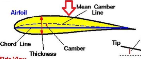 no photos. Usually the line would be forward of the arrow I have marked. I would superglue it on, test it, when we were happy with the diameter of the filament and the position add a bit of filler and tape it down. It is kind of hard to explain, you are trying to max the lift and minimize the drag, sometimes a very thin layer of turbulent air gives a lower drag number than trying to "stick" a laminar flow right to the tail. Think golf ball, car rear boot lip, vortex generators. The shape of the leading edge dictates the % split of air going over and under the blade, plus the natural turbulence in the air the wind turbine is running in plus the load on the generator slowing the rpm, that all changes the position of the line. I had prop tape with me most times because insect impacts would damage the edge of some blades and it was a quick fix. I might have a photo of a really nice Chinese blade with the line molded in, it is probably archived, I am not keen to dig it out unless you really need it. I'm confused, no wait... maybe I'm not... |
||||