
|

|
Forum Index : Electronics : Experimental sinewave inverter designs
| Author | Message | ||||
| Tinker Guru Joined: 07/11/2007 Location: AustraliaPosts: 1904 |
I might modify one of the larger Aerosharp chokes which appears to be wound this way but with too small wire for reasonable power. How few turns of bigger area wire do you think would do the trick? Klaus |
||||
| Warpspeed Guru Joined: 09/08/2007 Location: AustraliaPosts: 4406 |
I really cannot answer that Klaus, but your inductance tester might give you some idea of what to expect. Cheers, Tony. |
||||
| tinyt Guru Joined: 12/11/2017 Location: United StatesPosts: 438 |
I applied the code change to your original Atmel Studio compatible code and scoped the OCR1A and OCR1B outputs. The soft start takes about 11 seconds to complete. CH1(Yellow) is OCR1A output and CH2(Green) is OCR1B output. For the SPWM captures, the 'scope is bandwidth limited so I did not have to use the RC network at the probe tip. 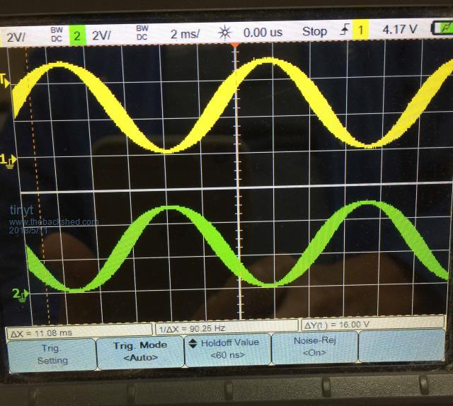 I transferred the CH1 probe to the PORTD7 pin and triggered on CH1. With scope cursors function, I measured the frequency of the CH1 pulses and it measured 90 Hz instead of 50 Hz. Maybe the code needs some minor adjustments. 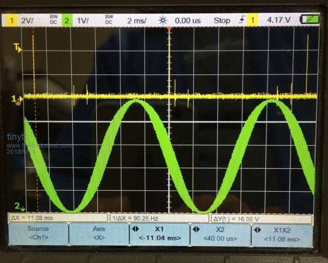 I played with NPWM value and when I changed it from 400 to 720, the scope measured 50 Hz. And when it is 600, the scope measured 60 Hz. I almost failed in math during my school days, so I really don't know what the code is doing. |
||||
| Warpspeed Guru Joined: 09/08/2007 Location: AustraliaPosts: 4406 |
Oh yes lovely! Cheers, Tony. |
||||
| poida Guru Joined: 02/02/2017 Location: AustraliaPosts: 1419 |
Tinyt: I attach modified code that outputs 2 sine waves out of pins 9 and 10 which are connected to TIMER1. Changes to the code include: clearer illustration of output frequency setup #define NPWM 400 // 400 pulses for a full sine wave #define PPWM 799 // clocks per pulse (Arduino timer uses 1 x system clock, 16 MHz) // so (16e6 / 800) / 400 = sine wave output freq. = 50 Hz. // for 60 Hz, PPWM = 666 ... 59.9816 Hz using DSO freq counter // for 50 Hz, PPWM = 799 ... 50.0096 Hz a full sine wave pulse width lookup table. Since a sine wave goes negative, we need to offset it by +1. Now it is 2x too big, so the scale becomes 8192 for(t=0.0,i=0; i <= NPWM; i++,t += 2.0 * 3.14159/ (float) NPWM) { u = 8192.0 * sin(t); l = 8192 + (int)u; } A simpler TIMER2 overflow routine: ISR(TIMER2_OVF_vect) { TCNT2=100; uf=1; if(oen == 1) sbi(PORTD,5); else cbi(PORTD,5); check_switch(); } More complex TIMER1 overflow, due to needing a 180 deg offset waveform output. ISR(TIMER1_OVF_vect) { long c,d; unsigned int p2; c = (l[pcount] * vpwr) >> 14; // scale sin wave by vpwr 32 bit integer calcs. OCR1A = c; p2 = pcount + NPWM/2; if (p2 >= NPWM) p2 -= NPWM; d = (l[p2] * vpwr) >> 14; // scale sin wave by vpwr 32 bit integer calcs. OCR1B = PPWM - d; pcount++; if(pcount >= NPWM) { pcount = 0; sbi(PORTD,7); // give a sync pulse for DSO, aligned with start of 50Hz cbi(PORTD,7); } } Since TIMER1 now has to produce 2 output signals on two pins (pins 9 and 10) we need to enable pins 9 and 10 for output now. //pinMode(9, OUTPUT); sbi(DDRB,1); //pinMode(10, OUTPUT); sbi(DDRB,2); And the attached code works on my Arduino Uno, using an AVR ISP II and Atmel Studio 7. Press the button (pin 8 puled to ground) and you get two nice sine waves at 50 Hz. Amplitude ramps up from zero to 5 V in 3 seconds. 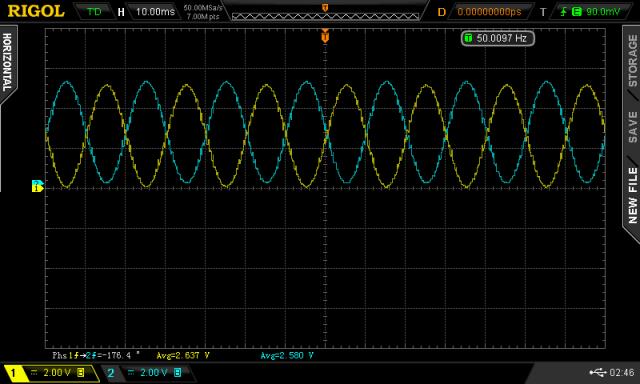 2018-05-11_093826_sinex2.zip wronger than a phone book full of wrong phone numbers |
||||
| Warpspeed Guru Joined: 09/08/2007 Location: AustraliaPosts: 4406 |
All we need now is for someone to try this on a working inverter to see if it makes the kinks and wobbles vanish. Cheers, Tony. |
||||
| poida Guru Joined: 02/02/2017 Location: AustraliaPosts: 1419 |
I probably will on the weekend. I'm playing with variable frequency now. 5 to 80Hz output controlled by a pot. wronger than a phone book full of wrong phone numbers |
||||
| tinyt Guru Joined: 12/11/2017 Location: United StatesPosts: 438 |
Thanks poida for the detailed explanation. Looks like I picked up the wrong #defines: And in the first zip of the Atmel Studio compatible code: * GccApplication2.c * * Created: 20/04/2018 9:49:15 AM * Author : w7-64-vm */ #include <avr/io.h> #include <math.h> #include <avr/interrupt.h> #define cbi(sfr, bit) (_SFR_BYTE(sfr) &= ~_BV(bit)) #define sbi(sfr, bit) (_SFR_BYTE(sfr) |= _BV(bit)) #define NPWM 400 #define PPWM (160000 / NPWM) uint8_t f50,oen; Using this now makes the frequency good in the NANO/STK500 setup I am using. #define NPWM 400 // 400 pulses for a full sine wave #define PPWM 799 // clocks per pulse (Arduino timer uses 1 x system clock, 16 MHz) // so (16e6 / 800) / 400 = sine wave output freq. = 50 Hz. // for 60 Hz, PPWM = 666 ... 59.9816 Hz using DSO freq counter // for 50 Hz, PPWM = 799 ... 50.0096 Hz I wish I can test in hardware. My inverter is still un-finished and I don't even know if my inverter circuit can do bipolar. Don't we need a total of four SPWM signals? |
||||
| poida Guru Joined: 02/02/2017 Location: AustraliaPosts: 1419 |
Tinyt: This code produces 2 outputs only, and each of these needs to be fed into a 1/2 bridge gate drive IC such as IR21844. These and other drive ICs produce the low and high side gate drives, with the needed dead time, from one input. The inverters we have all been making here use the IR2110 which takes two inputs, and expects the two inputs to have dead time present if you need dead time on the outputs. Warpspeed of course does not need the IR2110 at all since his inverter is a different beast altogether. wronger than a phone book full of wrong phone numbers |
||||
| tinyt Guru Joined: 12/11/2017 Location: United StatesPosts: 438 |
Hi poida, So right now with this code, we cannot use the IR2110/IR2010 version of the inverter? |
||||
| poida Guru Joined: 02/02/2017 Location: AustraliaPosts: 1419 |
Tinyt, no we can't. I suppose that is a problem. I just tried the 2x SPWM drive with my prototype inverter. It works. No blowups. yet. I had to modify the code to give a slow ramp down when switching off, else I got a load "click" when gate drive ICs were turned off. It runs very smooth now, on ramp up to set point, cruise and loads switching, and ramp down when turning it off. Under load of about 500W it produces a nice waveform. 2.8% THD 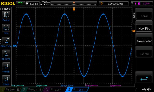 idle, not so flash 4.2% THD 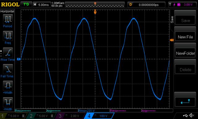 A not unexpected but welcome thing: The primary inductor runs silent now with the 2x sine PWM drive. (I obtained the THD from running a FFT on a waveform, got the peaks in volts at 50Hz, 100Hz, 150Hz etc up to 9th harmonic. Used an online THD calc aid) wronger than a phone book full of wrong phone numbers |
||||
| tinyt Guru Joined: 12/11/2017 Location: United StatesPosts: 438 |
WOW. After I get my inverter running regular unipolar, I will see if I can make trace cuts and jumpers to run it bipolar. I hope it will not take years to do it. LOL Have you tried the external sync? |
||||
| Warpspeed Guru Joined: 09/08/2007 Location: AustraliaPosts: 4406 |
It looks like one of those harmonics, possibly the third, is exciting some wobbles just after the zero crossing but it appears to damp out fairly quickly before the next zero crossing starts it up again. . Cheers, Tony. |
||||
| zaphod Regular Member Joined: 03/06/2018 Location: United KingdomPosts: 93 |
Hi all, great thread but I am not sure if us ferrite people are allowed in this thread of iron guys ? (we are a bit delicate) :) I write in assembler on a PIC24EP that runs 70Mips on a good day, I find this processor and language particuarly exacting and saves my feet straying to far from the ground :) My sine table is just 90 degrees and 5 bit (whoaa thats right 5 bit). A timer ISR running at ~6.4Khz (50*4*32) outputs this to a 10 bit DAC via a 5*5 multiplier, the other 5 bits coming from a power control function. The resulting DAC output compared with a certain 110Vrms referance signal is shown in the attached scope shot (phase & frequency locked). As for the resolution I consider it more than adequate compared with all the non-linearities and distortions that occur downstream of the DAC referance caused in part by the power stage and in part by the loads :) As for harmonics I live in an industrial rural area so a high impedance source (long lines) combined with high power electronic drives just about maxes them out without any contribution from me :) Of course the principle of referance source is the same for ferrite or iron power stages. 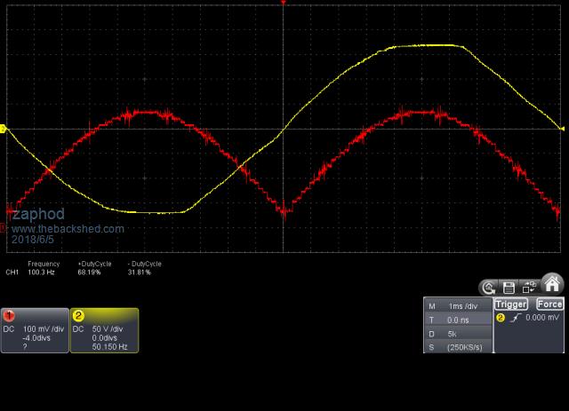 Cheers Roger 1Kwp DIY PV + Woodburner + Rainwater scavanger :) |
||||
| noneyabussiness Guru Joined: 31/07/2017 Location: AustraliaPosts: 513 |
Hi zaphod and welcome. . The reason for the big iron transformer it for off grid use it has a very LARGE surge current rating (virtually no difference in impedance to the street supply) compared with the purely switching based inverters with have a limited surge rating... im unsure where the comment is but Oztules (legend on here) has a much better explanation.. I think it works !! |
||||
Madness Guru Joined: 08/10/2011 Location: AustraliaPosts: 2498 |
Oztules will be able to explain it better than me but I will have a go. The reason the low frequency type inverter with the big transformer is better is surge capability. HF Inverters with small transformers convert the incoming DC to a higher voltage using a high-frequency converter into a capacitor bank. The only surge ability with this type of inverter is what is stored in the capacitor bank. low-frequency inverters have available all the power in the battery bank at any time. Because of this the LF inverters can handle surge current many times greater than the continuous rating. There are only 10 types of people in the world: those who understand binary, and those who don't. |
||||
| Warpspeed Guru Joined: 09/08/2007 Location: AustraliaPosts: 4406 |
Madness has nailed it... If you build say a 2Kw high frequency switching power supply to first generate a high dc voltage, and then use PWM to generate a sine wave from that high dc voltage, you are always going to be limited by that 2Kw dc to dc converter. You cannot suddenly draw 3Kw from it to supply some momentary power surge. There will only ever be 2Kw of dc available. Now a great steel lump of a transformer driven with PWM straight from a battery is only limited in power by heating of the wire in the transformer, and by the maximum safe current capacity of the mosfets driving that transformer. Although constant continuous long term power output may still be limited to 2Kw (in this example) you could draw short term power surges of multiples of 2Kw for very short periods without any problem at all. If you want an inverter that has some real balls, a big lump of iron for the transformer core has all the advantages for a practical inverter. Cheers, Tony. |
||||
| zaphod Regular Member Joined: 03/06/2018 Location: United KingdomPosts: 93 |
Hello all and thank you for your kind explanations :) I believe you have a tried and tested design there that everybody trusts. I was just interested in the sine purity and how many steps where really necessary. Unlike you guys I am chicken (or lack resources) to go fully off grid so the grid supplies my surges like motor starting loads. Also I do not have a battery bank so no source of surge power demand anyway. I store my energy as heat (hot water) so my inverter is really light duty. Interesting comments though about the inverter structure, not all HF inverters have energy storage on the grid side, mine doesnt! I have 100hZ ripple capacitors on the DC input side and the power stage is like a class D audio-amp with a ferrite output transformer followed by something I call an Unfolder, a sort of controlled unrectifier that converts the transformers rectified unipolar output into a bipolar grid! Sorry if thats a bit wordy but I think quite different to your OZ-inverter. As for transformer surge capacity certainly the ferrites have a bit more of a violent saturation knee than iron (see attached picture) and so more troublesome to accomodate heavy surges (the transformer would have to be designed for the surge flux density to avoid saturation). Having said all that I get 2Kw peak from something smaller than my fist at 25Khz (very conservative) and I know I can push it a lot harder when I want to...... Given the weather conditions here in the UK it's hard to envisage off grid on PV alone and I have already determined through an experimental installation that the plot is to small for small wind (to much turbulance and rules limiting the tower height), a small stream has only a 3 inch fall over my land so I am really up against it for renewable energy sources :) Sorry if I am polluting the thread...... 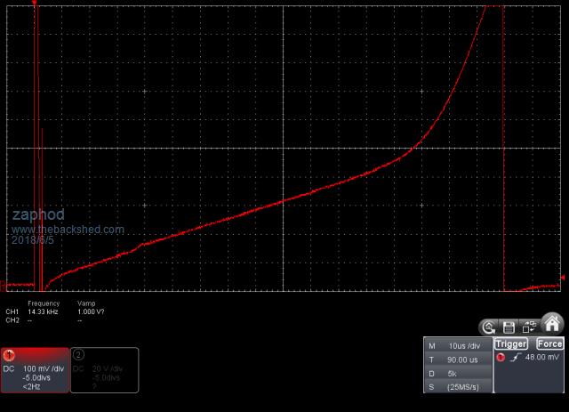 Cheers Roger 1Kwp DIY PV + Woodburner + Rainwater scavanger :) |
||||
| Warpspeed Guru Joined: 09/08/2007 Location: AustraliaPosts: 4406 |
My current system does not have a battery, it uses solar power during the day, but reverts to dc from a grid powered rectifier at night. All achieved with a single diode. During an Australian summer I get about 80% of my total power from solar. During winter it falls to about 55% from solar. A battery will fix that, as there is easily sufficient total solar power, even in mid winter, its just that it drops to zero at night no matter how many solar panels there are. Anyhow, a three inverter stepped system with 27 steps produces about 4% harmonic distortion, about the same as measured off the the grid. A four inverter stepped system with 81 steps peak to peak produces 1% measured harmonic distortion without any filtering. It looks like this, straight from a wall outlet on a wide band oscilloscope at 100v per division. 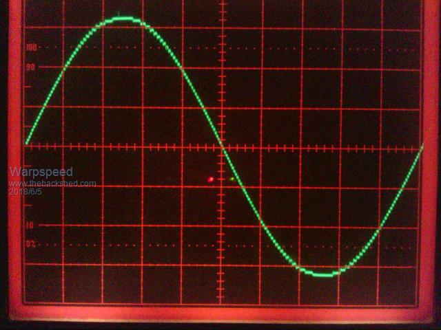 Cheers, Tony. |
||||
Madness Guru Joined: 08/10/2011 Location: AustraliaPosts: 2498 |
I know my inverter will take anything I throw at it and will trip a 20A AC breaker with overload and the inverter just carries on. I have done this trying to start a 5KW compressor induction motor while stalled, rest of the family in the house never knew it happened. There are only 10 types of people in the world: those who understand binary, and those who don't. |
||||