|

|
Forum Index : Electronics : Inverter PCB’s
| Author | Message | ||||
Madness Guru Joined: 08/10/2011 Location: AustraliaPosts: 2498 |
Are you suggesting a 2nd Thermistor on A7 Oz? or connecting into the existing? My preference is for digital temperature sensors as you have as many as you like on the one input. There are only 10 types of people in the world: those who understand binary, and those who don't. |
||||
oztules Guru Joined: 26/07/2007 Location: AustraliaPosts: 1686 |
No. Just confirming your using the voltage divider for the volt sense, and it appears to go to A7.... you have plenty of inputs for the temp sensing and the logic behind using that information for shut down. circuit looks fine to me if thats the case. I see the advantage of the nano on-board as a useful tool to monitor the current machine state, and also to predict the occurrence of a problem or whether the apparent anomaly is just a part of temporary overheating from heavy load. Battery drain for the same reason etc. You can then evaluate if it is a shut down thing, or ride it through for a few minutes to see if it is worth panicking. A lot of time, voltage will drop for reasons other than flat battery.. ie heavy load at 4am, will pull it down temporarily, when you don't want a shut down, as YOU know the batts are fine, and you are boiling the jug, while the Hot water has kicked in, and no solar because of the time. In those circumstances you are able to allow the nano to evaluate if this is low batt or just a quirk of usage. So now you can shut down from temp, current, battV and anything else you can dream up is worthy of shut down, or just monitor it further and then maybe shut down... sky is the limit with this addition... ie you might allow for 16kw for motor start, but if it continues for more than a few seconds.. something is wrong. I may have to redesign things to incorporate your nano for all of the above. You already have access to current, voltage, temp... simple input to the ADC's and you have the lot.... ie you can use it for the fan control, and get rid of the other fan boards. .........oztules Village idiot...or... just another hack out of his depth |
||||
Madness Guru Joined: 08/10/2011 Location: AustraliaPosts: 2498 |
Yes I had thought of ditching the separate fan PCB, adding the fan control would still require the separate 12V PSU. Oz do you know what voltage range you can expect from the current transformer? Would using the Nano to do an emergency shutdown be up to doing away with the SCR method? I figured in the code for voltage based shut down there would be set point where the voltage would have to fall below for a given amount of time. Then another voltage where it would shut down in a much shorter time because of a fault rather than low battery. But a current/time based shutdown is probably far better for capturing overload faults. There are only 10 types of people in the world: those who understand binary, and those who don't. |
||||
oztules Guru Joined: 26/07/2007 Location: AustraliaPosts: 1686 |
I like the scr... it stays for me. The CT is being used as a isolated supply at the moment, and to maintain that a opto coupling may be the best... or another CT. A zenner across the opto input would be wise too, and some resistance to protect that as well. Yes, we still need the 12v source for the fan/s, but we can control the pwm to then from the nano, rather than the simple comparator. Always a million ways to do the same thing. ........oztules Village idiot...or... just another hack out of his depth |
||||
| Warpspeed Guru Joined: 09/08/2007 Location: AustraliaPosts: 4406 |
You need instant shutdown using an SCR which turns off the mosfet gate drivers directly in hundreds of nanoseconds or less. By the time the software has scratched its bum, and figured out what to do, the smoke from your exploding mosfets will all have cleared away. Cheers, Tony. |
||||
Madness Guru Joined: 08/10/2011 Location: AustraliaPosts: 2498 |
There is an SCR on the PCB for that circumstance of a dead short. Although I had an oven that was playing up that was shorting out, it just tripped the 20A breaker. There are only 10 types of people in the world: those who understand binary, and those who don't. |
||||
| yahoo2 Guru Joined: 05/04/2011 Location: AustraliaPosts: 1166 |
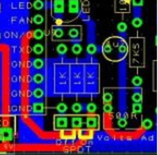
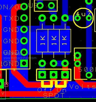
I have had one last look at your board Gary. Struggled a bit tracing all the ground tracks. went a little crosseyed. Only question I have is where is the left 1 k resistor (of the group of 3) connected, I dont really understand what it is doing.  I'm confused, no wait... maybe I'm not... |
||||
Madness Guru Joined: 08/10/2011 Location: AustraliaPosts: 2498 |
Hi Yahoo, That is the off position of the SPDT switch connects to ground via the resistor.  I will see if I can post some clearer pictures soon, just redoing a lot of the area around the Nano to include temperature sensing, fan control and current sensing. Also a slight change to the mounting holes so the TIP35c's and MOSFETs for the fan control can be flipped (if you want to) under the PCB and screwed to the +48V heatsink There are only 10 types of people in the world: those who understand binary, and those who don't. |
||||
| yahoo2 Guru Joined: 05/04/2011 Location: AustraliaPosts: 1166 |
thanks, I blew the .jpg up to 300% and I couldn't see the track to the switch. if it is any help a .gif is a little grainy but the pic can be much larger (1024 pixels wide). I'm confused, no wait... maybe I'm not... |
||||
Madness Guru Joined: 08/10/2011 Location: AustraliaPosts: 2498 |
Lots of changes around the Nano, added fan control from the Nano so the seperate fan controller is no longer required, AC current sensing and temperature sensing with DS18B20 digital sensors. This will require a separate 12V power supply the same as we are using already to drive the fans. The sensors are digital and you can have a lot of them all on one pin as each one has it's own identifying number. The current sensor is the same as already used but using a separate one so nothing interferes with the original one. The attached PDF is much easier to read and lets you zoom right in.  2018-04-22_103456_Mad_Inverter_Control_Board.pdf If you have any other pin configurations for different Isolation Transformers please post them as there is plenty of scope to add them. There are only 10 types of people in the world: those who understand binary, and those who don't. |
||||
oztules Guru Joined: 26/07/2007 Location: AustraliaPosts: 1686 |
Perhaps a low impedance load across the coil, and a zenner acros A0 to ground to protect the nano. Warp mentioned some time back, that these coils can generate very high emf under some circumstances... the low r load stops this, and the zenner makes sure. .......oztules Village idiot...or... just another hack out of his depth |
||||
| johnmc Senior Member Joined: 21/01/2011 Location: AustraliaPosts: 282 |
Pardon the dumb question ,is the yellow dot/ pad to symbolize a polarity plug? cheers john johnmc |
||||
Madness Guru Joined: 08/10/2011 Location: AustraliaPosts: 2498 |
Done 2018-04-22_121453_Mad_Inverter_Control_Board_V2.pdf JohnMc, I guess the dot is for polarity, it is not needed on the current sensor but it is a bit of a fiddle to get rid of it. There are only 10 types of people in the world: those who understand binary, and those who don't. |
||||
| Clockmanfr Guru Joined: 23/10/2015 Location: FrancePosts: 429 |
Just had a good look at your version 2. That's a tidy compact Control board and with the cooling board, and a nano board combined, very nice Madness.  Everything is possible, just give me time. 3 HughP's 3.7m Wind T's (14 years). 5kW PV on 3 Trackers, (10 yrs). 21kW PV AC coupled SH GTI's. OzInverter created Grid. 1300ah 48v. |
||||
Madness Guru Joined: 08/10/2011 Location: AustraliaPosts: 2498 |
Thanks Clockman, I have now reduced the length a bit by using shorter components for the VFB Diodes. Also I have tidied up the tracks more, unless someone finds a mistake this should be the final version to get manufactured. 2018-04-23_081023_Mad_Inverter_Control_Board_V3.pdf There are only 10 types of people in the world: those who understand binary, and those who don't. |
||||
| stevebequik Newbie Joined: 20/07/2016 Location: AustraliaPosts: 12 |
Great work madness. If I'm not too late. 2 inverter control boards 2 inverter power boards 1x GTI control board Thanks |
||||
renewableMark Guru Joined: 09/12/2017 Location: AustraliaPosts: 1678 |
Good stuff Mad, I reckon there are a few of us chomping at the bit to get them, Sing out with an updated parts list when you get a chance so we can get that ordered too. Cheers and thanks for taking the time to do this for us. Cheers Caveman Mark Off grid eastern Melb |
||||
Madness Guru Joined: 08/10/2011 Location: AustraliaPosts: 2498 |
No boards have been ordered yet so not too late, I will make a call for final numbers and payment very soon, just need to do a little more tiding up of the PV regulator PCBs. The parts list is not much different. You will need 2, 3, 4 & 5 pin 2.54 pitch PCB connectors. 2 pin 5.08 mm PCB connector (I use screw but could be plug in) 10K trim pot 100K 0.25W resistor 9k1 0.25W resistor Arduino Nano Just added a beeper also Everything else is the same parts you already have, ie diodes, caps & MOSFETs. The additional components are not required if you just want the original Oztules version. The addition of the Nano will control fans, shut down if voltage is too low, temperature is too high or current is excessive. Plus there is scope to add more functions. There are only 10 types of people in the world: those who understand binary, and those who don't. |
||||
renewableMark Guru Joined: 09/12/2017 Location: AustraliaPosts: 1678 |
Thanks Mad, nano is something new to me, ill have to watch some youtube demo's. Is this one ok? Also are they prone to going POP? Is it wise to order a couple/few? Cheers Caveman Mark Off grid eastern Melb |
||||
Madness Guru Joined: 08/10/2011 Location: AustraliaPosts: 2498 |
That Nano is correct however they are cheaper without the USB cable if you already have one. They are the same cable as many phones etc and you only need it to upload the software to the Nano. You can buy 3 here for less than the price of that one. Forgot to mention also you need an LCD Display Here is a good place to start learning about the Arduino Nano. There are only 10 types of people in the world: those who understand binary, and those who don't. |
||||