
|

|
Forum Index : Electronics : ozinverter control no sinewave
| Author | Message | ||||
renewableMark Guru Joined: 09/12/2017 Location: AustraliaPosts: 1678 |
Jesus christ John, you're not having much luck mate. I'm not feeling too confident of mine going well now. I see you are running the Clockman power board but a red control board. Could there be an issue between the two? Cheers Caveman Mark Off grid eastern Melb |
||||
Revlac Guru Joined: 31/12/2016 Location: AustraliaPosts: 1026 |
That let the smoke out. Thats why I'm not allowed to test fets in the house after my last episode. I run a small EI transformer to test with first, before using something large like the toroid, just is a little more forgiving and gives me some time to check everything. However if their is a bad joint (bad signal) it can still blow the fets if run without the series resistor and caps in. Will give mine a test run soon and fingers crossed hopefully it will work. Cheers Aaron Off The Grid |
||||
| Tinker Guru Joined: 07/11/2007 Location: AustraliaPosts: 1904 |
Oh dear, you seem to be headed down that road that myself and madness followed for a while  . .Well, myself and madness got there in the end, it was a steep learning curve and I'm glad I had to follow it in a way - experience is a very good teacher IMO. Try to get it to work with just 4 HY4008's and a smallish capacitor, maybe 4700uf or so. Test this with increasing loads, restive at first and lots of on and off switching. If it passes that try with a fridge, 4 x HY4008's should easily start & run one. Good luck Klaus |
||||
renewableMark Guru Joined: 09/12/2017 Location: AustraliaPosts: 1678 |
John, you seem to have gone through so many fets and three different board, ordered completely new parts from different suppliers it's hard to understand what's going on. Could it be possible it's the torroid? Cheers Caveman Mark Off grid eastern Melb |
||||
Madness Guru Joined: 08/10/2011 Location: AustraliaPosts: 2498 |
That must be very disheartening John. If you can run it with no caps and a resistance till you get all the waveforms correct you should not have anything blow. I would fit just 4 FETs like Tinker mentioned, you can run 10 Amp AC load on just 4 for a while so you can give it a good test like that. Where are you buying your FETs from? I have not had one bad one from https://www.aliexpress.com/store/product/100-New-original-MOSFET-HY4008-HY4008W-80V-200A-TO-3P-inverter-Ultra-chip/23830 59_32731860389.html Also if you are blowing MOSFETs apart, damaging PCB's and other components your breakers are too high of a current rating. I would stick to a maximum of 80A DC breaker. Can you get it running with 4 FETs, no caps, a series resistance and no load? When you do please post CRO shots of the 8 test points below. Ignore the IR2010 the pins are the same as IR2110. 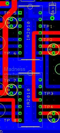 There are only 10 types of people in the world: those who understand binary, and those who don't. |
||||
Madness Guru Joined: 08/10/2011 Location: AustraliaPosts: 2498 |
John did you have the earth lead of CRO connected to ground, all the little spikes there are not normal. I am wondering if there are crook capacitors. There are only 10 types of people in the world: those who understand binary, and those who don't. |
||||
Madness Guru Joined: 08/10/2011 Location: AustraliaPosts: 2498 |
Link above for MOSFET supplier does not work. Use this LINK. If you only want 20 use this LINK INSTEAD. There are only 10 types of people in the world: those who understand binary, and those who don't. |
||||
renewableMark Guru Joined: 09/12/2017 Location: AustraliaPosts: 1678 |
John if you need some fets I just got 100 from that supplier. You may be inclined to wait for Mads boards to proceed though. Sorry to see you go through that mate  One other thought, I found some components were miles out of spec when tested, some mono caps were 1/5th of their advertised value, so maybe completely check EVERYTHING. I ended up buying replacements from alltronics and jaycar, everything from these two was spot on. Considering the inconvenience of a failed project I think it's actually smarter and cheaper in the long run to pay the exorbitant prices for the added quality. Cheers Caveman Mark Off grid eastern Melb |
||||
Madness Guru Joined: 08/10/2011 Location: AustraliaPosts: 2498 |
The boards John has should be fine, I suspect his FETs are the problem. When I stopped buying cheap ones from other suppliers things got much better for me. Keep in mind some components from China are rejects that don't come up to spec. Very true but I think you can get reasonably priced quality components if you do your research. One other factor is the mental toll it takes on you when things are going wrong. There are only 10 types of people in the world: those who understand binary, and those who don't. |
||||
| johnmc Senior Member Joined: 21/01/2011 Location: AustraliaPosts: 282 |
Good day All, Thank you all for the kind words  I have just checked my supplier of the HY4008 and they are the same supplier that Madness suggested (Aoweziic 100% New original MOSFET HY4008) The transformer is from another inverter that did work. Thanks for the Fet offers Mark but I still have 90 odd HY4008 fets yet to sacrifice  , these fets are from the same supplier as Madness uses, , these fets are from the same supplier as Madness uses,I have tried IR2110's from RS but they did not solve the problem But hope that the square wave output from the IR2110 can be improved and remove the hash from the fet gate's cheers john  johnmc |
||||
| johnmc Senior Member Joined: 21/01/2011 Location: AustraliaPosts: 282 |
Good day All Thanks to oztules for the information on the hash causing problems with the on off leads. I now have working   , one of madness, new pcb control board, that has been modified as suggested by tinker and shown on madness updated pcb drawing this coupled with one of clockmans power board at present only one set of 4 fets and large capacitors will update when I fit 16 fets .The on off switch at the moment is attached to the pcb as per madness,s suggestion. , one of madness, new pcb control board, that has been modified as suggested by tinker and shown on madness updated pcb drawing this coupled with one of clockmans power board at present only one set of 4 fets and large capacitors will update when I fit 16 fets .The on off switch at the moment is attached to the pcb as per madness,s suggestion. I intend to fit the on off switch capacitors as per oztules suggestion when the whole system is fitted into the cabinet. Many thanks to all cheers john johnmc |
||||
| johnmc Senior Member Joined: 21/01/2011 Location: AustraliaPosts: 282 |
Good Day all The latest inverter build with madness power and control boards with no large capacitor 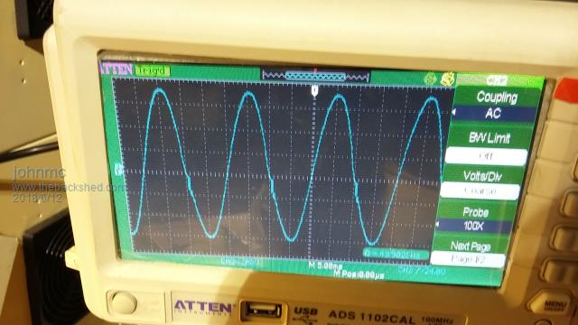 The powerboard negative rail had copper bolt soldered to the PCB 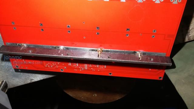 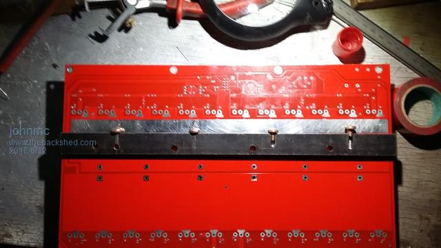 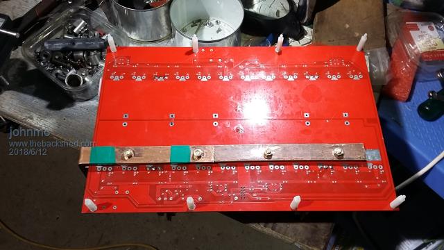 The 23.5 khz signal has spike overshoot 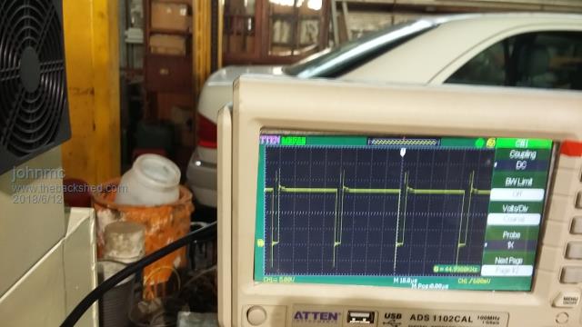 Is this a product of my scope as it does not appear to affect the output sinewave? The first build with madness new boards the power fets on the powerboard blew on startup. the fault was, a dodgy transistors (locally expensive) in the totem pole . NO damage to the control board  Replaced with cheap transistors  Await the dreaded startup with full complement of Fets and Capacitors  cheers john johnmc |
||||
| johnmc Senior Member Joined: 21/01/2011 Location: AustraliaPosts: 282 |
because of the history of Inverter blowups almost always on start up after overload or initial startup or the dreaded reset button. I have tried to make removing the powerboard as simple as possible 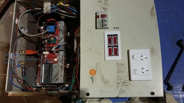 All the connections to control and power board have been brought to the top for easy access cheers john johnmc |
||||
Madness Guru Joined: 08/10/2011 Location: AustraliaPosts: 2498 |
Hi John, If you test with no big capacitors and via a resistance (I use 2 33 Ohm 10W in parallel) you should be able to test with no blowups at all. The MOSFETs can't draw enough current to harm them with the resistance in series. I assemble the PCB initially with just 4 MOSFETs and not connected to the toroid and do a test of the signals then. After that I fit all the MOSFETs with heatsinks, still without the big caps and connect it to the toroid. You won't be able to get full AC volts but by adjusting it down the inverter will run via the resistance with no load. This gives you the chance to check the waveform is good without risk. Last few I have assembled worked right away, one from that last batch of PCBs that yours came from is running our house for a few weeks now. Those extra steps may take a bit extra time but I think a bit more time spent confirming everything right is better than having a blowup and going back to square one. I know what you mean about bad components. A couple TIP42's I bought locally last year gave me trouble. I bought 100 MOSFET driver ICs recently and turns out they are all dead. There are only 10 types of people in the world: those who understand binary, and those who don't. |
||||
Madness Guru Joined: 08/10/2011 Location: AustraliaPosts: 2498 |
John, I have found a better way to reset the Inverter after an overload. Instead of grounding the 5W 120 Ohm resistor connect the wire to the 1K8 resistor as shown below. I have tested this when the Inverter is in overload state short this point to ground and the overload LED turns off and after 5 seconds the Inverter does a soft start. No need to turn off the power switch or anything else, just ground it as shown, the BT136 turns off, the EG8010 recognizes that the overload is gone and does a nice calm soft start. There should be no risk of a catastrophic blow up that a few of us have had doing a hard short. You can trigger an overload by connecting a 9V battery across the current transformer connector on the PCB if you want to test it. 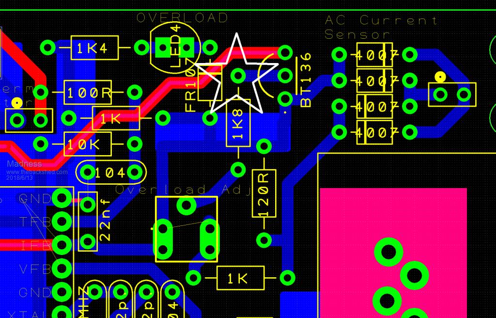 There are only 10 types of people in the world: those who understand binary, and those who don't. |
||||
| johnmc Senior Member Joined: 21/01/2011 Location: AustraliaPosts: 282 |
Thanks Gary for the information about turning the scr off,and the EG8100 doing a soft restart I have been away today and will be back in shed tonight or tomorrow. Will update on the inverter progress soon. cheers john johnmc |
||||
renewableMark Guru Joined: 09/12/2017 Location: AustraliaPosts: 1678 |
What tests are you doing there mate? Is it the normal ones on the control board or something on the actual power board? Cheers Caveman Mark Off grid eastern Melb |
||||
Madness Guru Joined: 08/10/2011 Location: AustraliaPosts: 2498 |
Testing both, I test the control board first but you can't test it properly until it is connected to the power board. 1 Check all solder joints are good 2 Check Drain-source resistance on all 4 sets of MOSFETs all should be above 1 Mohm. 3 connect power to control board without ICs and test 5 & 18V is correct. 4 turn off, fit ICs and confirm LED is working for EG8010, test output of IR2110s 5 Connect Control board to power board with 4 FETs and without caps and power through resistance, check that you are getting nice square wave and SPWM. 6 Fit remaining MOSFETs, repeat step 3 7 Connect to toroid and check Sinewave out 8 If sine wave is good connect power without resistance and run up to 1200W 9 Fit capacitors and test under load. If anything is not right sort it out before progressing any further especially running it without the resistance. It can run like crap while there is resistance in series and no caps and it won't blow the FETs. It gives you a get of jail free card to sort out the problem. There are only 10 types of people in the world: those who understand binary, and those who don't. |
||||
| Ralph2k6 Senior Member Joined: 24/09/2017 Location: AustraliaPosts: 129 |
I'll have to store that method for future reference. Ralph |
||||
| johnmc Senior Member Joined: 21/01/2011 Location: AustraliaPosts: 282 |
Good Day all As per Madness list above, Tests 1-4 all good Test 5 SPWM not quite symmetrical With 4 fets fitted toroid fitted and no restriction to the 50v power supply sinewave as previous post Test 6 all 24 FETS fitted no capacitors, 15 ohm resistor in series with 50 v battery supply No toroid fitted in the following pictures, Picture of powerboard low side Fet output 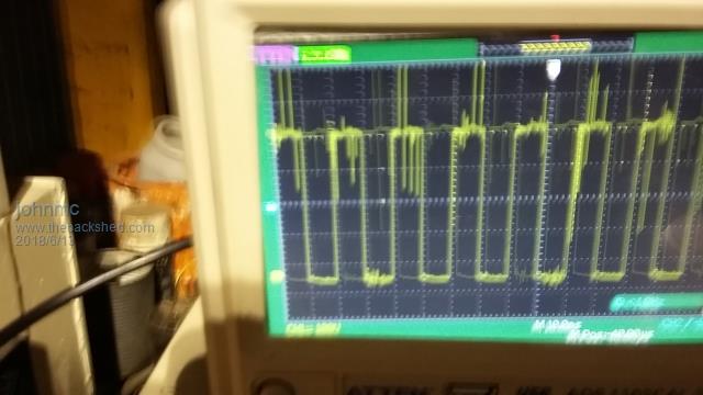 toroid low side Fet output Picture of powerboard high side Fet output 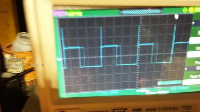 Has any one taken pictures of the powerboard with no toroid as there stil appears to be too much hash and as I have now destroyed 170 Fets I am going to be more cautious . cheers john johnmc |
||||