|

|
Forum Index : Electronics : 150V 45A MPPT - roll your own
| Author | Message | ||||
| poida Guru Joined: 02/02/2017 Location: AustraliaPosts: 1418 |
something like this: void sanity_check() { // check if battery connected, solar input exists, determine tracking mode, etc. // this is called once a second // // check for non zero current values once a minute, only in NIGHT mode and only once an hour when in night mode // if there is, increment cal_sensor_count // when it gets to 60, zero it and recalibrate // int i; if (timeout_check(6,( (track_mode == NIGHT) && ( (fabs(Iin) > 0.1) || (fabs(Iout) > 0.1) ))) { cal_sensor_count ++; if (cal_sensor_count > 60) { cal_sensor_count = 0; i = adc_average(IIN,25000); // get input current sensor offset nvd.z_iin = i; // save it i = adc_average(IOUT,25000); // etc. nvd.z_iout = i; nv(); // write to non volatile ram } } .. .. wronger than a phone book full of wrong phone numbers |
||||
| flyingfishfinger Senior Member Joined: 12/09/2020 Location: United StatesPosts: 110 |
Thinking out loud: The output side is also zero at night. The controller does require some current to run, but that is derived from a regulator connected to the battery terminals, so THAT current does not pass through the output sensor. We should be ok there. Another consideration: Since we are effectively compensating for temperature drift at night only, we would still be accumulating error during the day when it warms up. So we are only solving half the capacity problem, maybe a bit more than half if we assume that a calibration in night mode near morning and evening reduces the error relative to daytime temperatures. Can we do better? |
||||
| phil99 Guru Joined: 11/02/2018 Location: AustraliaPosts: 2135 |
I guess the most straight forward way to find the current offset is to periodically switch the MOSFETs off for a couple of seconds. The output must then be zero so the offset is whatever the current sensor is now reading. Compensate for that till the next rearing. Perhaps this could be done either at the start of a max. power scan, or once per hour. |
||||
| flyingfishfinger Senior Member Joined: 12/09/2020 Location: United StatesPosts: 110 |
That sounds like an excellent idea. I would lean towards once an hour, since we probably want to wait for the main capacitors to finish discharging before we take a measurement (i.e build in a small delay). If we did that once a minute it may reduce the efficiency of the system measurably. |
||||
| poida Guru Joined: 02/02/2017 Location: AustraliaPosts: 1418 |
I'm setting up the test system now I like the idea of an hourly recal of the offsets. Should be easy to code. wronger than a phone book full of wrong phone numbers |
||||
| flyingfishfinger Senior Member Joined: 12/09/2020 Location: United StatesPosts: 110 |
Wow you are really on it! Appreciate the willingness to work on this - it'll be good for everyone else too I think :) |
||||
| poida Guru Joined: 02/02/2017 Location: AustraliaPosts: 1418 |
done and tested. this will recal the current sensor zero every 60 minutes. It "costs" a few seconds of no charging when it runs. This version is for the I2C LCD builds mpptv5_BV_tempco_I2C_night_recal (2).zip I tested it by having the serial console open and I check the zero offsets for the two current sensors. In my case they are 127 and 124 counts for the input and output sensors I then applied a 1 Amp current through a sensor, using an isolated supply. This immediately adds 1 Amp to the displayed value. Then when recal is done, that 1 Amp is removed and not surprisingly the zero offset have changed to allow for that 1 Amp Later, I removed the 1 Amp and again recal sorted out the zero offset. For those who want to play with this, each time the recal code is run, the menu is refeshed on the console so that means we can see that it ran and we can see the new values. The code I added is // this will return true once a minute, so with the counter it will run once an hour // if night mode, easy, just calibrate // if not night mode, stop the converter, wait a bit, then cal. and then re-enable back into absorb mode // mppt mode will be enabled automatically if needed // if ( timeout_check(6,1)) { cal_sensor_count ++; if (cal_sensor_count > 60) // should be 60 for an hour. testing will have it at 2 or something { cal_sensor_count = 0; // one hour is up time to recal current sensor zero points if (track_mode != NIGHT) { //stop it buck_stop(3); track_mode = NIGHT; //wait. maybe need this to let caps equalise with battery and solar inputs dlay(2000); //recal i = adc_average(IIN,25000); // get input current sensor offset nvd.z_iin = i; // save it i = adc_average(IOUT,25000); // etc. nvd.z_iout = i; nv(); // write to non volatile ram //restart, set 60 sec timer for mppt close to 60 seconds to more quickly get to mppt scan one_min = 55; } else { // it's night mode i = adc_average(IIN,25000); // get input current sensor offset nvd.z_iin = i; // save it i = adc_average(IOUT,25000); // etc. nvd.z_iout = i; nv(); // write to non volatile ram } } } inside the sanity_check() code block wronger than a phone book full of wrong phone numbers |
||||
| flyingfishfinger Senior Member Joined: 12/09/2020 Location: United StatesPosts: 110 |
Nice!! By the way, if anyone is just pasting the new section into existing code we need to also add: - "int i" to the top of sanity_check() - "cal_sensor_count" to one of the "volatile int" declaration sections at the very top of the program. One other observation: This code does NOT have the freq_scale fix discussed a few pages back, it should be added to "init_controller()" right? Edited 2023-11-18 11:53 by flyingfishfinger |
||||
| flyingfishfinger Senior Member Joined: 12/09/2020 Location: United StatesPosts: 110 |
Also, I believe you have an error in the red part. The if statement has an extra "(", just adding this bit of code will cause compilation to fail. Edited 2023-11-18 12:00 by flyingfishfinger |
||||
| poida Guru Joined: 02/02/2017 Location: AustraliaPosts: 1418 |
FF: you ARE good thanks for finding loose ends of unfinished work of mine. i2C version with above fix for PWM frequency change bug mpptv5_BV_tempco_I2C_night_recal.zip and the serial LCD version with the new hourly current sensor offset cal (includes the fix for PWM freq change) mpptv5_BV_tempco_day_totals_current_sense_recal.zip maybe it would be good if we use these two uploads as "the current version" from now on. wronger than a phone book full of wrong phone numbers |
||||
| nickskethisniks Guru Joined: 17/10/2017 Location: BelgiumPosts: 458 |
Depending on the amount or type of solar panels attached there runs a small reverse current during the night. This could also contribute to the offset deviation. I saw the LCD displays a current if you load the input (solar panels side) with a resistor. An extra series diode or mosfet could fix that if you don't mind the extra loss. I'm currently thinking about a new controller board, An extra opamp circuit with an adjustable offset (+-2.5V) could double the resolution and possible lower the offset fault. Switching to an pin compatible lgt8f328 could also increase the 10 bit resolution to 12 bit. Without changing the code much. I have those running the lcd's with great result, I also have 1 for reading a pressure sensor in my rainwater buffer. Another problem I have is when the controller is connected to a computer or something else the Vref is on a slightly different level. I had to add An external reference to the boards to do correct calibration. |
||||
| Ziki_the Newbie Joined: 13/04/2023 Location: YugoslaviaPosts: 39 |
Did you tried to cut wire +5V in usb cable? So +5 from usb and +5v from brain board do not mix.. I did that. Pozdrav iz Srbije |
||||
| soudirector Newbie Joined: 14/05/2023 Location: NigeriaPosts: 26 |
Is the calibration the same? how times flies  |
||||
| soudirector Newbie Joined: 14/05/2023 Location: NigeriaPosts: 26 |
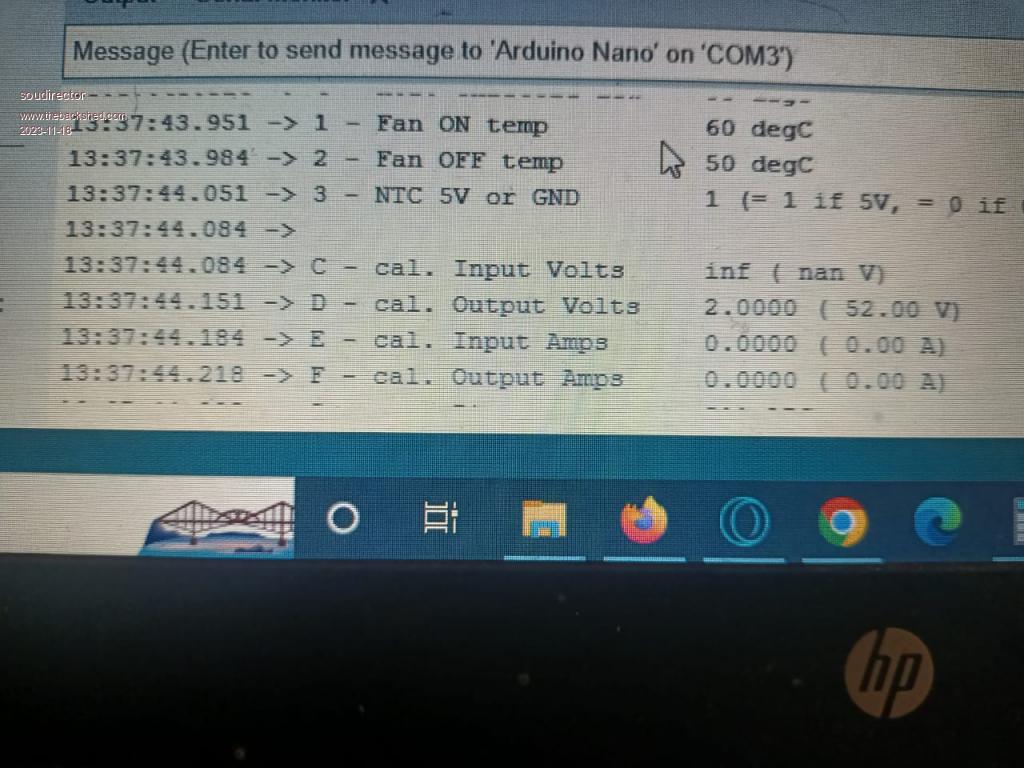
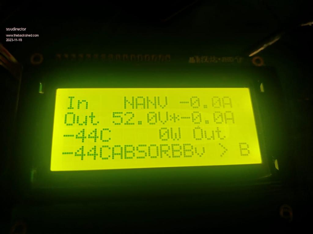
I am have not gotten this to work. When cal. i type in the VIN but i still have NANU display. in the serial monitor window it will change to this 13:37:44.084 -> C - cal. Input Volts inf ( nan V) But VOUT display whatever i put there. What am i not getting right ?   how times flies  |
||||
| nickskethisniks Guru Joined: 17/10/2017 Location: BelgiumPosts: 458 |
|
||||
| nickskethisniks Guru Joined: 17/10/2017 Location: BelgiumPosts: 458 |
Nop, that was to easy, I didn't think about doing it that way  Good suggestion, that should do the trick as Well, but doing it my way the nanoboard stays unmodified but it needs and extra line of code. Edited 2023-11-19 05:09 by nickskethisniks |
||||
| Ziki_the Newbie Joined: 13/04/2023 Location: YugoslaviaPosts: 39 |
@nick Just use usb cable for programing nano, cut insulation and cut red wire. No need for nano modification... Pozdrav iz Srbije |
||||
| nickskethisniks Guru Joined: 17/10/2017 Location: BelgiumPosts: 458 |
Just use usb cable for programing nano, cut insulation and cut red wire. No need for nano modification... I would probably come up with that in my sleep this night, but at the moment I was writing I couldn't see the most obvious solution...thanks for making me blushing again. I hope I can score some points again to honor my "guru" status.  |
||||
| Ziki_the Newbie Joined: 13/04/2023 Location: YugoslaviaPosts: 39 |
@nick This was quick and dirty solution, maybe will help someone else. And guru status is deserved, no blush   Pozdrav iz Srbije |
||||
| mab1 Senior Member Joined: 10/02/2015 Location: United KingdomPosts: 209 |
in the serial monitor window it will change to this 13:37:44.084 -> C - cal. Input Volts inf ( nan V) But VOUT display whatever i put there. What am i not getting right ? I think had something similar - one of the cal values 'inf' and wouldn't reset: i think i cleared it by selecting the 'set defaults' (option Z?), but this does mean you have to re-do all the zeros, cals and setpoints again. |
||||