
|

|
Forum Index : Electronics : 150V 45A MPPT - roll your own
| Author | Message | ||||
| mab1 Senior Member Joined: 10/02/2015 Location: United KingdomPosts: 209 |
You need to know what its inductance is in uH and, more importantly, what is its saturation current? Hard to tell from the picture, but it looks too small to handle 45A. If course if the saturation current is lower you could limit the mppt to match the inductor, but you still need to know what it is. |
||||
| soudirector Newbie Joined: 14/05/2023 Location: NigeriaPosts: 26 |
Can someone please educate me on who to calibrate this mppt because i am stuck there. I need a step by step on how to accomplish that. I have already the build the brainbox and power board. i don't want my money and effort to be a waste. how times flies  |
||||
Revlac Guru Joined: 31/12/2016 Location: AustraliaPosts: 1024 |
This might help, https://www.thebackshed.com/forum/ViewTopic.php?TID=15935&P=2 Edited 2023-09-01 20:08 by Revlac Cheers Aaron Off The Grid |
||||
| soudirector Newbie Joined: 14/05/2023 Location: NigeriaPosts: 26 |
https://www.thebackshed.com/forum/ViewTopic.php?TID=15935&P=2 thanks Revlac, i appreciate. i am now getting the scope on to calibrate. The only things i need to calibrate are the Vin, Vout, Iin and Iout. the rest should leave at default? Edited 2023-09-02 12:44 by soudirector how times flies  |
||||
| mab1 Senior Member Joined: 10/02/2015 Location: United KingdomPosts: 209 |
I think i may have discovered a possible 'bug' in MPPTv5_BV_tempco_day_totals ?  At the very end of Void init_controller there's this bit of code: if (nvd.pwm_freq != 20 && nvd.pwm_freq != 40) { // set default at 20 kHz timer1_period = 833; baud_waits = 1; ints_second = 19200; freq_scale = 1; } else { timer1_period = nvd.timer1_period; baud_waits = nvd.baud_waits; ints_second = nvd.ints_second; freq_scale = 2; } If my reading is correct(?!), then if nvd.pwm_freq == 20 it will actually set freq_scale = 2 instead of 1 I dug this up as i seemed to be getting radically longer delays at 20kHz than at 40kHz, and noticed freq_scale = 2: void dlay(int n) { int d; if (freq_scale == 2) d = n * 8; else d = n; dlay_timer = 0; // a simple delay loop that uses the 20kHz pwm interrupt as a clock while(dlay_timer < d) ; // This while loop will only exit if pwm interrupt is working. } Trouble is,i've hacked my version of the code so much i'm not sure what i've messed up, but that appears to be in the original code. 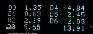 I'm still not sure how i did this to the day 4 total  |
||||
| poida Guru Joined: 02/02/2017 Location: AustraliaPosts: 1418 |
Hi Mab1 you have found a bug. This is good, I can fix it for us. Thanks for that. we need to apply the correct frequency scale factor which is used in a few places in the code. The fix is in Red if (nvd.pwm_freq != 20 && nvd.pwm_freq != 40) { // set default at 20 kHz timer1_period = 833; baud_waits = 1; ints_second = 19200; freq_scale = 1; } else { timer1_period = nvd.timer1_period; baud_waits = nvd.baud_waits; ints_second = nvd.ints_second; if ((nvd.pwm_freq == 20) freq_scale = 1; else freq_scale = 2; } the next bit also seems an error and likely a remnant of testing something or other. void dlay(int n) { int d; if (freq_scale == 2) d = n * 8; else d = n; dlay_timer = 0; // a simple delay loop that uses the 20kHz pwm interrupt as a clock while(dlay_timer < d) ; // This while loop will only exit if pwm interrupt is working. } change this to void dlay(int n) { int d; d = n * freq_scale; dlay_timer = 0; // a simple delay loop that uses the 20kHz (or 40 kHz) pwm interrupt as a clock while(dlay_timer < d) ; // This while loop will only exit if pwm interrupt is working. } here is the updated code mpptv5_BV_tempco_day_totals.zip wronger than a phone book full of wrong phone numbers |
||||
| Ziki_the Newbie Joined: 13/04/2023 Location: YugoslaviaPosts: 39 |
Today I played with fire, the result is extremely unusual. The original choke(epcos) was 1.4mH from the motor inverter 11KW. An iron torus cut in half. I will try to wound some wire and give a litle test. Did someone stumped on something lile this? 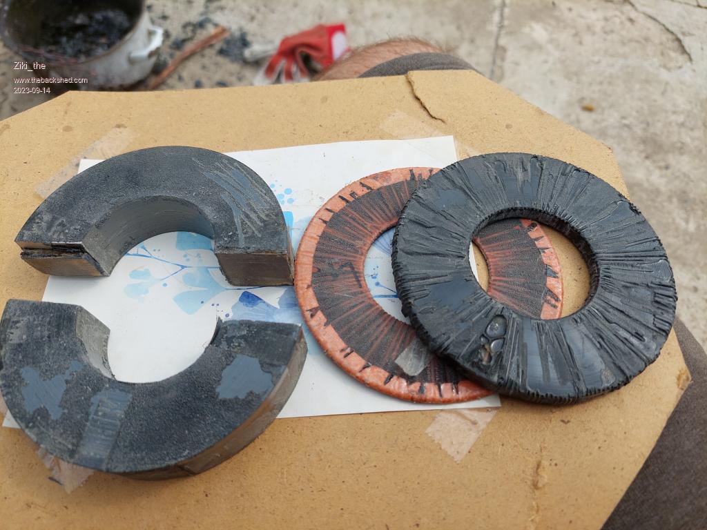 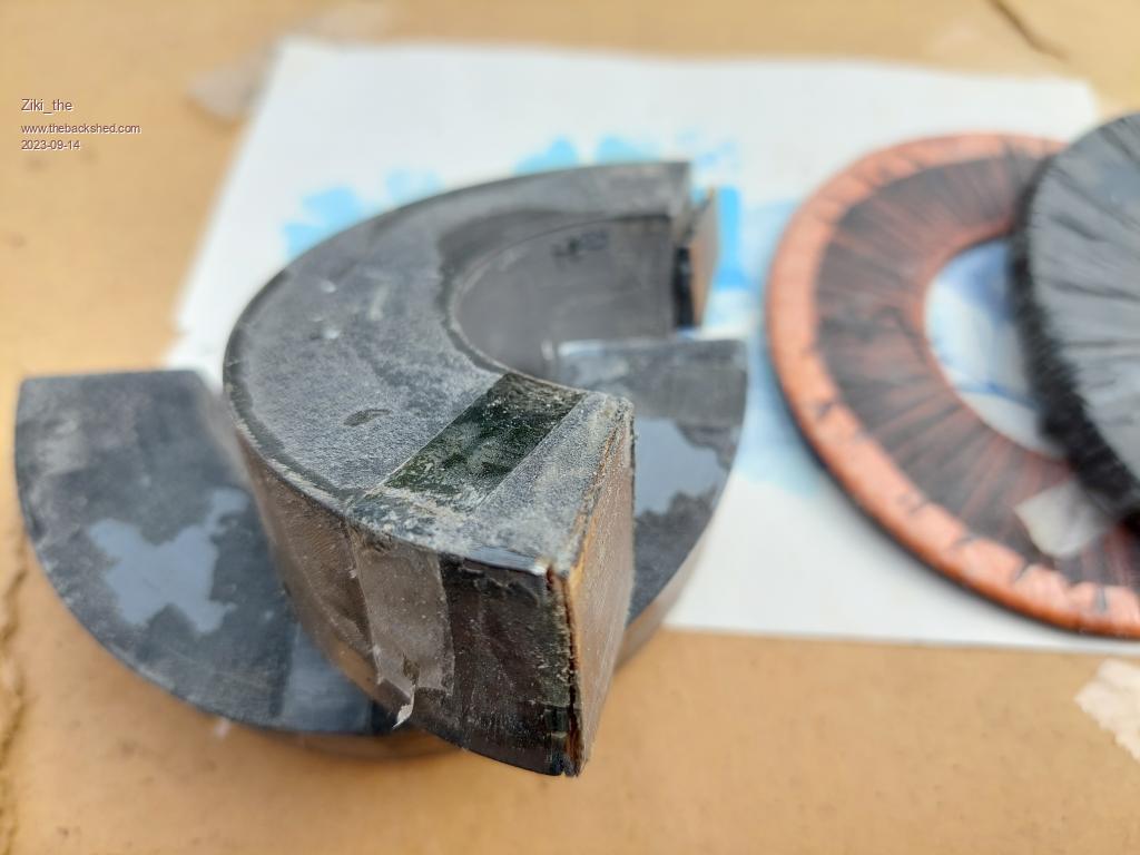  Thanks  Pozdrav iz Srbije |
||||
| andymc70 Regular Member Joined: 30/06/2019 Location: AustraliaPosts: 43 |
Hello All Just had another 2 IRBF4110 fail on my MPPT's, i just notice they are only rated to 100V VDSS, i just wondering if i can replace them with irbf4115, these are rated to 150v VDSS. But the gate voltage is only at 5V, whereas the 4110 is at 20. I am unsure of the gate voltage required or if 5V is not enough. Its also weird that the 2 IRBF's where on different MPPT's connected to the same battery. Thanks Andy Edited 2023-09-16 22:01 by andymc70 |
||||
| Ziki_the Newbie Joined: 13/04/2023 Location: YugoslaviaPosts: 39 |
@andy Yes you can use irbf4115, gate voltage for them is -+20V. This mppt give out to gate 12V max. For dead mosfets, only one per board died? All best. Edited 2023-09-16 22:17 by Ziki_the Pozdrav iz Srbije |
||||
| Tribal Tronix Newbie Joined: 14/09/2023 Location: NigeriaPosts: 6 |
Just did a speed read on this thread. Wow is all i could say. Please which code has the i2c on the main board. I would prefer only one controller... |
||||
| nickskethisniks Guru Joined: 17/10/2017 Location: BelgiumPosts: 458 |
Anyone made a higher voltage version? I'm looking for some mosfets/diode suggestions. Peter, do you think the code would work for a mppt controller but with boost topology? (Apart from the high dutycycles that could be problematic with boost.) |
||||
| poida Guru Joined: 02/02/2017 Location: AustraliaPosts: 1418 |
NO idea at all if it will work in a boost situation. We can always try though. I think you could knock out a prototype that uses the brainboard 10 pin control and we see what happens. I would need to alter the code so that Vout is expected to be larger than Vin, etc.. wronger than a phone book full of wrong phone numbers |
||||
| flyingfishfinger Senior Member Joined: 12/09/2020 Location: United StatesPosts: 110 |
It will not, with the existing hardware - a boost converter has a different circuit from a buck converter. Buck: 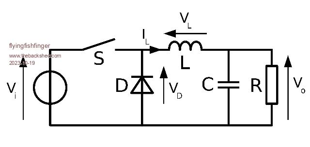 Boost: 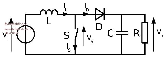 So the arrangement of the inductor vs the MOSFETS is different as is the control algorithm as already indicated.. R |
||||
| nickskethisniks Guru Joined: 17/10/2017 Location: BelgiumPosts: 458 |
The software should work with some minor changes, no problem. Buck or boost will work the same, increase dutycycle for more energy flow until mppt is reached. The hardware, yes a little bit different, but not much, I have a simple protoboard that works with simple voltage tracking firmware, but I still need to add 2 current sensors to work with Peter his code. My code has stability issues when running the loop too fast, 1ms works ok. |
||||
| mab1 Senior Member Joined: 10/02/2015 Location: United KingdomPosts: 209 |
I'm not sure what your definition of higher voltage is; mine runs at a about 5:1 voltage ratio on a 24v system. https://www.thebackshed.com/forum/ViewTopic_mobile.php?FID=4&TID=15938 For the mosfets i used one that was recommended by pd-- : irf200p222 - 200V - not cheap and i suspect I'm massively underrunning them as they are rated to 182A continuous. The schottkys are apt30s20bctg, 200V again. As for boost - I'm probably speaking beyond my knowledge here, but i think you have to determine the maximun allowable pwm duty cycle % (obviously you can't run 100%), which would probably depend on in:out voltage ratio, and you might have to monitor input amps during a mppt scan, but it ought be doable. Edited 2023-10-20 01:48 by mab1 |
||||
| poida Guru Joined: 02/02/2017 Location: AustraliaPosts: 1418 |
How the code works: It requires one simple fact to be true, that is output voltage is proportional to duty cycle width. And that it is monotonic such that it is always proportional to PWM width from zero to max width. Once that is sorted, and it IS since it's a buck converter the code periodically does a search from the smallest PWM width to the max width IF NEEDED, looking for the maximum output power that is going into the battery. (I frankly could not give a rat's what the solar array power is doing all I want is to get max power INTO the battery. max power OUT OF the array is of zero interest. we are charging a battery here..) The PWM width that give max. power into the battery is noted and the scan has completed. For the remainder of the 60 seconds a slow closed loop control ("tracking") is run, keeping output at this PWM width but also limiting output current if needed due to battery voltage arriving at the absorb or float settings or the user's max. current being exceeded. To control the output all I need do is reduce or increase the PWM width. The scan can be stopped early should there be an excess of power available and the battery voltage is exceeded or the max output current setting is exceeded. Either of these will set the PWM run max value for the remainder of the 60 seconds. Boost converters also have the same monotonic proportional relation of output voltage verses PWM width. I think my code will run fine, apart from some minor changes to stop condition testing. It now tests if battery voltage is greater than array voltage and stops the converter. Obviously this would be useless in a boost design. But the mppt scan code will not need any change. Nor the tracking code (which runs for about 57 seconds after the mppt scan) Just some of the run time test conditions. wronger than a phone book full of wrong phone numbers |
||||
| flyingfishfinger Senior Member Joined: 12/09/2020 Location: United StatesPosts: 110 |
So I just came back from visiting our offgrid site after 4 months absence. The controller is running fine, but I do need some help with the software due to some pretty strange behaviour. I mentioned before that the "night" current is sometimes negative, near zero due to slight sensor drift. I also mentioned I didn't have any luck clamping it to zero myself. There also is not much light during the winter months (coming up), so I guess it spends quite a bit of time in night mode these days. As a result, I had accumulated NEGATIVE 72 kWh of charge and the current sensors were reporting NEGATIVE 1A in night mode (??). I obviously recalibrated the device when I was there, but this is kind of a majorly annoying bug. The temperature at my site fluctuates from +40C in high summer to just under freezing in the winter but not that much during the day. From the datasheet of the ACS758LCB-050U, the error is about 10mV from 0C to 25C and the sensitivity is 60mV / A. So I might get 0.2A drift over temperature (about what I do see). At 100V input, that's a 20W difference and over 120 days, if my math is right, that is approximately 56kWh of error, not too far from what I saw (!). If my batteries spend most of their time in float when I'm not there, I would be mostly accumulating error instead of real charge. Do we have some thoughts about improving / fixing the behaviour? Edited 2023-11-17 08:04 by flyingfishfinger |
||||
| poida Guru Joined: 02/02/2017 Location: AustraliaPosts: 1418 |
I suspect the mppt is not draining energy from the battery in this situation. so there is that. But I agree this behavior is disappointing. Thanks for working out a potential cause for it. The current sensors have large offsets and offset tempco as you have shown. These error sources will be present during the daytime as well as at night. So they will effect both NIGHT mode and the daytime MPPT and ABSORB modes. maybe you and I could work out some sort of plan to deal with the offset errors. (sensor gain seems to be stable, thankfully) my first idea: whenever a sensor reports negative current, this will trigger a recalibration of the zero point. Maybe only do this once an hour. We do this in all operating modes. what could go wrong with this? there could be more time spent in MPPT but under very low power. this is not a problem. probably a good thing. During daytime with proper solar power, the recal will not run since current values will be positive and a lot higher than the offset drift. how I would code it: monitor both current sensors, checking once a minute. if after 60 minutes of a sensor having a negative value, the recal code will be run and the 60 minute timer is reset to zero. It will be important that we prove that there is zero current flowing through the sensors at these times we recalibrate. what do you think FF? wronger than a phone book full of wrong phone numbers |
||||
| flyingfishfinger Senior Member Joined: 12/09/2020 Location: United StatesPosts: 110 |
so there is that. Your suggestion seems reasonable. What do you mean by "could spend more time in MPPT under low power" ? The trigger for night mode is still some small number of positive W - except that if the current is negative, that will be negative as well. I am planning to head back up on Dec 1 - 3rd, and after that probably not until spring. Do you think we can work something out before then that I can try out? No big deal if not, as long as having a negative current will still charge the battery (does the MPPT scanning check for "least negative" in addition to "most positive" power correctly?) I'm using the I2C version, if that changes anything (on that note, I've run it up to about 1500W and found no I2C / display issues) R |
||||
| poida Guru Joined: 02/02/2017 Location: AustraliaPosts: 1418 |
important that I know you are using the i2c version - I don't want to work on the wrong one for you. the mppt search looks for the greatest output power, when scanning the PWM width range from very low to max width. This search is only done when in MPPT mode or NIGHT mode The search records the max output power and once found will set the tracking code to only go up to the PWM that produced that max power. I will try to do this over the weekend and test it. wronger than a phone book full of wrong phone numbers |
||||