|

|
Forum Index : Electronics : 150V 45A MPPT - roll your own
| Author | Message | ||||
| flyingfishfinger Senior Member Joined: 12/09/2020 Location: United StatesPosts: 110 |
Ooh that looks like a nice part - sadly it's out of stock everywhere. This looks like an acceptable substitute, APT30S20BCTG Will order up a couple and see what happens! |
||||
| soudirector Newbie Joined: 14/05/2023 Location: NigeriaPosts: 26 |
I prefer using IRFP260N Mosfet 200v, 50A, DS(on) = 0.04Ω how times flies  |
||||
| Ziki_the Newbie Joined: 13/04/2023 Location: YugoslaviaPosts: 39 |
Question? For current sensor is it posible to use lem ltsp 25-np? This is current output hall, not voltage out. I have few of them. Thanks Pozdrav iz Srbije |
||||
| poida Guru Joined: 02/02/2017 Location: AustraliaPosts: 1418 |
I think you can use these but you might have to mount it in a way that permits you to fit a resistor across M and ref the pcb is designed for the 3 pin voltage output type so it's not ready for the 4 pin current output version. One of my mppt has the LEM sensors mounted upside down, with the pins pointing UP and I have 3 wires leading from pins to the pcb. It's not pretty but it works fine. wronger than a phone book full of wrong phone numbers |
||||
| Ziki_the Newbie Joined: 13/04/2023 Location: YugoslaviaPosts: 39 |
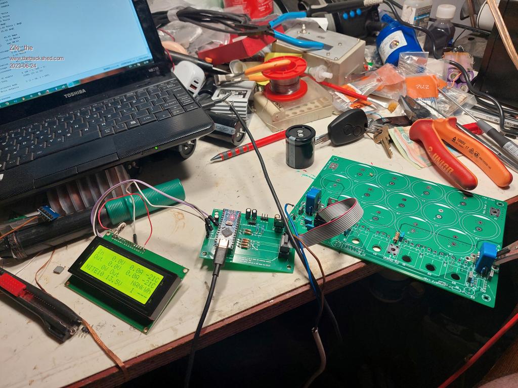
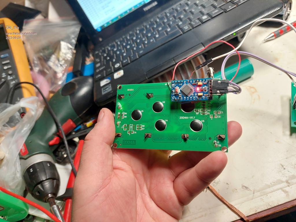
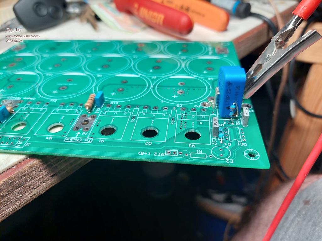
So i have done a little work on one board.   Pro mini clone is used for display board.  For current sensors, do i need to put one more wire in the midle hole? Just this work for now.  Pozdrav iz Srbije |
||||
| flyingfishfinger Senior Member Joined: 12/09/2020 Location: United StatesPosts: 110 |
Ok, I rebuilt the blown parts. Turns out the exploded diodes took 2 out of my 3 FETs with them... now it's back to working. But I have a question about calibration. When I put the firmware in "cal" mode, the display freezes. Is that the intended behaviour (to lock it at the exact current that is being used at that moment) or is there something I'm not doing correctly? R Edited 2023-07-12 06:32 by flyingfishfinger |
||||
| poida Guru Joined: 02/02/2017 Location: AustraliaPosts: 1418 |
putting it in cal mode is not mandatory. it was more of a test for me to see if there is much change in the calibration of the 4 values when running or not. The display must freeze when in cal mode since it disables the 20kHz interrupt which contains code that sends out data to the LCD. I should have made this clear to people that cal mode is not much use and does not need to be used. Sorry if it caused any issues. wronger than a phone book full of wrong phone numbers |
||||
| flyingfishfinger Senior Member Joined: 12/09/2020 Location: United StatesPosts: 110 |
No problem, just wondering how best to calibrate the thing. Any suggestions? All I've got is a shunt ammeter (actually just current setting on DMM) that will go to 10A, heh. R |
||||
| poida Guru Joined: 02/02/2017 Location: AustraliaPosts: 1418 |
Zikki, I think you have it connected up OK. The 5V and Ground are lined up and soldered in, the "O" and "Ref" need a resistor. If it works then no need to do anything else. (for those who might be wondering) the 4 pin LEM sensor schematic is and the 3 pin sensor is Edited 2023-07-12 08:26 by poida wronger than a phone book full of wrong phone numbers |
||||
| flyingfishfinger Senior Member Joined: 12/09/2020 Location: United StatesPosts: 110 |
Progress report: Fixed up my unit and it runs at 1000W with no issues so far - the higher input voltage (130V) is also handled nicely with the new diodes. Question: I'm still having the issue where the current sensor reports incorrect values when there's no charging (anywhere between 0.1 and 0.6A instead of zero) despite zeroing the current beforehand. My theory is that running it at high currents breaks the calibration after some time due to temperature or something. I wonder if an improvement would be to call the "zero" function each time the device is in night mode? That way it should in theory fix itself after each day. I'll try this next time I go up to my site but that won't be for about 2 months. Cheers, R |
||||
| poida Guru Joined: 02/02/2017 Location: AustraliaPosts: 1418 |
the current sensors to take a "set", in other words their zero current output value can represent + or - a bit of current. OR zero current will produce an output with a bit + or - from zero position. I have found this hysteresis is stable, so long as you do not change direction of current. In the mppt design, current direction does not change. This permits us to let the hysteresis to accumulate and we keep calibrating the zero point and gain. Things tend to settle down after a couple of good power use periods and recalibrations. Also, calibrating at 10A is fine. No need to get it perfect, we just need reasonable values for the mppt program to work. wronger than a phone book full of wrong phone numbers |
||||
| poida Guru Joined: 02/02/2017 Location: AustraliaPosts: 1418 |
I could make a version of the code to measure both current sensors after a few hours of "NIGHT" and then store that as their new zero current settings. You like that? I need to be at work to do this, I have a lot of spare time when I am at work. (lucky, eh?) wronger than a phone book full of wrong phone numbers |
||||
| flyingfishfinger Senior Member Joined: 12/09/2020 Location: United StatesPosts: 110 |
Oh, I figure it won't be hard to add myself - but if you're offering I won't say no :) Do keep in mind I use the I2C version! My main issue is that since I'm away most of the time and use no power, the batteries spend their time in absorb / float with maybe a bit of bulk in the morning. Thus generally small amounts of current are measured, which increases the error on the total capacity charged significantly more than when higher currents are being used. Also, I think I mentioned the negative current readings at night causing the accumulated capacity to DECREASE by morning, maybe the zeroing would help with that as well. Maybe we zero once an hour at night? Probably overkill but might be more accurate no? R Edited 2023-07-27 05:45 by flyingfishfinger |
||||
| soudirector Newbie Joined: 14/05/2023 Location: NigeriaPosts: 26 |
I tired to program my nano using the code with I2C. i got error exit status 1 Compilation error: no matching function for call to 'LiquidCrystal_I2C::LiquidCrystal_I2C(int)' Why the I2C file is present in the folder with the ino file. What could be the problem? how times flies  |
||||
| soudirector Newbie Joined: 14/05/2023 Location: NigeriaPosts: 26 |
this was highlighted when the error occurred LiquidCrystal_I2C lcd(0x27); // set the LCD address to 0x27 for a 16 chars and 2 line display how times flies  |
||||
| pd-- Senior Member Joined: 11/12/2020 Location: AustraliaPosts: 122 |
Do you have " #include <LiquidCrystal_I2C.h> " at the start of your code. There are multiple LiquidCrystal_I2C libraries you may be using the wrong one i haven't tried it but give this one a go https://www.arduino.cc/reference/en/libraries/liquidcrystal-i2c/ |
||||
| soudirector Newbie Joined: 14/05/2023 Location: NigeriaPosts: 26 |
Yes, i do have that. But i have fix the problem. Thanks how times flies  |
||||
| soudirector Newbie Joined: 14/05/2023 Location: NigeriaPosts: 26 |
I was wondering if this can work without issues. how times flies  |
||||
| Ziki_the Newbie Joined: 13/04/2023 Location: YugoslaviaPosts: 39 |
Look like ATX choke. Maybe 5pcs stocked and some thing like 15-17turns with multply coper wire, litz.. My sugestion.. Pozdrav iz Srbije |
||||
| soudirector Newbie Joined: 14/05/2023 Location: NigeriaPosts: 26 |
this inductor is for mppt not ATX choke how times flies  |
||||